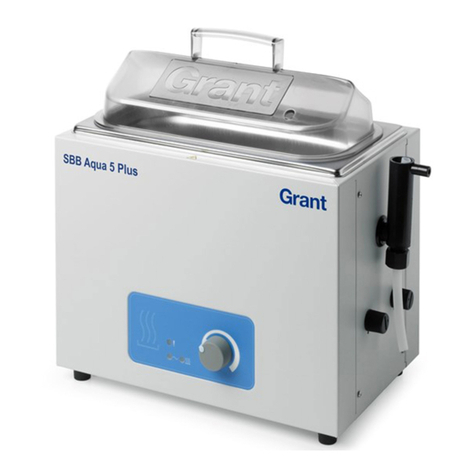
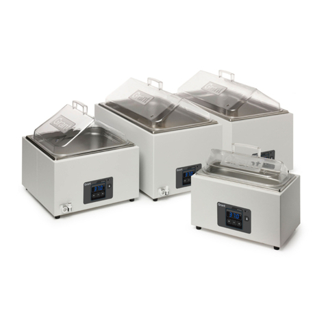
Grant SAP Series User manual

Unstirred water bath
SAP, JBA & JBN
Service Manual

Unstirred water bath SAP, JBA, JBN Service Manual (Version 2.0) July 2014
31667 Page 2 of 23
Contents
1Introduction ........................................................................................................................3
1.1 Service Address...........................................................................................................3
1.2 Servicing Advice.........................................................................................................3
1.3 Cautions & Warnings..................................................................................................3
1.4 Electrical Safety ..........................................................................................................3
2Product Description............................................................................................................4
2.1 SAP, JBA & JBN range ..............................................................................................4
2.2 Basic Description ........................................................................................................4
2.3 Dismantling a unit.......................................................................................................6
2.3.1 Removing the base plate......................................................................................7
2.3.2 Removing the tank, heater and probe assembly...................................................8
2.3.3 Removing the PCB assembly ............................................................................10
2.3.4 Removing the front panel membrane keypad....................................................10
2.4 Reassembling the unit ...............................................................................................10
2.5 System Schematic & Interconnect Diagram .............................................................11
3Common service tasks......................................................................................................12
3.1 Resetting the Over Temperature Cut-out..................................................................12
3.2 Replacing a tank, heater and probe assembly ...........................................................12
3.3 Replacing the fuses....................................................................................................13
3.4 Replacing Control and Display PCB.........................................................................13
4Fault Diagnostics and Test ...............................................................................................14
4.1 Test Equipment & Tools Required ...........................................................................14
4.2 Testing and Fault finding ..........................................................................................14
4.2.1 Test/fault-finding flowchart...............................................................................15
4.2.2 Useful values for fault finding...........................................................................17
4.3 Final Tests –Electrical Safety...................................................................................17
4.3.1 Check Earth Connection....................................................................................17
4.3.2 Check Insulation ................................................................................................17
4.4 List of display messages............................................................................................18
4.4.1 Operating Messages...........................................................................................18
4.4.2 Fault/Diagnostic Messages ................................................................................18
5Service Parts .....................................................................................................................19
6Other Technical Documentation.......................................................................................22
Unstirred water bath SAP, JBA, JBN Service Manual (Version 2.0) July 2014
31667 Page 3 of 23
1 Introduction
1.1 Service Address
If further help or assistance is required please contact Grant Instruments by one of the
methods below:
Service Department
Grant Instruments (Cambridge) Ltd
Shepreth
Cambridgeshire
SG8 6GB
England
Tel: +44 (0) 1763 260 811
Fax: +44 (0) 1763 262 410
1.2 Servicing Advice
Adjustment, maintenance and repair of the unit described in this service manual should only
be carried out by qualified people who are aware of the workshop practices appropriate to the
grade of servicing.
In particular, the unit cover should only be removed by people who have been trained, to
avoid the risk of electric shocks.
1.3 Cautions & Warnings
Caution and warning statements are given in the form shown:
CAUTION: Used to indicate a correct method or procedure to be followed to avoid damage
to equipment and other property.
WARNING: Used to call attention to the use of materials, processes, methods, tools,
procedures or limits that must be followed exactly to avoid personal injury.
1.4 Electrical Safety
The water bath meets the requirements of IEC 61010.
Before any connection is made to an AC power supply, ensure that the socket outlet to be
used is provided with an effective earth/ground connection and matches the voltage and
frequency rating of the bath
WARNING: Any interruption of the earth/ground conductor or earth/ground connections
within or outside the unit may render the unit dangerous to use.
It is recommended that the power supply is fitted with a residual earth leakage current trip.

Unstirred water bath SAP, JBA, JBN Service Manual (Version 2.0) July 2014
31667 Page 4 of 23
2 Product Description
2.1 SAP, JBA & JBN range
The ,SAP, JBA and JBN ranges of unstirred water baths are available in 8 tank sizes and in 2
mains voltage types.
The following table defines the models and serial numbers covered by this service manual.
Product Code1
Voltage
Applicable Serial Nos (Date)2
JBA#
220-230V
U*1332001 onwards (9th Aug 2013)
JBA# AUS
220-230V
V*1332001 onwards (9th Aug 2013)
JBA# US
110-120V
V*1427001 onwards (7th July 2014)
JBN#
220-230V
U*1332001 onwards (9th Aug 2013)
JBN#AUS
220-230V
V*1332001 onwards (9th Aug 2013)
JBN# US
110-120V
U*1336001 onwards (5th Sept 2013)
SAP#
220-230V
U*1332001 onwards (9th Aug 2013)
SAP# AUS
220-230V
V*1336001 onwards (5th Sept 2013)
SAP# US
110-120V
U*1336001 onwards (5th Sept 2013)
1. Where # denotes the bath size e.g. 5, 2S, 26 or D (dual bath 5&12)
2. Where * denotes an alphanumeric character dependent on bath type and size
2.2 Basic Description
All of the water baths follow the same construction method. A single piece painted case
contains mains inlet and wiring and the Control & Display PCB assembly. The tank, heater
and probe assembly is fitted into the case from the top and held in place by a number of small
bent tabs on the case which provide an interference grip. Heat resistant ties are used as a
secondary method to hold the tank to the case. A base plate with integral feet is attached to
the case bottom using M3 screws.
Major component parts are
Control & Display PCB assembly
Tank, heater and probe assembly
Mains inlet and wiring
Chassis assembly
Water in the bath is heated using a silicone mat heater that is glued to the underside of the
stainless steel tank. The heater mat includes one or more manual reset fixed over-
temperature cut-outs for safety that are bonded to the heater mat. The over-temperature cut-
out is wired to the heater using individual insulated wires. The control temperature probe is
mounted to the side of the tank and covered with an insulating patch. Power to the heater mat
is controlled by the Control & Display PCB assembly which is mounted to the case. The
control TRIAC protrudes from the Control & Display PCB assembly and is mounted to the

Unstirred water bath SAP, JBA, JBN Service Manual (Version 2.0) July 2014
31667 Page 5 of 23
case for heat-sinking. The front panel keypad provides the user interface with 4 buttons (JBA
& JBN) or 7 buttons (SAP).
The unit contains microprocessor control firmware which is factory fitted. The firmware
version is shown on the front panel display for 2 seconds when the unit is switched on.
Firmware is only factory upgradable. If an upgrade is required then the unit can be returned
to Grant Instruments or the Control PCB assembly replaced with one containing the upgraded
firmware.
In the event of a failure, component assemblies can be replaced by Grant Instruments or
authorised service centres and distributors.
Use the Fault Diagnostic and test guide, common repair tasks section and dismantling guide
to undertake an effective repair.

Unstirred water bath SAP, JBA, JBN Service Manual (Version 2.0) July 2014
31667 Page 6 of 23
2.3 Dismantling a unit
The dismantling guide describes a SAP 12 litre unit. All other bath sizes use the same
assembly format with the following differences:
JBA units are not fitted with a bath drain and tap
The 34 litre 110-120V model has a fixed mains cord
The 34 litre bath tank is held in by 4off M4 studs and nuts
JB and SAP baths have different membrane keypads
There are 2 control and display PCB hardware variants . One for small bath sizes and one for
large baths
WARNING: Do not dismantle the unit unless you have the equipment and necessary skills to
verify that it is safe after re-assembly –see section 4.3
WARNING: Disconnect the unit from the mains voltage supply by unplugging the mains
cord before dismantling the unit
Tools required
1 x Pozidrive screwdriver No.1
1 pair flush cutting side cutters
1 x fine nosed pliers or similar
M4 nut spinner with flexible shaft (approx 300mm long shaft
required)
Control and display PCB assembly
Drain assembly
Mains inlet
Probe
Tank, heater and probe assembly
Over-
temperature
cut-out
Location of internal component parts

Unstirred water bath SAP, JBA, JBN Service Manual (Version 2.0) July 2014
31667 Page 7 of 23
2.3.1 Removing the base plate
Remove the 4 Posidrive screws holding the base plate in position. The plate can then be lifted
off the case. All the internal component parts are now visible
On later manufactured units, the base plate is also secured with plastic push fit rivets.
Remove these by lifting the head of the rivet with flush cutting side cutters
1
2
3
4

Unstirred water bath SAP, JBA, JBN Service Manual (Version 2.0) July 2014
31667 Page 8 of 23
2.3.2 Removing the tank, heater and probe assembly
Following on from the instructions above:
Cut and remove the 2 off tank retaining heat resistant ties using the cutters
Disconnect the earth cable from the tank
Disconnect the mat power leads from the PCB assembly
Disconnect the probe lead from the PCB assembly
.
WARNING: Do not disconnect by pulling on the wires –pulling on the wires could expose
live conductors or lead to the wire coming off in use and causing a hazard. The crimp
receptacles must be eased off the spade tabs using fine nosed pliers or similar on the crimp
body.
Heat resistant tie #1
Heat resistant tie #2
Tank earth cable
Probe lead
Mat power leads

Unstirred water bath SAP, JBA, JBN Service Manual (Version 2.0) July 2014
31667 Page 9 of 23
Remove the drain tube from the tank by sliding it off the plastic fitting.
Holding the tank against the bench, lift the outer case up and away from the tank and heater
assembly
The PCB and mains cable and inlet are now accessible.

Unstirred water bath SAP, JBA, JBN Service Manual (Version 2.0) July 2014
31667 Page 10 of 23
2.3.3 Removing the PCB assembly
Following on from the instructions above
Disconnect the mains cables (brown, blue and green/yellow) from the PCB
Disconnect the key pad connector from the back of the PCB
On 2,5 and 12 litre and Dual baths lift out the 3off plastic rivets at the front of the PCB flush
cutting side cutters. On 18, 26 and 34 litre baths lift out the 2 plastic rivets at the front of the
PCB and unscew the M3 screw holding the TRIAC in place.
Gently lift the PCB to release it from the locating fixings at the back of the PCB
2.3.4 Removing the front panel membrane keypad
Following on from the instructions above:
The membrane is fixed to the outer bath case by adhesive. Use the fine blade to lift the
corner of the membrane then gently peel from the front of the bath case. Once removed
membrane keypad cannot be re-used and must be replaced with a new part.
2.4 Reassembling the unit
Follow the instructions above in reverse using the existing components or, if faulty, replaced
with new components. Ensure the following :
The tank is fitted the correct way around.
The TRIAC component is correctly seated flat on the chassis with heat-sink paste and secured
with a plastic rivet or M3 srew for larger baths.
Correct new heat resistant ties are used to secure the tank. These are available from Grant
Instruments. Part no. 31308 –All bath sizes except 18 litre. Part no.31309 –18 litre
WARNING: The unit must be tested and inspected to verify that it is electrically safe after
re-assembly –see section 4.3
Mains cables
Keypad connector
Plastic rivets
TRIAC

Unstirred water bath SAP, JBA, JBN Service Manual (Version 1.0) September 2013
31667 Page 11 of 23
2.5 System Schematic & Interconnect Diagram
Blue
White (230V), Black (120V)
Yellow/Green
Blue
Yellow/Green
Brown
J2
J3
J6
J9
J5 –Neutral
J8 –Earth
J7 –Live
U16 - SMPSU
Membrane Keypad
4 buttons (JBA, JBN)
7 buttons (SAP)
Mains
Power
Inlet
Heater Mat
Temperature Probe
Reprogramming Edge
Connector
To Case
Fuses
Over-
temperature
cut-out
TRIAC
LED Display
(on reverse side)
Control and display PCB
Tank, heater and probe assembly
Duplicate configuration:
Control and display PCB
Membrane Keypad
Tank , heater and probe assembly
SAPD only
Note:
Mains connections are shown for PCB issue B.
PCB issue C and above are ordered:
Earth, Neutral, Live (PCB designators are unchanged)

Unstirred water bath SAP, JBA, JBN Service Manual (Version 1.0) September 2013
31667 Page 12 of 23
3 Common service tasks
3.1 Resetting the Over-temperature Cut-out
This task is required when the unit displays an diagnostic message.
WARNING: Disconnect the unit from the mains voltage supply by unplugging the mains
cord before dismantling the unit
Remove the base plate of the bath - See section 2.3.1
Inspect the mat for any sign of blistering, discolouring or other damage due to excessive
temperatures –if the mat is damaged it must be replaced.
If the mat is undamaged, locate the cut-out device fitted to the heater mat. See photo below.
Note, the 34 litre bath has 3 separate cut-out devices.
Depress the actuator in the centre of the device. There will be an audible click as this is
relocated.
If there is no click, then the cut-out has not activated. Inspect the heater mat and wiring for
faults.
Refit the base plate.
Refill the bath and connect the mains lead.
Switch on the bath and check the water temperature is displayed as expected.
If the display continues to show OTC then there is a fault in the heater circuit. Check the
electrical continuity of the heater mat. Typical resistance values are given in Section 4.2.2.
Over-temperature cut-out device
3.2 Replacing a tank, heater and probe assembly
This is required if the tank is damaged or the mat or probe are faulty
WARNING: Disconnect the unit from the mains voltage supply by unplugging the mains
cord before dismantling the unit
Dismantle the unit following instructions in Section 2.3 as far as removing the tank
Remove the drain fittings from the tank
Refit the drain fittings to the new tank ensuring that the O-ring is correctly seated
Fit a replacement tank, heater and probe assembly and re-assemble following the instructions
in section 4.2

Unstirred water bath SAP, JBA, JBN Service Manual (Version 1.0) September 2013
31667 Page 13 of 23
3.3 Replacing the fuses
The fuses are located on the control and display PCB assembly. To test and replace them,
follow the dismantling instructions in section 2.3 as far as removing the tank. The fuses are
then accessible.
CAUTION: Only replace the fuses if the fault has been fully diagnosed and the fault has
been rectified
WARNING: The fuses must only be replaced by the correct type and rating, see below.
Product safety certification cannot be assumed to be valid if approved fuse type is not fitted.
Model
110-120V units
& 220-230V units
Fuse type and rating
Approved fuse type
JBA5, JBA12,
JBN5, JBN12,
SAP2, SAP2S, SAP5, SAP12
SAPD
F10AH250V
5 x 20mm, 10A quick blow,
ceramic, 1500A interrupt
rating at 250Vac.
Littelfuse 0216010P
JBA18,
JBN18, JBN26,
SAP18, SAP26, SAP34
F12.5AH250V
5 x 20mm, 12.5A quick
blow, ceramic, 1500A
interrupt rating at 250Vac.
Littelfuse 021612.5P
CAUTION: When replacing the fuses take care to avoid distorting the clips. If they do not
grip the fuse tightly there is a risk of overheating and nuisance fuse failures
3.4 Replacing Control and Display PCB
Follow the dismantling instructions in section 2.3 as far as removing the PCB assembly
Fit a correctly configured replacement PCB and reassemble and test the unit following the
instructions in section 4.3

Unstirred water bath SAP, JBA, JBN Service Manual (Version 1.0) September 2013
31667 Page 14 of 23
4 Fault Diagnostics and Test
4.1 Test Equipment & Tools Required
The following additional tools are required:
Digital multi-meter
High voltage tester
4.2 Testing and Fault finding
The flow diagrams in 4.2.1 can be used to diagnose faults and should be used to verify proper
functioning after a repair has been carried out.
Additional information about messages and fault codes can be found in 4.4
Once functioning correctly the unit is designed to operate to its factory specification without
further adjustment.
However, if any component assemblies are replaced it is recommended that any user
temperature preset, alarm and user calibration settings are reconfigured

Unstirred water bath SAP, JBA, JBN Service Manual (Version 1.0) September 2013
31667 Page 15 of 23
4.2.1 Test/fault-finding flowchart
Part 1 –Start-up checks
SWITCH ON
Check and replace
fuses and restart
Reports Correct
Model
YES
NO
NO
Replace Control PCB
with correct firmware
and configuration
Did this fix the
fault?
NO
Report Firmware
version, Model, Bath size
Reports Correct
Bath Size?
Display water temperature
Temperature
Displayed? Reports “OtC”
Over-temperature trip
on heater mat has been
activated. Switch off
bath and allow to cool.
Reset over temperature
trip (see 3.1)
Temperature
displayed?
Consult Grant
Instruments
NO
YES
Bath started correctly
YES
STOP
NO
YES
Temperature
displayed?
YES
NO Reports “dry”
Reports “Prb”
YES
Reports “dog” Replace Control PCB
Check control probe connection and resistance. Replace probe.
Check/replace sequence, most likely to least likely:
Check bath is filled with suitable amount of water. Fill with water
and restart
Display reports:
YES
NO
NO
Reports Version 1.02
or above NO
Is Display Working
YES
YES

Unstirred water bath SAP, JBA, JBN Service Manual (Version 1.0) September 2013
31667 Page 16 of 23
Part 2 –Operation checks
START
Refer to Grant Instruments Service Department for
advice
Fill bath with water above the minimum fill
level
Bath
starts to heat
water?
STOP
NO
YES
NO
Unit reports a fault?
Follow check/replace sequence on flowchart 1 from
“Temperature displayed?” box
YES
NO
Switch bath on and wait until temperature is
displayed.
Press ‘set’ button
Display
shows ‘oC’?NO
Press ‘set’ button and change the set
temperature to 5C above the water
temperature
YES
Display temperature increases. Heater
indicator illuminates (SUB AQUA PRO)
Display rolling bar appears to indicate
heating (JB AQUA, JB NOVA)
Wait for bath to stabilise at set
temperature
YES
Bath
controls water at set
temperature?
Change set temperature
to 10° C and allow to cool
Replace Control PCB
Check control probe mounting, connection and resistance. Replace probe if
required.
Check/replace sequence, most likely to least likely:
Check bath is filled to minimum water level.
If required fill with more water and wait for temperature to stabilise again
Follow check/replace sequence on flowchart 1 from
“Temperature displayed?” box
Fit Lid if required (above 60°C)
Replace Membrane
Does keypad buttons
function correctly
NO
YES

Unstirred water bath SAP, JBA, JBN Service Manual (Version 1.0) September 2013
31667 Page 17 of 23
4.2.2 Useful values for fault finding
Component
Measured Value
Heater 2 litre models
68-80Ω (120V)
252-294Ω (230V)
Heater 2 litre shallow & 5 litre models
39-45Ω (120V)
144-168Ω (230V)
Heater 12 litre models
17-20Ω (120V)
63-74Ω (230V)
Heater 18 litre & 26 litre models
13-15Ω (120V)
36-42Ω (230V)
Heater 34 litre models
10.5-12.5Ω (120V)
28-32Ω (230V)
Heater dual litre models
See 5 litre and 12 litre values above
Probe
approx 1070 to 1120Ω at room temperature
(18-31°C)
4.3 Final Tests –Electrical Safety
After any repair, the unit should be electrically tested to ensure that it is safe.
WARNING: The following process should always be carried out after any repair to ensure
safety. If the bath fails either test below then it must be repaired and successfully retested
before being put back into operation.
4.3.1 Check Earth Connection
Using an Ohm meter or, preferably, a specialised earth bond checker (max 25A test current),
verify that the resistance between the earth pin of the equipment inlet and the exposed
metalwork is less than 0.1Ohm. In the case of the painted panels it is acceptable to make the
contact with the screw heads.
4.3.2 Check Insulation
Use a high voltage tester set to 2000VDC. Connect the live and neutral terminals of the bath
together and apply the test voltage between them and the earth contact of the bath. The test
voltage should be raised to its full value in less than 2 seconds, held for 2 seconds and then
reduced back to zero.
No breakdown or repeated flashover shall occur. Corona effects and similar phenomena are
disregarded
4.3.3 Routine testing
If routine tests are to be made, we recommend a test of the integrity of the protective
earth conductor and an insulation test at 500V DC. Routine flash tests are not
recommended for any electrical equipment, because repeated high voltage tests degrade
insulation materials.

Unstirred water bath SAP, JBA, JBN Service Manual (Version 1.0) September 2013
31667 Page 18 of 23
4.4 List of display messages
4.4.1 Operating Messages
,,,,, - Unit model type
–countdown timer menu item
–countdown timer has ended
,, –Preset temperature menu item
–dry protection alarm menu item
–an alarm temperature has been reached
, –timer or alarm is off or on
,, –Low point, High point and Single point calibration menu item
–User calibration value has been accepted
–keyboard has been locked
–Keyboard has been unlocked
4.4.2 Fault/Diagnostic Messages
–unit has been started with no liquid or boiled dry
–Bath heater mat has overheated. Over-temperature cut-out has activated
–temperature measuring probe is measuring a value out of range
–Internal circuit watchdog has activated
–Unit is in factory configuration mode

Unstirred water bath SAP, JBA, JBN Service Manual (Version 1.0) September 2013
31667 Page 19 of 23
5 Service Parts
Bath
Part description
Part no. (220-230V)
Part no. (110-120V)
SAP2
Case & Base Plate Assembly 2L
31334
31334
PCB
31285
31285
Heater Mat*
31269
31274
Tank 2L*
31253
31253
Temp Probe*
14014
14014
Inlet & Wire Assembly
31327
31327
Membrane
31302
31302
SAP2S
Case & Base Plate Assembly 2LS
31335
31335
PCB
31285
31285
Heater Mat*
31270
31275
Tank 2LS*
31254
31254
Temp Probe*
14014
14014
Inlet & Wire Assembly
31327
31327
Membrane
31302
31302
SAP5
Case & Base Plate Assembly 5L
31336
31336
PCB
31285
31285
Heater Mat*
31270
31275
Tank 5L*
31256
31256
Temp Probe*
14014
14014
Inlet & Wire Assembly
31327
31327
Membrane
31302
31302
SAP12
Case & Base Plate Assembly 12L
31337
31337
PCB
31285
31285
Heater Mat*
31271
31276
Tank 12L*
31257
31257
Temp Probe*
14014
14014
Inlet & Wire Assembly
31328
31328
Membrane
31302
31302
Drain Panel Mount
31251
31251
Drain Fitting
31315
31315
Drain Insert
31252
31252
SAP18
Case & Base Plate Assembly 18L
31339
31339
PCB
31286
31286
Heater Mat*
31272
31277
Tank 18L*
31258
31258
Temp Probe*
14014
14014
Inlet & Wire Assembly
31329
31329
Membrane
31302
31302
Drain Panel Mount
31251
31251
Drain Fitting
31315
31315
Drain Insert
31252
31252

Unstirred water bath SAP, JBA, JBN Service Manual (Version 1.0) September 2013
31667 Page 20 of 23
Bath
Part description
Part no. (220-230V)
Part no. (110-120V)
SAP26
Case & Base Plate Assembly 26L
31339
31339
PCB
31286
31286
Heater Mat*
31272
31277
Tank 26L*
31259
31259
Temp Probe*
14014
14014
Inlet & Wire Assembly
31329
31329
Membrane
31302
31302
Drain Panel Mount
31251
31251
Drain Fitting
31315
31315
Drain Insert
31252
31252
SAP34
Case & Base Plate Assembly 34L
31340
31340
PCB
31286
31286
Heater Mat*
31273
31278
Tank 34L*
31260
31260
Temp Probe*
14014
14014
Inlet & Wire Assembly
31327
31327
Membrane
31302
31302
Drain Panel Mount
31251
31251
Drain Fitting
31315
31315
Drain Insert
31252
31252
SAPD
Dual Case & Base Assembly
31341
31341
PCB
31285
31285
Heater Mat 5L*
31270
31275
Heater Mat 12L*
31271
31276
Tank 5L*
31256
31256
Tank 12L*
31257
31257
Temp Probe*
14014
14014
Inlet & Wire Assembly
31331
31331
Membrane
31302
31302
Drain Panel Mount
31251
31251
Drain Fitting
31315
31315
Drain Insert
31252
31252
* Spare Part Descriptions with an asterix (*) indicate that parts should be purchased together
and will be supplied pre assembled
Model type and size need to be defined when ordering PCB
This manual suits for next models
17
Table of contents
Other Grant Laboratory Equipment manuals

Grant
Grant JB Academy Series User manual

Grant
Grant R Series User manual

Grant
Grant SUB Aqua Plus User manual

Grant
Grant QBA Series User manual

Grant
Grant Optima T100 User manual

Grant
Grant CRFT User manual

Grant
Grant UVT-B-AR User manual

Grant
Grant XUBA Series User manual

Grant
Grant GLS Aqua Plus User manual

Grant
Grant SUB User manual
Popular Laboratory Equipment manuals by other brands

SPEX SamplePrep
SPEX SamplePrep 6875D quick start guide

Miele professional
Miele professional PG 8596 operating instructions

Labnet
Labnet MPS 1001 Mini Plate Spinner instruction manual

seward
seward Stomacher 80 Biomaster user manual

vacuubrand
vacuubrand VHC pro Instructions for use

Sanuvox
Sanuvox Bio-Wall MAX instruction manual