Spartan Mini Cam Setup guide

S p a r t a n M i n i C a m
V i d e o I n s p e c t i o n S y s t e m
Owners Instruction Manual
( 8 0 0 ) 4 3 5 - 3 8 6 6
SPARTAN TOOL L.L.C.

Page2
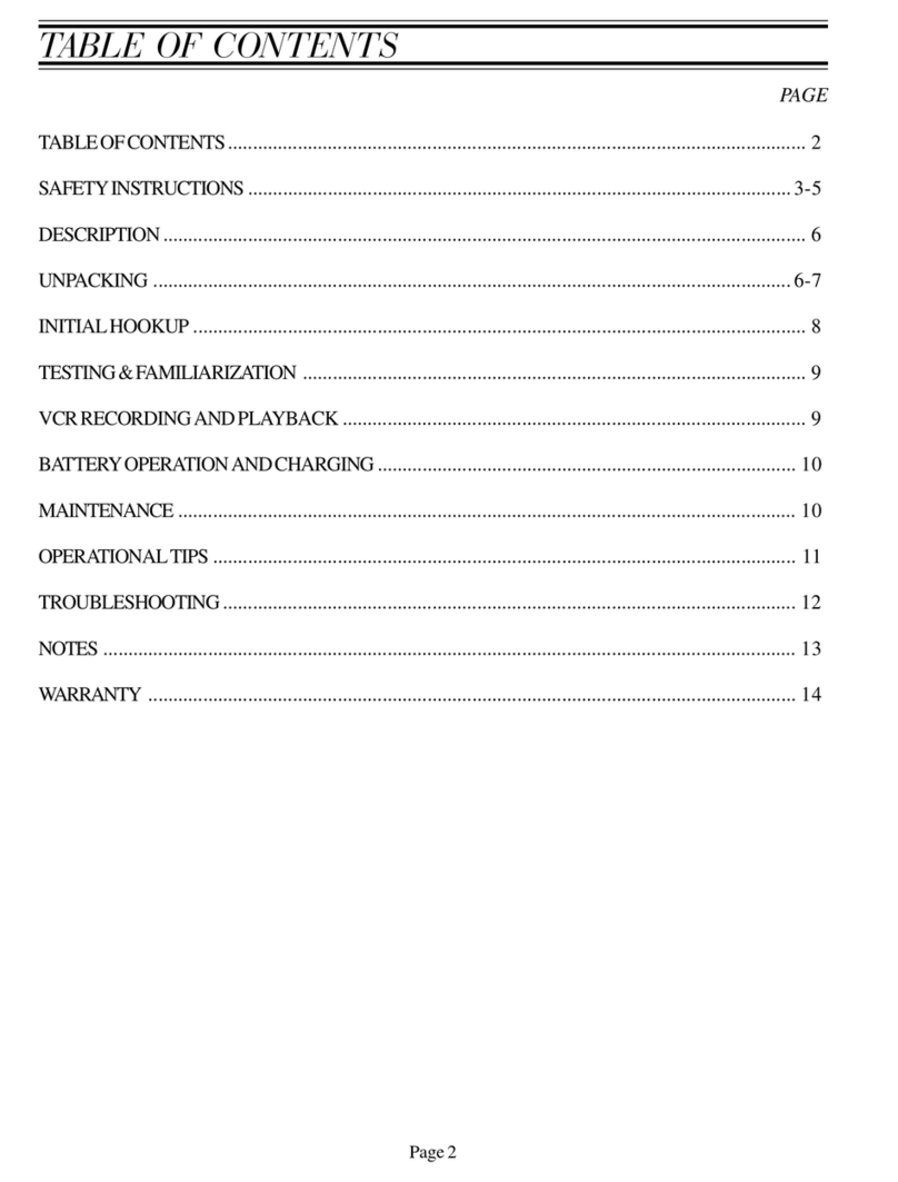
TABLE OF CONTENTS
UNPACKING........................................................................................................... 3
DESCRIPTION....................................................................................................... 3
SAFETY INSTRUCTIONS ..................................................................................3-5
FAMILIARIZATION..............................................................................................6-7
OPERATING INSTRUCTIONS.............................................................................. 8
OPERATIONAL TIPS............................................................................................. 8
BATTERY OPERATION AND CHARGING ........................................................... 9
VCR RECORDING AND PLAYBACK.................................................................... 9
MAINTENANCE.................................................................................................... 10
FLEX-LINK ASSEMBLIES................................................................................... 11
MINICAM & FRAME ASSY..............................................................................12-14
BASKET ASSEMBLY ........................................................................................... 15
TROUBLESHOOTING ......................................................................................... 16

Page3
SPARTAN MINI CAM
VIDEO INSPECTION SYSTEM
INSTRUCTION GUIDE
UNPACKING
Beforesigningtheshippingreceipt, checkandinspect unitforvisible damage.Ifthere isvisibledamage, notesoon
theshippingreceipt.
DESCRIPTION
Thesystem iscomposedofaminiatureclosedcircuittelevisioncameraandcolor LCDmonitor connectedthrough
flexiblepushtype cable.
Thisunit operates on 110 VAC or 12VDCeletrical current, or by battery power.
SAFETYINSTRUCTIONS
WARNING: READ THE “OPERATORS MANUAL” THOROUGHLYBEFORE USINGANYSPARTAN
TOOL PRODUCTS. DRAIN/SEWER CLEANING CAN BE DANGEROUS IF PROPER PROCEDURES
ARE NOT FOLLOWED. KNOW THE PROPER OPERATION, CORRECT APPLICATIONS AND THE
LIMITATIONS OFALLSPARTAN TOOL PRODUCTSBEFORE USE.
CAUTION#1
Useof anyelectrical equipment in a wet environment cancause fatalshock ifequipment isnot properly
grounded,adequately maintained,andif careis not usedby the operator.
A. GROUNDING INSTRUCTIONS—
BeforeusingyourSpartanToolequipment,makesureaproperlygrounded,threeholeelectricaloutletisavailable.
Ifnot,asinsomeolderhomes, use a three-prong adapter and connect the green pigtail (or grounding lug) toa
knowngroundsuchas acoldwaterpipe.Athree- prongadapterisprovidedand availablethroughSpartanTool.
Nevercut off the groundingprong for use in atwo hole outlet receptacle.By doing so, you havecut off your
protectionfrom shock.
SpartanToolequipmentmust be grounded while in use to protecttheoperatorfrom electrical shock. Spartan
Tool equipment comes with a three-conductor cord and three-prong grounding type plug to fit the properly
grounded receptacle. The green (or green and yellow) conductor in the cord is the grounding wire. Never
connectthegreen (or green and yellow) wire to a live terminal. If your unit is for use onlessthat150V,ithasa
plugthat looks like that shown in sketch(A).An adapter,seesketches (B) and (C), is availableforconnecting,
sketch(A)type plugs, to a two-prong receptacle,exceptin Canada.

Page4
Thegreen-colored rigidear(orlug),extending fromtheadapter mustbeconnected toapermanent groundsuch
asaproperlygroundedoutletbox.
Don’t assume that all three-hole outlets are properly installed. Check the outlet and also the
adapter,ifused,withanoutlettestingdevicewhichquicklyindicatesifagroundisconnected.Correctafaultytest
indication before proceeding. The use of a Ground Fault Interrupter is the safest means to check for proper
grounding.
B. EXTENSIONCORDS—
Plugthethree-wirecordfurnishedwithyourmachinedirectlyintoaninspected outlet.If anextension cordmust
beused, it must be ofanapprovedthree-wiretype in good condition, equipped withathree-prongplug.Never
cutoff thegroundingprong forusein atwoholeoutlet receptacle.Bydoing soyouhave cutoffyourprotection
fromshock.
C. OUTDOOR EXTENSIONCORDS —
WhenSpartanToolequipmentisused outdoors,use anextension cordintendedforuseoutdoorsandsomarked.
D. AVOIDELECTRICALCORDSABUSE—
NevermoveorliftSpartanTool equipment by thecord.Donotyankcord at one end to disconnect it from the
receptacle.Keep cordawayfromheat, oilandsharp edges toavoiddamage.Alwaysreplace or repairdamaged
cords.
E. ALWAYSDISCONNECTPOWERCORDWHEN NOTATTENDINGEQUIPMENT—
Whennotinuse,beforeservicingandwhenchangingaccessories,makesureequipmentisnotpluggedin.Never
leavethe unitunattendedwith powerconnected.
F. AVOIDACCIDENTALSTARTING—
Makesureswitchis inthe“off” position beforeplugginginequipment.
G. ALWAYSWEAR RUBBERBOOTSINWETAREAS FORADDED PROTECTION
WARNING: SPARTAN TOOL PRODUCTS ARE NEVER TO BE OPERATED IN AN EXPLOSIVE
ENVIRONMENT.
CAUTION#2
Avoid eye orskin contact withacids orcaustic substanceswhile cleaning drains/sewers.

Page5
A. Alwayswearsafetygoggles whencleaningdrain/sewerstoavoid injurytoeyes.
B. Beforebeginningwork,ask thecustomerif eitheracidsor causticsubstancesare presentinthepipe.If indoubt,
litmuspaper used at the opening of the pipe may give anindicationofthetypeofsubstancein the line. Litmus
paper(acids/caustics)can be purchased at most pharmacies.
C. Exposureto acids or caustic substancescan cause the push cableto break or to becometobrittle. Depending
upon the concentration of acids or caustic substances in the drain/sewer, push cables may break or become
brittleinthedrum,inthepipeorwhenplacingthecablebackintothedrum.Ifthepushcable remainsexposed to
acidsor caustic substances for any lengthoftime,thecable can continue to be damaged.
CAUTION#3
Drains/sewers carry bacteria and the possibility of infectious disease exists, if exposed.
A. Always wear safety goggles and Spartan Tool riveted gloves with rubber gloves inside the riveted gloves to
minimizeexposuretoinfectionfrombacteriainpipes.
B. Avoidcontactwithears,eyes,ormouth withcontents ofpipetolowerthe riskof infection.DONOTSMOKE!
C. Avoidexposinganycutsto drains/sewersandsewer cleaningequipment
CAUTION#4
Followall rulesof safetyand goodhousekeeping.
A. Keep work area clean.
B. Stayalert.
C. Placethe unit and controls in a stable andaccessiblepositionforsafe operation.
D. Properlystorethetools.
E. Keepchildrenawayfromallequipment.
F. Useonlyrecommendedequipmentandaccessories.Maintain toolsin originalworking condition.
G. Do not wear loose fitting clothes.
H. Donot exceedlimitationof equipmentoraccessories.
I. Alwayswear recommendedsafetygear
J. Alwaysliftwithlegs andnotyour back..

Page6
FAMILIARIZATION
BegintofamiliarizeyourselfwiththeoperationofyourSpartanMini-Camunitbyinvestigatingthecontrolsmounted
insidethe case andonthemonitor.
CONTROLS
!FOOTAGE COUNTER
-POSITION: movestext to differentlocationsonscreen. (center, each corner, no text).
-RESET: zeroscounter.
!LIGHTS
-LIGHTS: controlsintensityofcameralights.
-COLOR/B&W: limitsmaximumlightintensityforb&wcamera. Positiontoggleswitchto matchtype of
camerahead installed on end of pushrod (color or b&w). Excess heat willdamageb&wcamerahead
ifoperated in colorposition.
!VIDEO
-VIDEO: videooutput jack (for VCR recording).
!BATTERYLEVEL
-LOW: yellowlightindicatesbatteriesneed chargingandsystemwillshutdownshortly(approximately 10
min.to30min.).
-FULLCHARGE:greenlightturnsontoindicatefullcharge. Unitwill tricklechargeifleftpluggedin.
!POWER
-POWER: redlightindicates unitisreceiving power(frombatteriesorAC).
-POWERIN: connect charger /AC power to charge batteries or operate unitonACpower.
Note: move battery switch to off before connecting to or disconnecting from anAC power supply.
-BATTERYswitch: moveleftfor batteryA, rightforbattery B,orcenter positionforOFF. Whencharger
isconnected, both batteriesarechargingregardless of positionofbattery switch.
Note: when switching from one battery to the other, move switch to off, wait 5 seconds, then
switchtotheotherbattery. Thisallowstimefortheunittoshut downproperlybeforerestarting
when the other battery is selected.
!MONITORCONTROLS
-MONITOR: turnsmonitor“on” or “off”.
-MENU: turns menu“on”and “off”.
-BRIGHT: pushtoselect “bright” onmenu.
-TINT: pushtoselect “tint” onmenu.
-COLOR: pushtoselect “color” on menu.
-(+): increases value ofmenuitem selected.
-(-): decreasesvalueofmenuitemselected.

Page7
(Fig. 1)

Page8
OPERATINGINSTRUCTIONS
!LocatetheCOLOR/B&Wtoggleswitch onthe controlpanel. Position switchtomatchthecameraheadyouare
using.
Note:excess heatwill damageb&w camera head if operatedin colorposition.
!FromtheOFFposition onthebattery toggleswitch,select either AorBbattery. Ifusing ACpower,theswitch
will still need to be selected to either A or B battery. The red POWER light should come on indicating it is
receivingpower from eitherthebatteriesorAC.
Note:whenswitching fromone batterytothe other,move switch toOFF,wait 5seconds,then switch
to the other battery. This allows time for the unit to shut down properly before restarting when the
other battery is selected.
!Insertcameraandpush-rod intopipeopening. If usingthefootagecounter,pushinthePOSITIONbuttonuntil
thetext is where you would likeit. Now push intheRESETbuttontozero counter. The display shouldread
000.0ft. Note: whenpullingpush-rodoutofreel,distancewillincrease. Whenpushing push-rod into
reel, distance will decrease.
!Nowadjust thelightintensityofthecameraheadbyturningtheLIGHTS knobuntilthebest possiblepictureis
displayed. Ifneedbe, adjust monitor settings to obtain a better picture.
!Systemis nowreadyforpipe inspection.
Note:when finishedinspectingpipe,besuretocleanpush-rod thouroughlybeforeitispushedthrough
footagecounterrollers. Thiswill ensurebetteraccuracy andlongerlifeof footagecounter.
OPERATIONALTIPS
!Adjustablecenteringskidsare availableforcentering camerainlines upto24" indiameter.
Colorcamera head - Spartan part number: 62002000
Black& white camera head – Spartanpartnumber: 61019400
!Ifyou get stuck in a line, trytorotatethepush-rod by hand first clockwise then counter-clockwise.
!Theuseofa lubricatingagentonthepush-rod itselfcanoftenincreasethe distanceyouare ableto pushtheunit.
Be certain to abide by all regulations regarding the use of oils (such as vegetable or mineral oils) or other
lubricatingadditivesdown drainlines. Also,ifalubricatingagentis beingused,besuretocleanpush-rodbefore
itispushedthrough footagecounterrollers.
!Considerusing awaterrepellant(suchasRain-X)on thecameralensifyou areexperiencingfogging orwater
spottingonthecamera lensinwet lines.
!Ifglare appearsinthepipe, reducethelightintensity onthepower unit.

Page9
BATTERYOPERATIONANDCHARGING
TheSpartanmini-camisdesignedtooperateon one of two 12Voltbatteries, 110Volthouseholdcurrent(AC),or
anautomobileadapter(12VoltDC). Eachbatterywilllastapproximately1-1/2hours,givingtheMini-Cam3 hours
oftotal run timebetweencharges. Note: batteryruntimewillvarydependingonwhichcameraheadisbeing
used(colororblack & white), beacon or without beacon, and the light intensitysetting).Movingthebattery
toggleswitchtothebatteryAor B determines which battery is in use. With the battery toggle switch in the center
(OFF)position,batterypowerisoff. Theyellow“LOW”batterylightwillcomeonwhenthebatteriesneedtobe
charged. Oncethis light comes on, you’ll have approximately 10 to30 minutes of run timeuntil the system will
shutdown.
Thebatteriesare“NOMEM”batteries,whichmeans theywillnotdevelopamemoryandcanbechargedatanytime
afteruse. To chargeboth batteries, connect chargercord toPOWER INoncontrolpanelandplacebattery toggle
switchinthe OFFposition. TheredPOWERlightshouldcomeontosignalthattheunit ischarging. TheMini-Cam
willnow operate and charge both batteries. Whenthegreen“FULLCHARGE” light comes on, both batteriesare
fullychargedandthe charger will now switch to trickle charge. Note: the green “FULLCHARGE” lightwill
onlycomeon whenthecharger ispluggedin.
VCRRECORDINGANDPLAYBACK
!Installa RCA video cable into theVIDEOoutjack(see fig. 1) on Mini-Cam control panel.
!Connectopposite end of RCA video cable into remote VCR “video in” jack.
!WiththeVCR plugged into apowersource,turntheVCR poweron.
!SetVCR to line input mode (refer toVCRownersmanual).
!InsertVHS tape.
!Press record on VCR.
!Thepicture on your Mini-Cam willnowrecordontoVHS tape.
Hint: ifyou arehavingtroublerecording,check tosee iftheVCRisreceiving avideosignalfromMini-Cam. Todo
this,install an RCA video cable into theVIDEOoutjackonthe Mini-Cam control panel and connect the opposite
endof cableto"videoin" onaTVmonitor. SetTVtocorrectline input (refertoTVownersmanual). There should
bethesamepictureontheTVmonitorasisontheMini-Cam monitor. Ifthesamepictureis shown, proper video
signalisbeingsentfromMini-Cam.Refer to your VCR owners manual for recording procedures. If no picture is
shownonTVmonitor, contact SpartanToolforfurther assistance.

Page10
MAINTENANCE
The Spartan Mini-Cam is designed for easy maintenance and trouble free operation. Regular maintenance will
prolongthe lifeoftheproduct. Follow these simpleprocedures:
!Donot store outdoors and do not allow the unit to sitinatruckorautomobileovernight.
!Neveroperate in standing water.
!Aftereach inspection, alwayswashcamera head whilefullyattachedto the flex-link/push-rod. Immersingthe
camerahead independently mayallowwaterto gather inthecameraand cloud the picture.
!Duringretrieval,cleanoffpush-rodthoroughlytoensureaccuracy andlongevityoffootagecounter.
!Cleanfootagecounterrollersusing amild cleaningdetergent.
!Theconnectorsmayaccumulatedirtonthe pinswithprolonged systemuse. Usea cottonswabimpregnated in
adrop of standard alcohol to clean them. Normallyacleanpininsertedinthe receptacle will wipe the internal
contactandmakea goodconnection. Ifthisdoesnot suffice,adropofalcohol canbeinserted inthe badcontact
holeto cleanit.
!Keepall connector threadscleanto ensure proper tightnessandmechanical connection.
!Wash thepush-rod,flex-link, and cameraheadwhen theinspectioniscomplete. Inspect thecleanpush-rodfor
damagesuchaspeel off, deep scratches, cracks, kinks, or any other signs of failure.
Caution: Neveruse a damaged push-rod even ifthe system appears to function properly. Even thesmallest
dropofwaterthat penetrateswill eventuallycorrodethewiresand produceshortsandmalfunctions. Donotuse
electricalorother type of tape to coveracrack or tear in any push-rodofthis system.
!Wipe the camera lenscoverglass clean with soft cloth. Thecover is constructed of specialscratch-resistant,
high-impactglass,andprovidesmaximumtransparencyunderadverseinspectionenvironmentconditions.

Page11
FLEX-LINKASSEMBLIES

Page12
MINICAM & FRAMEASSY

Page13
MINICAM & FRAMEASSY (CONT.)

Page14
MINICAM & FRAMEASSY (CONT.)
Item #
Part #
Description
1 62005700 Frame, Color Mini-Cam
2 61037000 Monitor, Color Mini-Cam
5 61030500 Basket Wiring
6 31030600 Plug, 1-1/4"
7 61016600 Crutch Tip, 3/4" ID
8 61030800 Screw, Socket Head 1/4-20 x 3
9 61030100 Adapter, Slip Ring (Mini-Cam)
10 34002101 Screw, Set 8-32 x 1-1/4"
11 61037700 Push Rod 100' (Detachable)
12 61039000 Plate, Footage Counter
13 61039400 Pin, Guide Roller
14 61039600 Pin, Driver Roller
15 61039200 Roller, Drive
16 61039100 Roller, Guide
17 61039300 Spring, Footage Counter
18 61039700 Bushing, Footage Counter
19 5OH62400 Screw, Socket Head 10-32 x 3/8
20 522102-00 Nut, Nylock 10-24
21 61039800 Screw, Socket Head 10-24 x 1-1/4
24 61040200 Screw, Shoulder 3/16 Dia x 5/16 Lg
26 61040400 Screw, Shoulder 3/8 Dia x 3 Lg
27 62005600 Roller, Centering
28 62005500 Spacer, Spring Holder
29 62005400 Holder, Spring
30 61040300 Screw, Machine 10-24 x 2-34
31 44226400 Heat Shrink Tubing
33 62005900 Hook, Adhesive Back (Velcro)
34 62006000 Loop, Plain Back (Velcro)

Page15
61030500-BASKETASSEMBLY
Item
Number Part
Number Description
1 61030000 Weldment, Basket
2 61030200 Adapter, Monitor
3 61031700 Bearing, Oil Free 1" ID x 1-1/8" OD
4 44257200 External, Retaining Ring 1"
5 61004000 Slip, Ring
6 34002101 Screw, Set 8-32 x 1/4"
7 61030400 Assy, Basket Wiring
8 72711500 Tie, Wire Nylon 8" Black

Page16
TROUBLESHOOTING
TheSpartanMiniCamSystemismodular in design for ease of troubleshooting. If the system is connected as per
factoryinstructionsand stillfails tooperate, usethefollowingtroubleshootingprocedures:
SYMPTOM
POSSIBLE CAUSES
CORRECTIVE ACTION
No picture Monitor power is off Turn monitor power on
No battery power Move battery toggle switch to the left or right battery
Connect charger if batteries are run down
The LEDís for the camera Turn the light intensity knob clockwise. There should
may be turned to low now be a bright glow of light from the camera face,
indicating that the LEDís are powered on.
The picture is dim The light intensity knob may Rotate the light intensity knob clockwise to the
or hard to see not be at full engagement max position
The brightness control for the Adjust the brightness control on monitor
monitor may need adjustment
Water may have accumulated Place camera unit in a warm, dry, climate controlled
in the camera unit environment for 72 hours and then retest
Footage counter text Position of text is in the off Push in the position button until text is displayed
is not displayed on screen position on screen
monitor screen
Footage counter is Rollers my be binding Check rollers to make sure they spin freely
not counting or
counting incorrectly
Rollers may be slipping Clean rollers with a mild cleaning detergent
on push-rod

Page17
NOTES

SPARTAN TOOL L.L.C.
1506W. Division Street
Mendota, IL 61342
(815)539-7411 "(800)435-3866 "Fax (815)539-9786
http://spartantool.com
62005800
AR 4/15/02 ECO7460
LIMITEDWARRANTY
Spartan Tool warrants its equipment to be free from defects in material and workmanship for one year from the date
of purchase. To obtain warranty service, a purchaser should notify Spartan Tool in writing, at the address provided
below, within the warranty period, and Spartan Tool will direct where to take or send the equipment for service. If the
defect is covered by the warranty, Spartan Tool will repair or replace, at its option, the defective equipment, without
charge for labor or materials. (Freight and insurance are the purchaser’s responsibility.)
This warranty is limited to the original retail purchaser and is not transferable. SpartanTool assumes no responsibility
for damage due to the accident, neglect, abuse, tampering or misuse, nor damage from repairs or alterations by others.
This warranty does not cover damage to the equipment resulting from the use of replacement parts other than genuine
Spartan Tool parts.
Spartan Tool’s sole obligation and the original retail purchaser’s exclusive remedy under this warranty shall be for
repair or replacement as described above.ALLOTHER WARRANTIES, WHETHER EXPRESSED OR IMPLIED,
INCLUDING BUT NOT LIMITED TO IMPLIED WARRANTIES OF MERCHANTABILITY AND FITNESS
FOR A PARTICULAR PURPOSE ARE DISCLAIMED. IN NO EVENT SHALL SPARTAN TOOL BE LIABLE
FOR ANY INCIDENTAL OR CONSEQUENTIAL DAMAGES
WARRANTYPOLICY
All parts for the Spartan Cam are generally available for shipment within 2 working days. Emergency next day
shipments can be arranged at the customer’s cost. All parts subject to warranty must be ordered from Spartan
Customer Service (800/435-3866, 7:45 a.m. - 4:30 p.m. Central Time) and must be accompanied by a PO or credit
card number (American Express, Visa and MasterCard) pending determination of cause of failure. Should the item
be warranted, full credit will be issued. Warranty decisions will be made within 5 days of receipt. Send parts to:
Spartan Tool, 1506 West Division Street, Mendota, IL 61342. The customer must list a Spartan provided RGA
number noticeably on the container. Parts without an RGA number will be refused.
Other manuals for Mini Cam
2
Table of contents
Other Spartan Analytical Instrument manuals
Popular Analytical Instrument manuals by other brands

RS Technical Services
RS Technical Services MINI TRACTOR STANDARD Operation manual
Keysight
Keysight 41901A SMD Operation and service manual

VPInstruments
VPInstruments VPFlowScope user manual

Ntron
Ntron OxyTX Operation and installation manual

MasterForce
MasterForce 244-5968 Operator's manual

Delta-T Devices
Delta-T Devices SunScan SS1 user manual

