Spartan TrapJumper User manual

SINCE 1943
FOR TOUGH CUSTOMERS.
PRODUCT MANUAL
Sewer Inspection Camera
© 2020 Spartan Tool LLC
Part #64052025
Spartan Tool LLC |1618 Terminal Road |Niles, Michigan 49120
order by phone 800.435.3866 order online SpartanTool.com

2
INTRODUCTION........................................................................................................4
Important Safety Instructions ...................................................................................................4
Safety Instructions for all Scanprobe Camera Systems............................................................................5
SAFETY INSTRUCTIONS ................................................................................................5
Intended Use ...................................................................................................................6
Labeling........................................................................................................................6
About Your Product.............................................................................................................7
Warnings, Risks, Safety Measures, and Care ......................................................................................7
Before Operation ...............................................................................................................7
Further Measures ...............................................................................................................8
PRODUCT OVERVIEW .................................................................................................10
Coiler ........................................................................................................................ 11
Keypad Layout ............................................................................................................... 11
Explorer Control Box Display .................................................................................................. 12
Settings Menu ................................................................................................................ 14
START-UP GUIDE......................................................................................................15
Camera Connection and Removal ............................................................................................. 15
Connectivity.................................................................................................................. 16
Mounting the Control Box .................................................................................................... 17
Plug / Socket Engagement .................................................................................................... 17
Brake Operation .............................................................................................................. 18
Push Rod Instructions......................................................................................................... 18
Sonde (Locator) Operation .................................................................................................... 19
Connectability................................................................................................................ 19
Charging and Power .......................................................................................................... 20
Charging Procedure .......................................................................................................... 20
Battery Icon Definitions ....................................................................................................... 21
Lithium-Ion Battery Benefits .................................................................................................. 21
Lithium Battery Shipping ..................................................................................................... 21
Battery Maintenance.......................................................................................................... 21
Charging and Recharging ..................................................................................................... 21
General Maintenance ......................................................................................................... 22
Rod Guide .................................................................................................................... 22
Connector and Cable Care .................................................................................................... 22
Cleaning and Maintenance.................................................................................................... 22
Fitting Protective Collar ....................................................................................................... 23
Contents

3
Basic Functions for Basic Recording ........................................................................................... 24
Writing text .................................................................................................................. 24
Date.......................................................................................................................... 24
Time ......................................................................................................................... 24
USER INTERFACE ......................................................................................................24
Counter ...................................................................................................................... 25
Counter Reset ................................................................................................................ 25
Recording .................................................................................................................... 25
Viewing, copy, and deleting recordings........................................................................................ 25
Viewing Recordings........................................................................................................... 25
Deleting Recordings .......................................................................................................... 25
Transferring Files ............................................................................................................. 25
Light Adjustment ............................................................................................................. 26
File Manager ................................................................................................................. 26
Mina Survey ................................................................................................................. 26
WinCan Survey ............................................................................................................... 27
WinCan Connection Setup .................................................................................................... 27
TECHNICAL DATA OVERVIEW ..........................................................................................28

4
Introduction
This user manual is a guide on how to use the TrapJumper camera system appropriately, effectively and reliably. With this in mind it is
important that you read this carefully before using the TrapJumper system. Please read the“safety instructions”section carefully and
follow them precisely to prevent accidental damage to yourself, your colleagues or the TrapJumper itself.
The following pages provide and grant you the authority to undertake certain functions with the TrapJumper camera system. Spartan
Tool, LLC requires you to read this carefully before using the inspection system and the related accessories. It provides important notes
to help you avoid accidents, damage and injury.
CONTACT US
Spartan Tool LLC
1618 Terminal Road
Niles, Michigan 49120
800.435.3866
SpartanTool.com
SYMBOLS
Warning: This safety icon points out dangers to which a risk of
death or injury could occur.
Atex: This symbol is in reference to areas specific to explosion
proof camera systems. This is not applicable for this system!
Caution: This icon points out dangers to which the system may be
damaged or damage could occur to other equipment.
Note: This icon is used to mention or remark on a certain area with
special requirements.
Maintenance: This symbol is used to give information on how the
equipment can be cleaned and maintained to prolong its life and
reduce repairs.
IMPORTANT SAFETY INSTRUCTIONS
WARNING: When using electrical equipment, basic safety precautions should always be followed to reduce risk of
fire, electric shock and personal injury including the following:
READ ALL INSTRUCTIONS
Double Insulation
Double insulation is used throughout this construction with two separate layers of electrical insulation or one double
thickness of insulation between you and the electrical equipment.
CAUTION: WHEN SERVICING, USE ONLY IDENTICAL REPLACEMENT PARTS SUPPLIED BY SPARTAN TOOL, LLC. Repair or
replace damaged cords.

5
Safety Instructions
SAFETY INSTRUCTIONS FOR ALL SCANPROBE CAMERA SYSTEMS
• Power Cord: Do not use any power cord except the one supplied with the unit.
• Lifting: Observe safe lifting procedures when lifting or moving any components of this system.
• Grounding: If the system or any auxiliary components are connected to the power supply, then the external equipment must be
grounded in accordance with the manufacturer's instructions. Failure to comply with this may cause risk of electrocution.
• Power Adapter: The power adapter supplied with the unit is not intended for use in outdoor environments. Do not attempt to
charge or operate the unit from the power supply outdoors.
• Health and Safety: Sewer systems and other watercourses can be a source of biological hazards. Always use the appropriate PPE and
take suitable precautions to prevent infection when using the TrapJumper.
• Checks: Before using the equipment, check all parts to ensure there is NO damage. Thoroughly inspect equipment to determine that
it will operate properly and perform its intended function.
NOTE: When using a TrapJumper, it is critical that the user has received the relevant training and has a detailed
knowledge of the entire contents of the TrapJumper user manual. They must at all times comply with the instructions
in the document.
If you have any questions on the use of the TrapJumper camera system or require any additional information that has
not been covered in this user manual, please contact Spartan Tool, LLC or one of its authorized agents.
1. Lights: The camera LEDs are very bright. Do not look directly at them or point them at other people's eyes when turned on.
2. Operating Temperature:
Battery:
Battery/Cell charging temperature range 50°F to 113°F / +10°C to +45°C
Battery/Cell discharging temperature range -4°F to 140°F / -20°C to +60°C
WARNING: Do not attempt to operate or charge the system outside the recommended temperature
specifications. Exposing the battery to temperatures above 140°F / 60°C may activate safety systems
and cause a permanent battery failure.

6
Safety Instructions
3. Battery:
NOTE: The battery is encapsulated within the Explorer control box and should not be tampered with. In the unlikely
event that the battery is exposed, please read the following instructions carefully.
a. Do not dismantle, open or shred secondary cells or batteries.
b. Do not short-circuit a cell or a battery. Do not store cells or batteries haphazardly in a box or drawer where
they may short-circuit each other or be short-circuited by other metal objects.
c. Do not subject cells or batteries to mechanical shock by dropping or hitting.
d. In the event of a cell leaking, do not allow the liquid to come in contact with the skin or eyes. If contact has
been made, wash thoroughly with clean water and seek medical attention.
e. Do not use any charger except the one specifically supplied with the equipment.
f. Do not leave the equipment on prolonged charge when not in use.
g. Do not expose cells or batteries to heat or fire. Avoid storage in direct sunlight.
h. Seek medical attention immediately if the cell or battery has been swallowed.
i. All replacement batteries must be supplied and installed by Spartan Tool, LLC.
j. Keep cells and batteries clean and dry.
k. After extended periods of storage, it may be necessary to charge and discharge the cells or batteries several
times to obtain maximum performance.
l. Keep this document in a safe place for future reference.
4. Disposal: The operator is solely responsible for the disposal of any equipment at the end of its service
life. Dispose of any battery products in accordance to local regulations.
INTENDED USE
The TrapJumper system was designed to examine pipework and record/report its findings. We at Spartan Tool, LLC hold no
responsibility for further use that is not considered as intended. Do not use the TrapJumper for other purposes. The system cannot be
used in pipelines with potentially explosive atmospheres or medium. Only specifically manufactured equipment maked with the
identification icon, can be used for this purpose.
LABELING
The TrapJumper components are clearly labeled. The label includes model number, serial number, and all certifications. You may require
this information when talking to Spartan Tool, LLC Customer Service, as these can be used when ordering accessories or spare parts for
your product.

7
Safety Instructions
ABOUT YOUR PRODUCT
The TrapJumper system was designed and manufactured as a pipeline inspection camera. All components are manufactured from high
grade materials. A system consists of a control box, color camera, and a push rod reel.
The TrapJumper is designed to survey pipes and sewers up to 40m in length. With a pressure-sealed camera allowing the camera to
be submerged up to 5m deep. The control box allows users to view and record the image, measure and document your findings to an
on-board storage device, overlay text via a keyboard and write a report onsite using the on-board reporting software. All data can be
exported via USB, SD card, wifi or ethernet interfaces.
WARNINGS, RISKS, SAFETY MEASURES, AND CARE
To reduce the risk of injury, all operators and maintenance personnel must read and understand the user manual before operating,
changing accessories, or performing maintenance on this camera equipment. Understanding these instructions will reduce the
risk of injury and damage to equipment and property. Care must be exercised by everyone using, maintaining, or working near this
equipment. They serve for your own safety as well as your coworkers.
BEFORE OPERATION
Risk of harm occurring must be considered before operating the equipment, as these can cause severe or fatal injuries. Please consider
the following:
CAUTION
1. Risk of Explosion!
Explosive atmospheres can be caused by flammable gases, mists or vapors, or by combustible dusts. If there is enough of the
substance, mixed with air, then all it needs is a source of ignition to cause an explosion. Never use a Spartan Tool inspection system
in pipelines that may contain these substances. In order to survey such conditions, contact Spartan Tool, LLC to obtain information
and equipment designed for such circumstances.
2. Environmental Risk!
Cross contamination and risk of infection: Contamination of drinking water sources by sewage can occur when waste water
inspection systems are used in fresh water pipelines. If sewage contaminates drinking water sources, harmful bacterial can cause
disease from the ingestion of micro-organisms such as E-Colia, Giardia, Cryptospordium, Hepatitis A, and Helminths.
Never use an inspection system alternately between waste water and fresh water surveys. Cleaning your inspection system is not
sufficient. Always use a separate unit dedicated for that particular environment.
Risk of infection and illnesses are not uncommon. Although mild cases of gastroenteritis and potentially fatal diseases, such as
leptospirosis (Weil's disease) and hepatitis do pose a serious risk.
To reduce the chances of contracting these diseases when surveying sewage pipelines ensure that employees and line
management understand the risks through proper instruction, training and supervision.
Provide suitable personal protective equipment, which may include waterproof/abrasion resistant gloves, footwear, eye and
respiratory protection. Face visors are particularly effective against splashes. Speaking to your doctor for preventative injections and
advice is recommended.

8
Safety Instructions
3. Electric Shock
Risk of death by electric current.
• Check the connector cable and push rod for damage, such as kinks or crushed areas. If damage has occurred, disconnect the
power supply immediately. Safeguard the socket against renewed connection and inform Spartan Tool, LLC Customer Service
Team or an authorized repair center.
• Ensure no liquid can enter the control box. Fit all rubber blanking bungs and check connector facia rubber flap is closed tight
when operating in the rain. When survey is finished, wipe the rubber keypad dry and leave the lid open in a warm environment
to allow any condensation to evaporate. Should any water penetrate the box, do not connect the power cords and inform
Spartan immediately.
• All work on the electrical system can only be carried out by Spartan Tool, LLC or authorized repair centers. If any work exceeds
the tasks described in the Maintenance chapter, please contact Spartan Tool, LLC for assistance.
4. General Precautions/Risks
As with all work, accidents can happen. Please keep the following in mind before any work is carried out. Stay vigilant at all times,
be aware of your surroundings and use the correct personal protetctive equipment—tools, warning signs, barriers, etc.
RISK DETAILS OF SPECIFIC HAZARD
CONFINED SPACE
• Working in a confined space (manhole/drain)
• Lowering and raising operatives via tripod and winch
Lack of oxygen
Unconsciousness
Suffocation
SLIPS, TRIPS, AND FALLS
• Trailing hoses / cords
• Storage of materials
• Blocked access and egress
• Collision with materials and equipment Public Safety
Bruising
Cuts
Sprains
Fractures
MANUAL HANDLING
• Lifting of manhole covers
• Use of hand tools
• Handling and use of equipment
Prolapsed disc injuries (back)
Damage to muscles, ligaments, and tendons
Hernias
Cuts, bruises, and fractures
Burns
EXPOSURE TO ASBESTOS
Shortness of breath
Plural plaques
Asbestosis
Lung cancer
Mesothelioma
EXPOSURE TO NOISE AT WORK Short-term damage to hearing
FURTHER MEASURES
The TrapJumper system was designed and engineered to the highest standards to the guidelines of safety engineering regulations.
Nevertheless, accidents can happen, that could endanger life, the health of its users or third parties and could damage the inspection
system itself as well as other machinery.
The user assigned to operate the inspection system must have read and understood the user manual completely before any work is
carried out.

9
Safety Instructions
WARNING
1. Users of the inspection system should work as safely and risk-free as operationally possible. The following
measures will help achieve this:
• Regularly inspect and perform any maintenance as required
• Ensure all personnel follow the safety guidelines laid out in this manual at all times.
• Keep up to date with any training courses.
• Always have the instruction manual available when using the inspection system.
2. Personal Safety: Any users of the inspection system, whether it's to operate, maintain or set up the equipment,
must be fully trained or instructed by an expert. Fully trained operators have sufficient knowledge of the
inspection system through their technical training and experience. They would also be familiar with the
appropriate health and safety regulations as well as accident prevention, giving them the knowledge to operate
the inspection system within safe working conditions.
• Read, understand, and follow all safety requirements specified in this instruction manual
• Carry out a risk assessment prior to any work
• Observe the relevant accident prevention regulations
• Attend and pass any site induction, if required
• Be instructed on the handling of any dangerous goods
• Be vigilant at all times of your work space and surrounding area
3. Avoid damage to property. As the operator of the TrapJumper system, it is your responsibility for the following:
• Do not use the TrapJumper outside the parameters of "intended use" (see page 6)
• Observe the operating conditions for this camera system as noted in this instruction manual
• Keep the equipment clean and in full working order. See cleaning instructions.

10
Product Overview
The TrapJumper system consists of the following components:
1. System box
2. Coiler
3. Push rod
4. Camera head
The following sketch demonstrates a typical set-up:
1
2
3
4

11
1. Push rod
2. Coiler brake
3. Explorer control box
mounting plate
4. Nylon rod guide
5. Sonde ON/OFF
6. Monitor lead
7. Handle
Product Overview
1
2
3
4
5
6
7
KEYPAD LAYOUT
1. Help button
2. mina survey
3. Wincan survey
4. General text overlay
5. Text font
6. Text size
7. Meterage placement
8. File manager
9. Settings
10. Sonde ON/OFF button
11. Lights OFF
12. Power ON/OFF
13. Lights down
14. Lights up
15. Video functions
16. Snapshot
17. Footage counter reset
18. Navigation keys
19. QWERTY keyboard
COILER
1
2345678910
11 12
13
14
15
16
17
18
19
12
Product Overview
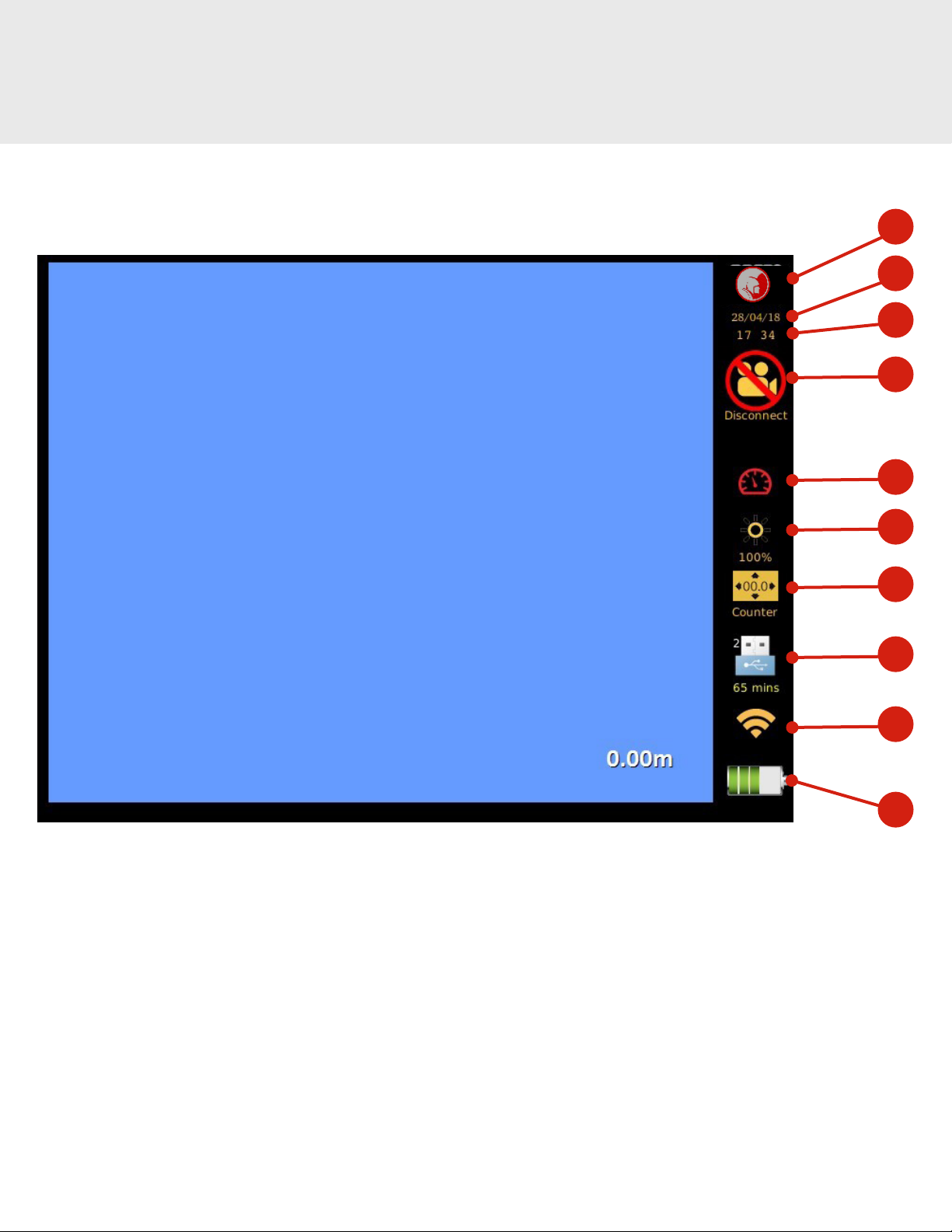
1. Function display: this allows users to determine what mode you're in, i.e. Wincan, mina, etc.
2. Date: used on a survey file as a reference
3. Time
4. Camera connectivity: informs you if there is a camera present
5. Pressure status: (not applicable with TrapJumper) this allows users to determine whether the camera is water-tight
6. LED brightness: indicates the level of brightness
7. Counter placement: allows the user to position the counter anywhere on the screen and change the font/size
8. Storage device: indicates the device to which your files are stored to
9. Wi connection
10. Battery status: ref. charge procedure
EXPLORER CONTROL BOX DISPLAY 1
2
3
4
5
6
7
8
9
10

13
Product Overview
Camera
connected
Recording
Pressure ok
Sonde
switched ON
Sonde
frequency

14
SETTINGS MENU
The Settings Menu allows users to access the mainframe of the TrapJumper system. The status menu can be accessed through the
settings, which provides a health check of the components. Users can adjust the time/date, connect to WinCan Web, and view the
camera temperature/pressure.
Product Overview
System
details
TemperaturePressure
sensor 2
Pressure
sensor 1
Onscreen
counter
settings
Monitor settings &
software update menu Wifi
connection WinCan
Web & FTP WinCan
settings
NOTE: The pressure sensors and temperature are not applicable for the TrapJumper system.
15
Start-Up Guide
The following guide offers instructions on how to set up your TrapJumper system correctly and safely. Please read these instructions in
full before the system is set up. Your TrapJumper system has been built to your specification, the camera and overall setup remains the
same. Please pay close attention to any Notes and Warnings.
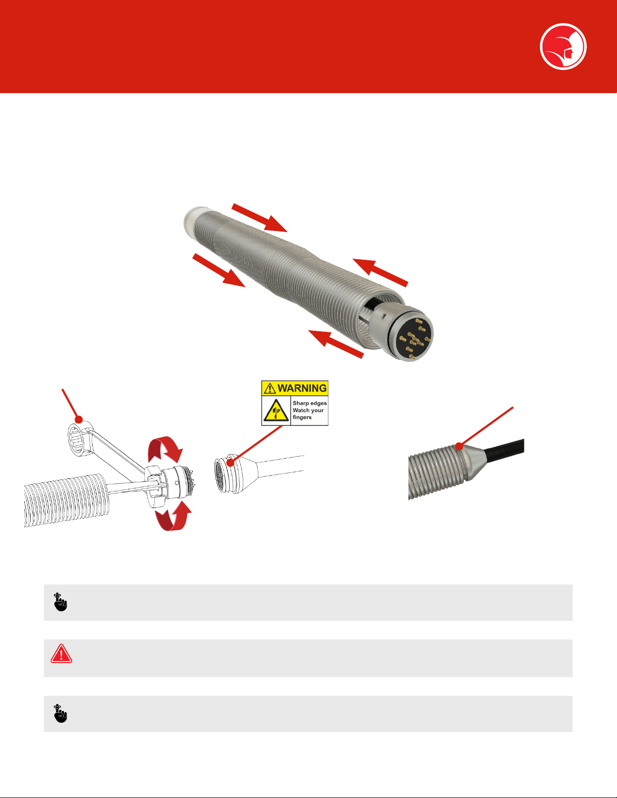
CAMERA CONNECTION AND REMOVAL
1. Compress the spring together to reveal
the connector.
2. Using a 12mm wrench (as below), screw
the male connector into the rod.
Spring end
12mm Wrench
Tighten
Loosen
3. Finally, screw the spring over the rod
connector hand tight.
Repeat this process in reverse to remove the camera head.
NOTE: If the spring is difficult to unscrew when removing the camera, use the camera removal tool provided in the
accessory kit. Align the inner tool with the end of the spring (see above) and apply the required force.
WARNING: Wear gloves! The spring thread contains sharp edges and should not be touched without hand
protection. Take care with the connector thread and avoid extreme force. Do not over tighten!
NOTE: Always ensure the connector is clean and the electrical contacts remain grease free at all times.

16
CONNECTIVITY
Start-Up Guide
USB (1)
USB (2)
SD Card Socket
Ethernet Socket
Headphones
Microphone
Pressure valve
Monitor lead
input socket (10 pin)
Identification label
VGA output
Battery charging
socket
Monitor lead input
socket (7 pin)
Battery light
indicator
17
Click!
Start-Up Guide
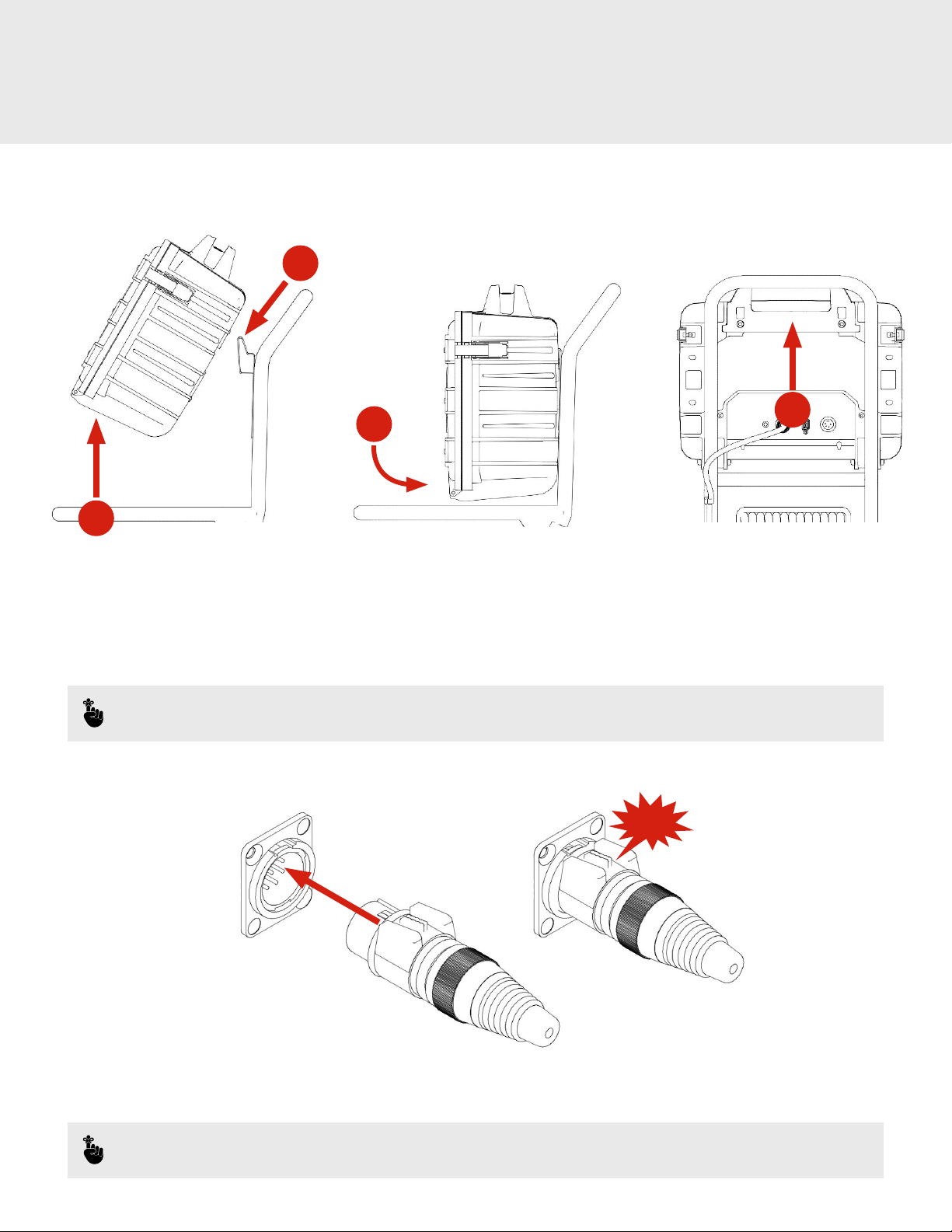
MOUNTING THE CONTROL BOX
1
2
34
1. Lift box at an angle above the mounting plate.
2. Align the base of the handle and clip over the plate.
3. Lower box against the handle.
4. Check the box is central to the frame.
NOTE: To remove the box, disconnect the cables and repeat the steps above in reverse.
PLUG / SOCKET ENGAGEMENT
7 pin-din:
• Align the keyway clip at 12 o'clock with the socket
• Push connector into the socket until you hear the click of it locating
NOTE: Please ensure all connectors are clean and dry before connection. Do not twist.

18
Start-Up Guide
BRAKE OPERATION
Lock
Release
WARNING: Be careful your hands don't get trapped or pinched.
• Turn the handle counterclockwise to release reel and clockwise to apply the brake.
PUSH ROD INSTRUCTIONS
• When loading the push rod onto the frame, be sure to align the rod and do not cross it over. This will reduce the risk of damage and
an imprecise meterage reading.
CAUTION: Excessive force on the push rod will cause damage and can even snap the inner cores. Do not over exert
when surveying or reeling back onto the coiler. Different push rods are designed for different environments; be
sure the rod you are using is fit for the pipe it's being used on. If you are unsure, contact Spartan Tool, LLC for help
and advice.

19
Start-Up Guide
SONDE (LOCATOR) OPERATION
Sonde ON/OFF
button
• Engage the push button to turn on the 512 Hz sonde.
• The red light will illuminate to indicate the sonde is active.
CONNECTABILITY
CAUTION: When connecting or disconnecting any cables or cameras, ensure the system is switched off and
disconnected from power supply.
• Do not expose mains cables/charges to rain or moisture.
• Keep all power cables clean. Contamination will increase the risk of electric shock.
• Connect all cables in accordance with the connector diagram.
• Check charging cables are not damaged. Do not use if damage is located. Purchase a new replacement from
Spartan Tool, LLC or a recommended repair center.
No. Description Part No.
1TrapJumper Camera 1024-1002-0
2TrapJumper Coiler 1024-1001-0
3Explorer Control Box 6405CBOX

20
Start-Up Guide
CHARGING AND POWER
1
23
4
5
1. 230v Power lead
2. 110v Power lead (64051697)
3. 24v Explorer control supply PSU
4. 12v Car charger (64051821)
5. Explorer control box (6405CBOX)
NOTE: Observe power voltage: the voltage of the power source must correspond with the information provided on
the equipment or power supply label.
CHARGING PROCEDURE
To begin charging, insert the power supply or car charger into the battery charging socket (connect to a source with a power cord using
PSU). Charging begins as soon as power is connected. The charging procedure automatically recognizes the charge state of the battery.
Charge current will fluctuate according to the battery temperature and voltage. This protects the battery, which is always fully charged
when connected to a power source.
• Explorer control box, estimated battery life: 9 hours
• Explorer control box, estimated charging cycle: 4 hours
• Battery indication light will flash red and an alarm will sound to warn of low battery power.
NOTE: Batteries and life cycles are given as estimates. To increase the batteries' life, health and longevity, please read
the battery maintenace section.
Table of contents
Other Spartan Analytical Instrument manuals


