Spartan Mini Cam Setup guide

Page 1
( 8 0 0 ) 4 3 5 - 3 8 6 6
SPARTAN TOOL L.L.C.
S p a r t a n M i n i C a m
V i d e o I n s p e c t i o n S y s t e m
Owners Instruction Manual

Page 2
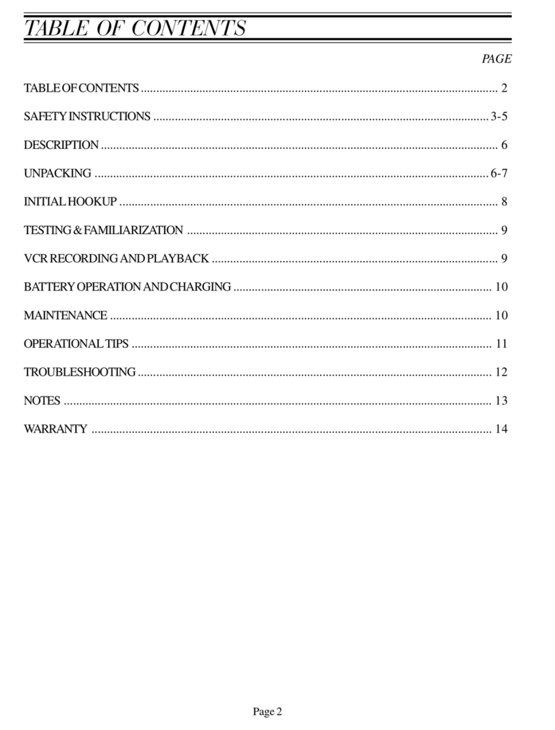
Table of Contents
Operating Section
Unpacking .................................................................................................................................... 3
Description ................................................................................................................................... 3
Safety Instructions ..................................................................................................................... 3-5
Familiarization ........................................................................................................................... 6-8
Monitor Control Panel ........................................................................................................ 7
VCR Control Panel ............................................................................................................ 8
Battery Operation & Charging ...................................................................................................... 9
VCR Recording and Playback .................................................................................................... 10
Recording ........................................................................................................................ 10
Playback .......................................................................................................................... 10
Video Head Cleaning....................................................................................................... 10
Microphone Operation .................................................................................................................11
External Video Reel (Optional) .............................................................................................. 11-13
Installing Push Cable Into Distance Counter ................................................................... 12
Removing Push Cable From Distance Counter ............................................................... 12
Setup Instructions ............................................................................................................ 13
Operating Instructions ................................................................................................................ 14
Operational Tips ......................................................................................................................... 14
Maintenance ............................................................................................................................... 15
Mini-Cam Troubleshooting ......................................................................................................... 16
VCR Troubleshooting ................................................................................................................. 17
Flex-Link Compression Tool (Optional) ................................................................................. 18-21
Parts Section
Final Assembly - 62013000 ................................................................................................... 22-23
Reel Assembly - 62012400 ................................................................................................... 24-25
Distance Counter Assembly - 62012500 ............................................................................... 26-27
Basket Assembly - 61030500 ..................................................................................................... 28
Detachable Flex-Link Assemblies .............................................................................................. 30
Internal Push Cable Assembly ................................................................................................... 31
External Push Cable Assemblies (Optional) ............................................................................... 31
Slip Ring Assembly - 62009200 (Optional) ................................................................................. 32
Removing and Reinstalling Slip Ring Assy ................................................................................. 33
Video Reel Frame Assembly - 62009000 (Optional) ............................................................. 34-35
Video Reel Drum Assembly - 61016700 (Optional) .................................................................... 36
Distance Counter Assembly - 62008000 (Optional) ................................................................... 37

Page 3
Unpacking
Before signing the shipping receipt, check and inspect unit for visible damage. If there is visible
damage, note so on the shipping receipt.
Description
The system is composed of a miniature closed circuit television camera and color LCD monitor
connected through flexible push type cable.
This unit operates on battery power, 110 Volt AC electrical current, or 12 Volt DC eletrical current.
Safety Instructions
WARNING: READ THE “OPERATORS MANUAL” THOROUGHLY BEFORE USING ANY SPARTAN
TOOL PRODUCTS. DRAIN/SEWER CLEANING CAN BE DANGEROUS IF PROPER
PROCEDURES ARE NOT FOLLOWED. KNOW THE PROPER OPERATION, CORRECT
APPLICATIONS AND THE LIMITATIONS OF ALL SPARTAN TOOL PRODUCTS BEFORE USE.
CAUTION #1
Use of any electrical equipment in a wet environment can cause fatal shock if equipment is
not properly grounded, adequately maintained, and if care is not used by the operator.
A. GROUNDING INSTRUCTIONS —
Before charging your Spartan Minicam, make sure a properly grounded, three hole electrical
outlet is available. If not, as in some older homes, use a three-prong adapter and connect the
green pigtail (or grounding lug) to a known ground such as a cold water pipe. A three- prong
adapter is available through Spartan Tool. Never cut off the grounding prong for use in a two
hole outlet receptacle. By doing so, you have cut off your protection from shock.
The Spartan Minicam must be grounded while charging or operating using the 110V power cord
to protect the operator from electrical shock. The Spartan Minicam comes with a three-conductor
cord and three-prong grounding type plug to fit the properly grounded receptacle. An adapter,
see sketches (B) and (C), is available for connecting, sketch (A) type plugs, to a two-prong
receptacle, except in Canada.

Page 4
Safety Instructions (cont)
The green-colored rigid ear (or lug), extending from the adapter must be connected to a
permanent ground such as a properly grounded outlet box.
Don’t assume that all three-hole outlets are properly installed. Check the outlet and
also the adapter, if used, with an outlet testing device which quickly indicates if a ground is
connected. Correct a faulty test indication before proceeding. The use of a Ground Fault
Interrupter is the safest means to check for proper grounding.
B. EXTENSION CORDS —
Plug the power cord attached to the Minicam directly into an inspected outlet. If an extension
cord must be used, it must be of an approved three-wire type in good condition, equipped with
a three-prong plug. Never cut off the grounding prong for use in a two hole outlet receptacle. By
doing so you have cut off your protection from shock.
C. OUTDOOR EXTENSION CORDS —
When Spartan Tool equipment is used outdoors, use an extension cord intended for use outdoors
and so marked.
D. AVOID ELECTRICAL CORD ABUSE —
Never move or lift Spartan Tool equipment by the cord. Do not yank cord at one end to disconnect
it from the receptacle. Keep cord away from heat, oil and sharp edges to avoid damage. Always
replace or repair damaged cords.
E. ALWAYS WEAR RUBBER BOOTS IN WET AREAS FOR ADDED PROTECTION
WARNING: SPARTAN TOOL PRODUCTS ARE NEVER TO BE OPERATED IN AN EXPLOSIVE
ENVIRONMENT.
CAUTION #2
Avoid eye or skin contact with acids or caustic substances while inspecting drains/sewers.
A. Always wear safety goggles when inspecting drain/sewers to avoid injury to eyes.

Page 5
Safety Instructions (cont)
B. Before beginning work, ask the customer if either acids or caustic substances are present in the
pipe. If in doubt, litmus paper used at the opening of the pipe may give an indication of the type
of substance in the line. Litmus paper (acids/caustics) can be purchased at most pharmacies.
C. Exposure to acids or caustic substances can cause the push cable to break or to become to
brittle. Depending upon the concentration of acids or caustic substances in the drain/sewer,
push cables may break or become brittle in the drum, in the pipe, or when placing the cable
back into the drum. If the push cable remains exposed to acids or caustic substances for any
length of time, the cable can continue to be damaged.
CAUTION #3
Drains/sewers carry bacteria and the possibility of infectious disease exists, if exposed.
A. Always wear safety goggles and Spartan Tool riveted gloves with rubber gloves inside the riveted
gloves to minimize exposure to infection from bacteria in pipes.
B. Avoid contact with ears, eyes, or mouth with contents of pipe to lower the risk of infection. DO
NOT SMOKE!
C. Avoid exposing any cuts to drains/sewers and sewer inspecting equipment
CAUTION #4
Follow all rules of safety and good housekeeping.
A. Keep work area clean.
B. Stay alert.
C. Place the unit and controls in a stable and accessible position for safe operation.
D. Properly store the tools.
E. Keep children away from all equipment.
F. Use only recommended equipment and accessories. Maintain tools in original working condition.
G. Do not exceed limitation of equipment or accessories.
H. Always wear recommended safety gear
I. Always lift with legs and not your back.

Page 6
Familiarization
EXTERNAL PUSH
CABLE CONNECTOR
MICROPHONE
SENSOR
SUN SHIELD
P/N: 62013200
5.6” LCD MONITOR
VCR
110V AC & 12V DC
POWER CORDS
FLEX-LINK
HOLDERS
TELESCOPING
HANDLE
100’ INTERNAL
PUSH CABLE
12V DC POWER
CORD P/N: 61032100
110V AC POWER
CORD P/N: 61032000
AC POWER
CORD FUSE

Page 7
Familiarization (cont)
MONITOR CONTROL PANEL
POWER
ON/OFF: Turns Minicam power ON or OFF.
ON – Red light indicates unit is powered on.
FULL CHARGE – A steady green light indicates unit is
fully charged. A flashing green light indicates unit is
charging.
DC LOW – Yellow flashing light indicates unit is
operating on low voltage and needs to be charged.
When the yellow flashing light turns into a solid yellow
light, the unit has approximately 30 seconds before it
shuts down. Once the unit shuts down, you can press
the power button to turn the unit ON for an additional
30 seconds. This may be used for critical situations
that require finishing the pipe inspection.
LIGHTS
MIN: Decreases light intensity
MAX: Increases light intensity
COUNTER
POS: Positions text in different locations on screen. (center, each corner, no text)
RESET: Zeros counter.
MIC
MIC: Turns microphone on or off.
BLUE LED – Indicates microphone is recording.

Page 8
Familiarization (cont)
VCR CONTROL PANEL
1. Cassette Compartment
The power is on automatically when the cassette is inserted even if the power was off. When the cassette is
inserted, Auto Tracking Adjustment operates automatically.
2. Power Key
When the Minicam is powered on, the power indicator lamp will always light up in red.
The Power On and Power OFF mode
will be toggled by pressing this key.
When the POWER is switched on,
the power lamp will light up in red
and the other keys will light up in
green.
3. Cassette-In Lamp
When the cassette is inserted, the
CST-IN lamp will light up in green.
4. Eject Key
Press this button to eject tape.
5. Stop Key
Press this button to stop tape.
6. Rewind Key
If this key is pressed in the PLAYBACK mode, the VCR enters the reverse picture search mode, and “REW”
indicator lamp will be blinked.
If pressed in STOP mode, then the tape will rewind at high speed, the indicator lamp will light up in red.
7. Play / Re-Auto Tracking
Press this key to playback a recorded tape, or to release special operation such as the search mode.
In the PLAYBACK mode the playback indicator lamp will be lit in red and Auto Tracking will be displayed on the
monitor screen.
When the playback picture is noisy, press this key to operate Re-Auto Tracking.
8. Fast Forward / Cue Key
If this key is pressed in the PLAYBACK mode, the VCR enters the forward picture search mode, and “FF”
indicator lamp will be blinked.
If pressed in STOP mode, the tape will fast forward at high speed and the indicator lamp will light up in red.
9. REC Key
Press the REC key for at least one second to start recording.
10. DEW/HEAT Lamp
When power is on, this indicator flashes red to indicate excessive moisture buildup inside the VCR.
The unit will not operate until it dries out sufficiently (the tape can be ejected from the unit).
When DEW mode has been activated, leave the unit on and allow it to dry out completely.
11. Hi-Fi Lamp
In the Hi-Fi out mode, the lamp will light up in red.
12. Auto Repeat Lamp
Not Available.
13. Audio/Video in Jacks
Not Available.

Page 9
Battery Operation & Charging
BATTERYOPERATION
The Spartan Minicam is designed to operate using internal battery power, 110V AC (household
current), or 12V DC (automobile). A fully charged battery will last approximately 4 hours. When
using the VCR, the battery will last approximately 2 hours. NOTE: Battery run time will vary
depending on which camera head is being used (color or black/white), beacon or non-beacon, and
the light intensity setting. The yellow DC LOW light will begin to flash when the battery begins to
run low. When the flashing yellow light changes to a solid yellow light you will have approximately
30 more seconds before the unit shuts down. If the unit shuts down, you can power the unit up for
an additional 30 seconds by pressing the POWER ON button. This feature may allow you to finish
the pipe inspection in critical situations.
BATTERYCHARGING
110V AC – To charge the internal battery using a 110V power source you will need to uncoil
the 110V power cord (see Pic. 1) and plug the end into a 110V electrical outlet. The green
FULL CHARGE light will begin to flash indicating that the unit is being charged. When the
green FULL CHARGE light turns into a solid green light, the unit is fully charged. Once the
batteries are fully charged, the battery charger will automatically switch to trickle charge.
12V DC – To charge the internal battery using a 12V DC power source you will need to
uncoil the 12V DC power cord (see Pic. 1) and plug the end into an automobile power port
(cigarette lighter). The green FULL CHARGE light will begin to flash indicating that the unit
is being charged. When the green FULL CHARGE light turns into a solid green light, the unit
is fully charged. Once the batteries are fully charged, the battery charger will automatically
switch to trickle charge.
Battery Recharge Time: Approximately 4-6 hours.
NOTE: When using the 12V DC power cord to charge the Minicam, make sure to unplug the
12V DC power cord from the automobile power port before starting the vehicle.
12V DC
POWER CORD
P/N: 61032100
110V AC POWER CORD
P/N: 61032000
Pic. 1

Page 10
VCR Recording and Playback
To use the built in VCR follow the steps below.
RECORDING
1. Insert a VHS tape into the cassette compartment. The VCR will automatically power on.
2. Press the POS button to position the distance counter text in a location other than the upper left corner of
the monitor screen. NOTE: During recording, the distance counter text will be recorded and displayed on
the monitor screen during playback. If you do not want the distance counter text to be recorded, press the
POS button until the text is not shown on the screen.
3.When you are ready to begin recording, press the REC button. The REC button will light up in red and the
text REC will appear in the upper left corner of the monitor screen to indicate the unit is recording.
4. To end recording, press the STOP button. The word STOP will appear in the upper left corner of the
monitor screen to indicate the unit is no longer recording.
NOTE: To use the microphone feature, refer to the section below titled “Microphone Operation”.
PLAYBACK
1. To view a previously recorded tape, insert the VHS tape into the cassette compartment.
2.Press the PLAY button. The PLAY button will light up in red and the word PLAY will appear in the upper left
corner of the monitor screen. The recorded image should now be displayed on the screen. NOTE: This
VCR features an auto tracking feature that will adjust the tracking automatically when a taped is played.
3.To rewind or fast forward during playback, press the REW or FF button. The chosen button will blink in red
and no text will be displayed on the monitor screen. For faster rewinding or fast forwarding, stop the tape by
pressing the STOP button and then press either the REW or the FF button. The chosen button will light up
in red and the proper text will be displayed on the monitor screen. The tape will now rewind or fast forward
at high speed.
NOTE: If the microphone feature was used during recording, the sound will not be heard during
playback on the Minicam. You must use a VCR that is hooked to an audio/video source such as a
home television.
VIDEO HEAD CLEANING
The video heads enable the VCR to read video information pictures from the tape during playback. In the
unlikely event that the heads become clogged with dirt video playback will be impossible. This can easily be
determined during playback of a known good tape, there is good sound, but the picture is extremely snowy.
If this is the case, contact Spartan Tool.
NOTE: During normal operation of the VCR, the video and audio heads can accumulate dirt over a period of
time, especially when using an old or poor quality tape. When the heads are dirty, the picture can get snowy
and the tracking control will have little or no effect. If this condition occurs, head cleaning cartridges may
take care of the problem and restore normal picture. We recommend that head cleaning cartridges be used
sparingly since they are very abrasive and can damage the video heads during prolonged use. If the problem
is not resolved with the head cleaning cartridge then contract Spartan Tool.

Page 11
Push Rod with
Flex-link and
camera
Distance
Counter
Assy
Slip Ring
Assembly
t
t
t
Drain Hole
Drain
Hole
Drain Hole
Microphone Operation
The Spartan Minicam is equipped with a built-in, hands-free, super sensitive microphone. To use this feature,
follow the steps below.
1. Begin recording using the built-in VCR. (Refer to section titled VCR Recording and Playback).
2. Press the MIC button on the monitor control panel. The blue light next to the button will illuminate
to indicate the microphone is now recording.
3. Start recording your voice. NOTE: The microphone sensor is very sensitive.
4. When finished recording your voice, press the MIC button to turn the microphone off. The blue
light should no longer be illuminated.
External Video Reel (Optional)
The Spartan Minicam has the ability to connect to an external Spartan video reel. This feature allows you to use a stiffer
push-cable at longer lengths (up to 300 feet). To use this feature, you will need to purchase a Spartan video reel
assembly and a 15’ patch cable to connect the external video reel to the Minicam.
{
Qty
Req'd
Part
Number Description
62009115 Video reel assembly with 150’ push-cable
62009120 Video reel assembly with 200’ push-cable
62009125 Video reel assembly with 250’ push-cable
62009130 Video reel assembly with 300’ push-cable
1 61042400 15’ Patch cable
1
Reel (Back View) Reel (Front View)
15’ Patch Cable

Page 12
External Video Reel (Optional)
INSTALLING PUSH CABLE INTO DISTANCE COUNTER:
1. Loosen Adjusting Knob on Counter Assembly. (See Fig. 1)
2. Lift Swing Bolt up, and then rotate clockwise until the Swing Bolt is out of the Adjusting Block Seat. Allow the Roller
Arm Assembly to swing downwards until it contacts the stop pin. (Refer to Fig. 1 & 2)
3. Remove the Camera/Flex-link end of the push cable from inside the reel and position push cable above the Guide
Roller and Support Roller. (Refer to Fig. 2)
Figure 4Figure 3
Jam Nuts
Counter Drive Rollert
t
Guide Roller
Figure 2
Figure 1
t
t
t
t
Adjusting Knob
Adjusting Block Seat
Swing
Bolt
Roller Arm Assembly
t
Guide Roller
t
Support Roller
4. Seat the push cable in the groove of the Guide Roller and then rotate Roller Arm Assembly upwards until push cable
is in contact with Counter Drive Roller. (See Fig. 3) Now rotate Swing Bolt counter-clockwise into Adjustment Block Seat
and hand tighten Adjusting Knob until Jam Nuts contact the lower surface of the Adjustment Block Seat. (Refer to Fig.
4)
REMOVING PUSH CABLE FROM DISTANCE COUNTER
1. Loosen Adjusting Knob on Counter Assembly.
2. Lift Swing Bolt up, and then rotate clockwise until the Swing Bolt is out of the Adjusting Block Seat. Allow the Roller
Arm Assembly to swing downwards until it contacts the stop pin.
3. Remove push cable from counter assembly and place the camera/flex-link end of push cable inside reel for storage.
4. Rotate Roller Arm Assembly upward and then rotate Swing Bolt counter-clockwise into Adjustment Block Seat.
5. Hand tighten Adjusting Knob until Jam Nuts contact the lower surface of the Adjustment Block Seat.
6. Unit is now ready for transportation.

Page 13
External Video Reel (Optional)
SETUP INSTRUCTIONS
1. Turn the Minicam power off.
2. Using the 15’ patch cable connect the female end (no pins) to the male connector (pins exposed) on the external
video reel. (See Pic. 2)
3. Connect the other end of the 15’ patch cable to the external video reel connector on the Minicam. (See Pic. 3)
4. After both ends of the 15’ patch cable are connected, press the power button to turn the Minicam on. The Minicam
will automatically switch to the external video reel. The image on the monitor should now be coming from the
external video reel.
5. The unit is now ready for pipe inspection using the external video reel.
Pic. 2 Pic. 3
15’ PATCH CABLE
FEMALE END
(NO PINS)
MALE
CONNECTOR
EXTERNAL
VIDEO REEL
CONNECTOR

Page 14
Operating Instructions
1. Flip the monitor lid up and open the sun shield for maximum viewability.
2. Press the POWER ON/OFF button to turn the unit on. The red LED should light up to indicate
that the unit is powered up.
3. Insert camera and push-cable into pipe opening.
4. Adjust the light intensity of the camera head by pressing either the MIN or MAX button. NOTE:
You can either press the button repeatedly or hold the button in.
5. To use the distance counter, press the POS button until the text is in a desirable location. Now
press the RESET button to zero the counter. The display should read 000.0 f (feet) with 000.0
m (meters) directly below it. NOTE: When pulling the push-cable out of the reel, the distance
will increase. Pushing the push-cable back into the reel will cause the distance to decrease.
6. System is now ready for pipe inspection.
Operational Tips
Adjustable centering skids are available for centering camera in lines up to 24" in diameter.
Color camera head - Spartan part number: 62002000
Black & white camera head – Spartan part number: 61019400
If you get stuck in a line try to rotate the push-cable by hand first clockwise then counter-
clockwise.
The use of a lubricating agent on the push-cable itself can often increase the distance you are
able to push the unit. Be certain to abide by all regulations regarding the use of oils (such as
vegetable or mineral oils) or other lubricating additives down drain lines. Also, if a lubricating
agent is being used, be sure to clean push-cable before it is pushed back through distance
counter rollers.
Consider using a water repellant (such as Rain-X®) on the camera lens if you are experiencing
fogging or water spotting on the camera lens in wet lines.
If glare appears in the pipe, reduce the light intensity on the control panel.

Page 15
Maintenance
The Spartan Mini-Cam is designed for easy maintenance and trouble free operation. Regular maintenance
will prolong the life of the product. Follow these simple procedures:
Do not store outdoors and do not allow the unit to sit in a truck or automobile overnight.
Never operate in standing water.
After each inspection, always wash camera head while fully attached to the flex-link/push-cable. Immersing
the camera head independently may allow water to gather in the camera and cloud the picture.
During retrieval, clean off push-cable thoroughly to ensure accuracy and longevity of distance counter.
Clean distance counter rollers frequently using a mild cleaning detergent.
The connectors may accumulate dirt on the pins with prolonged system use. Use a cotton swab
impregnated in a drop of standard alcohol to clean them. Normally a clean pin inserted in the receptacle
will wipe the internal contact and make a good connection. If this does not suffice, a drop of alcohol can
be inserted in the bad contact hole to clean it.
Keep all connector threads clean to ensure proper tightness and mechanical connection.
Wash the push-cable, flex-link, and camera head when the inspection is complete. Inspect the clean
push-cable for damage such as peel off, deep scratches, cracks, kinks, or any other signs of failure.
Caution: Never use a damaged push-cable even if the system appears to function properly.
Even the smallest drop of water that penetrates will eventually corrode the wires and produce
shorts and malfunctions. Do not use electrical or other type of tape to cover a crack or tear in any
push-cable of this system.
Wipe the camera lens cover glass clean with soft cloth. The cover is constructed of special scratch-
resistant, high-impact glass, and provides maximum transparency under adverse inspection environment
conditions.

Page 16
Mini-Cam Troubleshooting
Symptom Possible Causes Corrective Action
No Power POWER ON/OFF button has Press the POWER ON button
not been pressed
Battery may be run down Charge battery or operate minicam using
either 110V AC or 12V DC power cord.
No Power with 110V power 110 Volt outlet is not powered Test outlet for proper current
cord connected
110V power cord has failed Test unit using alternative power cord or
12V power cord
AC power cord fuse may be Check the integrity of the fuse.
blown (See page 6 for location)
The power unit may have failed Contact Spartan Tool Customer Sevice
at (800) 435-3866. NEVER ATTEMPT
TO REPAIR THE POWER UNIT ON
THE MINICAM
No Power with 12V power Faulty 12 volt power cord or Test unit using alternative power cord or
cord connected faulty connections 110V power cord
Fuse in 12 volt power cord may Check the integrity of the fuse located
be blown inside the body of the 12 volt power cord
The power unit may have failed Contact Spartan Tool Customer Sevice
at (800) 435-3866. NEVER ATTEMPT
TO REPAIR THE POWER UNIT ON
THE MINICAM
Picture is dim or hard to see The light intensity adjustment Press the MAX button to increase the
may be too low light intensity
Water may have accumulated Place the camera unit in a warm, dry,
in the camera unit climate controlled environment for
72 hours and then retest
Distance counter text is not Position of text is in the off Press the POS button until the text is
displayed on monitor screen screen position displayed on the screen
Distance counter is not Rollers may be binding Check rollers to make sure they spin
counting or counting freely
inaccurately
Rollers may be slipping on Clean rollers with a mild cleaning
push cable detergent

Page 17
Symptom Possible Causes Corrective Action
Noise bars on screen. Tracking is not adjusted. Adjust the picture by pressing the Re-
trackin
g
(
Pla
y)
.
Operation key does not work. If the cassette or the VCR is not
in normal condition, every
indicator LED/LAMP lights up
and the VCR does not work.
Turn off the power and turn on the power
again by pressing the POWER button.
Cassette is ejected upon
inserting
Safety device works to protect
the cassette when it is inserted
incorrectl
y
.
Pull the cassette out (unloading) and insert
it firmly into the cassette compartment.
Power indicated with
backlighting-unit will not
operate.
(Unit in dew mode) Dew feature
activated
Retain power to recorder and allow unit
time to get rid of moisture. (After 30
minutes if dew indicator is still on,
completely switch power off from unit and
resupply after a minute. This can reset
dew indicator if moisture eliminated.)
No ta
p
e in unit. Insert the ta
p
e.
Poor video/snow picture or line
on screen.
Dirty heads. Clean head using tape cartridge cleaner.
VCR Troubleshooting

Page 18
Flex-Link Compression Tool (Optional)
FLEX-LINK COMPRESSION TOOL P/N: 61040600
Items Included:
(1) 61040601 Inner Tube
(1) 61040602 Outer Tube
(2) 61040603 Retaining Clip
(1) 61040604 Camera Seat
(2) 61040605 O-Ring
Tools Needed:
(1) Needle Nose Pliers
(1) 1/16" Hex Key
INNER TUBE
OUTER
TUBE
CAMERA SEAT
RETAINING CLIP
O-RING
INSTALLATION & REMOVAL OF CAMERA/FLEX-LINK ASSY FROM PUSH CABLE
Installation Procedure:
1. Determine which end of the Camera Seat is needed.
Black & White camera: Use the small I.D.
Color camera: Use the large I.D.
2. Insert the Camera Seat inside the Outer Tube. If you are using a Color camera, slide the large I.D. end in first.
If you are using a Black & White camera, slide the small I.D. end in first.
3. Insert one of the Retaining Clips into the notch of the Outer Tube. Secure using an O-Ring.
4. Assemble the Inner Tube assembly using the other Retaining Clip and O-Ring.
5. Slide camera/flex-link assembly inside Outer Tube assembly until the camera head centers in the Camera
Seat. NOTE: Make sure that the 3 set screws on the spring coupler (opposite end of the camera head) are
not threaded in past the I.D.
Fi
g
. 1
Å
Ç

Page 19
6. Slide the Inner Tube assembly over the flex-link and inside the Outer Tube assembly. Now compress the
spring until the pin slides in the groove and into the first notch.
7. Screw the male connector from the flex-link assembly into the female connector of the push cable. NOTE:
Be sure pins are properly aligned to prevent the pins from being bent.
8. Using needle nose pliers, place the aircraft cables into the holes in the back-shell connector. NOTE: Be sure
the aircraft cables are not twisted around each other.
9. Uncouple both tube assemblies from each other. Make sure to have a good hold of both tube assemblies’
because of the spring tension. Also check to make sure the back-shell connector slides into the spring with
both aircraft cables still attached.
10. On the Inner Tube assembly, remove the O-ring from the retaining clip and slide the retaining clip from the
tube assembly. Now slide the Inner Tube back over the push cable and remove using the slot in the Inner
Tube.
11. Press tapered back-shell tight against spring coupler and tighten all 3 set screws using a 1/16" hex key.
Flex-Link Compression Tool (cont)
Fi
g
. 5
First Notch
Fig. 6
Male Connector
Push Cable
Back-Shell
Connector
Fig. 7 Fi
g
. 8
Tapered
Back-Shell
Spring
Coupler
Set Screws
Fi
g
. 9
Fi
g
. 10
Aircraft Cable

Page 20
Flex-Link Compression Tool (cont)
Removal Procedure:
1. Loosen all 3 set screws in the spring coupler. (Refer to Fig. 10)
2. Slide Inner Tube onto push cable and place the notch between the tapered back-shell and the spring coupler.
Insert Retaining Clip between tapered back-shell and spring coupler and secure using an O-ring. (Refer to Fig. 9
& 10)
3. Setup the Outer Tube assembly by referring to steps 1 thru 3 in the Installation Procedure.
4. Slide the Outer Tube assembly over the Inner Tube assembly and compress the spring until the pin locks into the
first notch. (Refer to Fig. 5)
5. Using needle nose pliers, pull the aircraft cables out of the holes in the back-shell connector. (Refer to Fig. 7 & 8)
6. Unthread the male connector from the push cable. (Refer to Fig. 6)
REMOVAL & INSTALLATION OF CAMERA HEAD FROM FLEX-LINK ASSEMBLY
Removal Procedure:
1. Setup the Inner Tube assembly. (Refer to Fig. 3)
2. Loosen all 3 set screws on spring coupler. (Refer to Fig. 11)
3. Insert the camera/flex-link assembly into the Inner Tube assembly.
4. Slide the Outer Tube (without Camera Seat & Retaining Clip) over the camera/flex-link assembly and then insert
the Retaining Clip between the spring coupler and camera head. Secure Retaining Clip using an O-ring. (Refer
to Fig. 13 & 14)
5. Compress the spring until the pin slides into the second notch. (Refer to Fig. 15)
Fi
g
. 12
Other manuals for Mini Cam
2
Table of contents
Other Spartan Analytical Instrument manuals
Popular Analytical Instrument manuals by other brands

minCam
minCam minCord manual
VOLTCRAFT
VOLTCRAFT 2250945 Important information

Etatron
Etatron eSelect M2 PH(RX)-CL Operating instructions and maintenance

Extech Instruments
Extech Instruments BR200 user manual

Chicago Electric
Chicago Electric 93765 Set up and operating instructions
Teledyne
Teledyne 311-D instruction manual

