RWヘッドのプリセット
1.
ヘッドのシャンクサイズに合ったリダクションソケットをプリセットします。(
右図1)
2.ダイヤルを見ながらセットしたい径のφ0.1〜0.2mm小さめにストッパ
の位置(ダイヤルゲージのスピンドル)を固定します。(
右
図2)
このとき、ストッパのクランプスクリュの位置に注意してください。(右図
3)
3.カートリッジをセットしたヘッドをリダクションソケットに入れ、ヘッドク
ランプノブでCKセット穴に正しくクランプします。(
右
図1)
4.刃先に超硬測定子をあて、リダクションソケットを回しながらダイヤルゲ
ージの指針が最も振れるところで回転クランプノブをロックします。
(これでダイヤルゲージと刃先の位置が正しくセットされたことになります。)
5.各ヘッドの加工径の調整方法については、ヘッドに付属の取扱説明書
の「加工径の調整」欄をご参照ください。
ご注意 CAUTION
・EWNヘッドを使用して仕上げ加工をされる場合は、目標値よりもマイナス目にセットして試し削りを行った後、機械上での実測値の補正をしてください。
(このときEWNヘッドのノーバックラッシュのアジャストスクリュが真価を発揮します。)
※本プリセッタのダイヤル ゲージ の精 度は±0.0 2 5 mmであることを考 慮に入れて測定してください。
・ダイヤルゲージに強い衝撃を与えないでください。破損する恐れがあります。
・
ダイヤルゲージ先端部の超硬測定子をスローアウェイチップ等で衝撃的にあてないでください。超硬測定子またはチップ刃先が破損する恐れがあります。
・定期的にマスタゲージにて校正してください。(測定されるごとに事前校正されるのが理想です。)
・CKプリセッタに使 用のダイヤル ゲージは防水・防塵タイプではございません。使用環境にご注意ください。
・Forfinishboring,conductthetestcuttingattheminussideofthetargetdiameter,andcompensatethediametermeasuredonthemachine.
(Atthisoperation,theno-backlashadjustingscrewofEWNHEADdisplaysitsrealability.)
※Take it into account for measurement that the accuracy of the dial gauge is ±0.025mm.
・Donotgivethedialgaugeastrongimpact.Thedialgaugemaybebroken.
・Preventinsertandetc.fromcollidingwiththecarbideprobeatthetipofthedialgauge.Thecuttingedgeoftheinsertandthecarbideprobe
maybebroken.
・Calibratethedialgaugewiththemastergaugeperiodically.(Itisidealtocalibratethedialgaugebeforeeachmeasurement.)
・ThedialgaugeusedforCKPRESETTERisnoteitherwaterproofordustproof.Payattentiontotheworkingenvironment.
〔図1Fig.1〕
〔図2Fig.2〕
〔図3Fig.3〕
ストッパ
Stopper
Stopper
Stopper
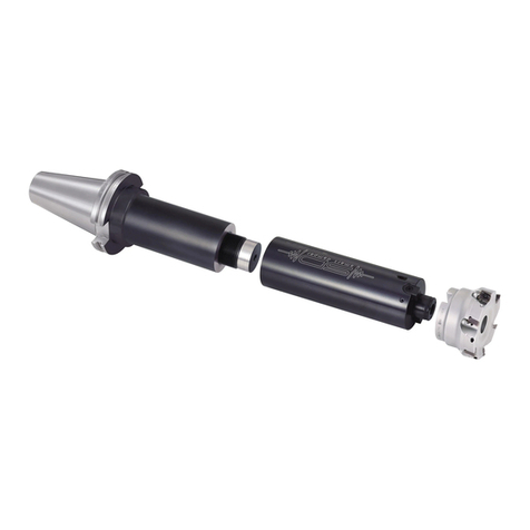
リダクションソケット(CK1・2・3・4・5)
※CK6の場合はスペーサを使用
Reductionsocket
(CK1・2・3・4・5)
※CK6needsaspacer
回転クランプノブ
Rotaryclampknob
ヘッドクランプノブ
Headclampknob
ストッパ
ストッパ
While checking the dial, fix the stopper at the diameter that is φ0.1〜0.2mm
smaller than the target diameter. (Fig.2)
Be ware of the position of the stopper at this time. (Fig.3)
After attaching the cartridge to the head, insert it to the reduction socket
prepared in 1 and clamp the head clamp knob correctly in CK setting hole of
the head. (Fig.1)
After making the insert contact with the probe, turn the reduction socket and
tighten the rotary clamp knob at a point where the pointer of the dial gauge is
at the highest point.
(With this operation, the dial gauge and the cutting edge are set at correct
position.)
Refer to the instruction manual "ADJUSTING TO BORING DIAMETER"
enclosed in the head as to how to adjust the boring diameter of each head.
Insert the reduction socket suitable to the shank size of the head into the
presetter.(Fig.1)
HOW TO PRESET RW HEAD
■EXPORTDEPARTMENT
TEL(+81)-72-982-8277
