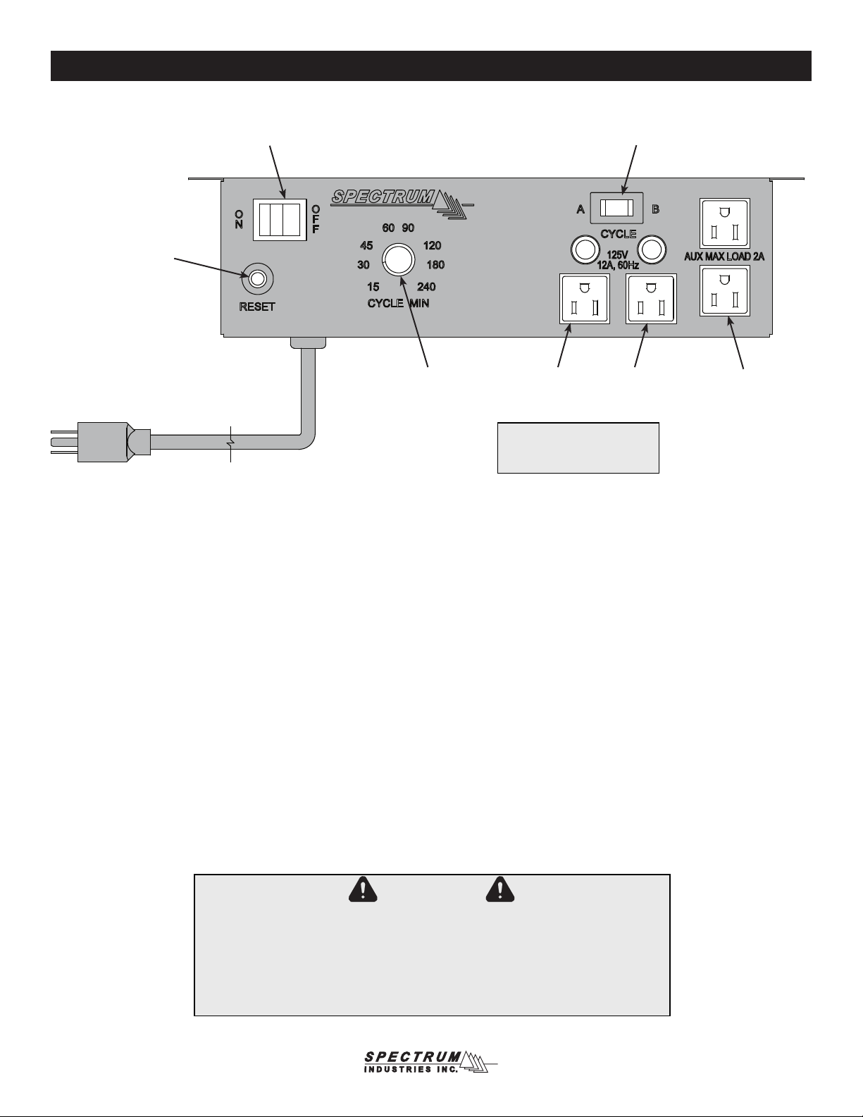
Spectrum Industries 55460 User manual

0113636 Page 1 of 9
CAUTION:
Before using this product, read this manual and follow
all safety and operating instructions.
Before you begin, please make sure all parts and
proper quantities are included. Any parts damaged
during shipment must be reported within 15 days of
receipt. To report information regarding damages or if
you have any questions, please call 1-800-235-1262.
To purchase parts or accessories, please contact us at
www.spectrumfurniture.com
1-800-235-1262
Thank you for purchasing Spectrum products!
Spectrum Industries, Inc
Chippewa Falls, WI 54729, USA
Owner’s Manual
Ultrabook Cart
55460

0113636 Page 2 of 9
Safety
Hardware Package Contents
Assembly / Setup
• Read this owner’s manual before assembly or operation.
• Do not allow children to move cart.
• Move slowly and carefully when mobile.
• For indoor use only. Do not install or store the unit where it will be exposed to weather. Keep unit dry.
• For added safety, plug the unit into a grounded three-prong receptacle controlled by a GFI
• (Ground Fault Interrupter) circuit breaker.
Tools Required
7/16” or adjustable wrench 4mm hex wrench
(included)
(4) 052605
1/4-20 x 15mm JC bolts
(1) 025039
4mm hex wrench
1. Handle Assembly
A. Determine which side of the cart the handle is to be mounted.
B. Attach the handle to the cart with (4) 1/4-20 x 15mm JC bolts and tighten securely. Figure 1.
Figure 1
Handle1/4-20 x 15mm JC bolts
(4 req’d)
Note: Attaching the handle on the same side of the cart as the
2 swivel balloon wheels will provide more control when the
directional wheels are locked.

2. Ultrabook Wiring
A. Open the Student-Side doors.
B. Place up to 32 Ultrabooks or Macbook Airs®into the cart. Figure 2A.
C. Leave doors open.
student-side view
(shown with doors removed)
cord management holes Ultrabook
0113636 Page 3 of 9
Figure 2A

Ultrabook Cart
section view
Ultrabook
Ultrabook
cord
management
trays
16-outlet
power unit
charge cord
charge cord
0113636 Page 4 of 9
Figure 2B
D. Route each charge cord over each Ultrabook as shown and through the cord management holes. Figure 2B.
E. Plug each Ultrabook charger into one of the 16-outlet power strips and plug in other end to Ultrabook.
F. If necessary, bundle excess charger cords and store in the cord management trays.

16-outlet
power unit
instructor-side view
(shown with doors removed)
15’ retractable
cord reel (15-amp)
42” power cords
(connect to A & B
outlets cycle timer)
16-outlet
power unit
cord management trays
cycle timer
0113636 Page 5 of 9
Figure 3
3. Cart Wiring

Value Cycle Timer Operation
Using Timer
The timer prevents overload by alternating power between both power strips in the cart, providing charging to multiple laptops during the day. The power
strips plug into the outlets labeled ‘A’ or ‘B’.
The timer control can be adjusted between 15-240 minutes. This is the number of minutes a power strip will be “hot” before the timer switches to the
other power strip. 15 minutes can be used as the default setting, but the time setting will depend on the laptop size, battery capacity, frequency of laptop
use, and the time available for charging between uses. Lower minute settings should be used if the laptops are being used more frequently.
• To cycle charge both ‘A’ and ‘B’ sides, keep the cycle switch in the middle ‘Cycle’ position, then set the timer control to the desired cycling increment.
After the Side ‘A’ time expires, the timer will activate Side “B” for the same period of time and will continue to cycle until the On/Off switch is set to the
“OFF” position.
• To manually-override the timer function, and charge side ‘A’ only, switch the cycle switch from the middle to the ‘A’ position.
• To manually-override the timer function, and charge side ‘B’ only, switch the cycle switch from the middle to the ‘B’ position.
Specications
• 15-amp, 120 volt, 60Hz
• 15-240 minute timer
• 14 AWG power cord
CAUTION
• Do not use the auxiliary outlets to charge multiple laptops (use the ‘A’ and ‘B’ outlets only.)
Auxiliary outlets are for peripheral use only.
• Total equipment load not to exceed 12-amps per power strip.
• For indoor use only. Do not install or store the unit where it will be exposed to weather.
Keep unit dry.
• For added safety, plug the timer into a grounded three-prong receptacle controlled by a
GFI(Ground Fault Interrupter) circuit breaker.
Cycle Switch
On / Off Switch
(Controls power to timer
‘A’ & ‘B’ outlets)
15-amp Reset Button
Auxiliary
(constant-power)
2-outlets used for
accessories such as
Wi-Fi routers, teacher
laptops, or printers
Right (B) power
unit outlet &
indicator
Left (A) power
unit outlet &
indicator
Timer
Control
Power Cord
Note: Each cart power unit
needs to be plugged into a
separate outlet (‘A’ or ‘B’).
0113636 Page 6 of 9

0113636 Page 7 of 9
Cord reel operation
Operating Instructions:
1. To latch cord - Pull cord out to full length. Allow the cord to retract 1-2 feet back into
the reel. Pull the cord out slowly. When a ‘click’ is heard, the cord will latch in place.
2. Plug into 110-125V (single phase), 3-conductor wall outlet.
3. To release cord - Unplug from wall outlet. Pull cord out slowly until clicking stops.
The latch will release and the cord can be guided back into the reel. Do not allow the
cordtoyunrestrictedbackintothereel.
4. Do not overload or circuit breaker (15-amp maximum) will cut off current. To restore
power, remove overload, wait two minutes, then reset the circuit breaker by pressing
the button on the back of the 3-prong male power plug.
Maintenance:
1. Remove dirt and grime as soon as it accumulates on the reel case by using a soft,
damp cloth (a mild detergent may be used if needed), being careful not to wet
the electrical plug. Never immerse any part of the unit in any solution to clean.
DO NOT use solvents such as gasoline, turpentine, etc. to clean unit.
2. Keep cord clean to assure smoothest automatic retraction. Simply pull cord to its
full length and allow to retract through a dampened rag. Pull out full length again
and sprinkle cord with talcum powder.
Specications:
15’ retractable, 15-amp, 125V, 12 AWG with breaker, UL listed
WARNING
• This cord reel is intended for general indoor use only. It is not intended to be used
inpotentiallydangerouslocationssuchasammableorexplosiveatmospheres.
The reel is not waterproof and not intended for use in potentially wet locations.
• Do not overload (15-amp maximum).
reset button
power plug
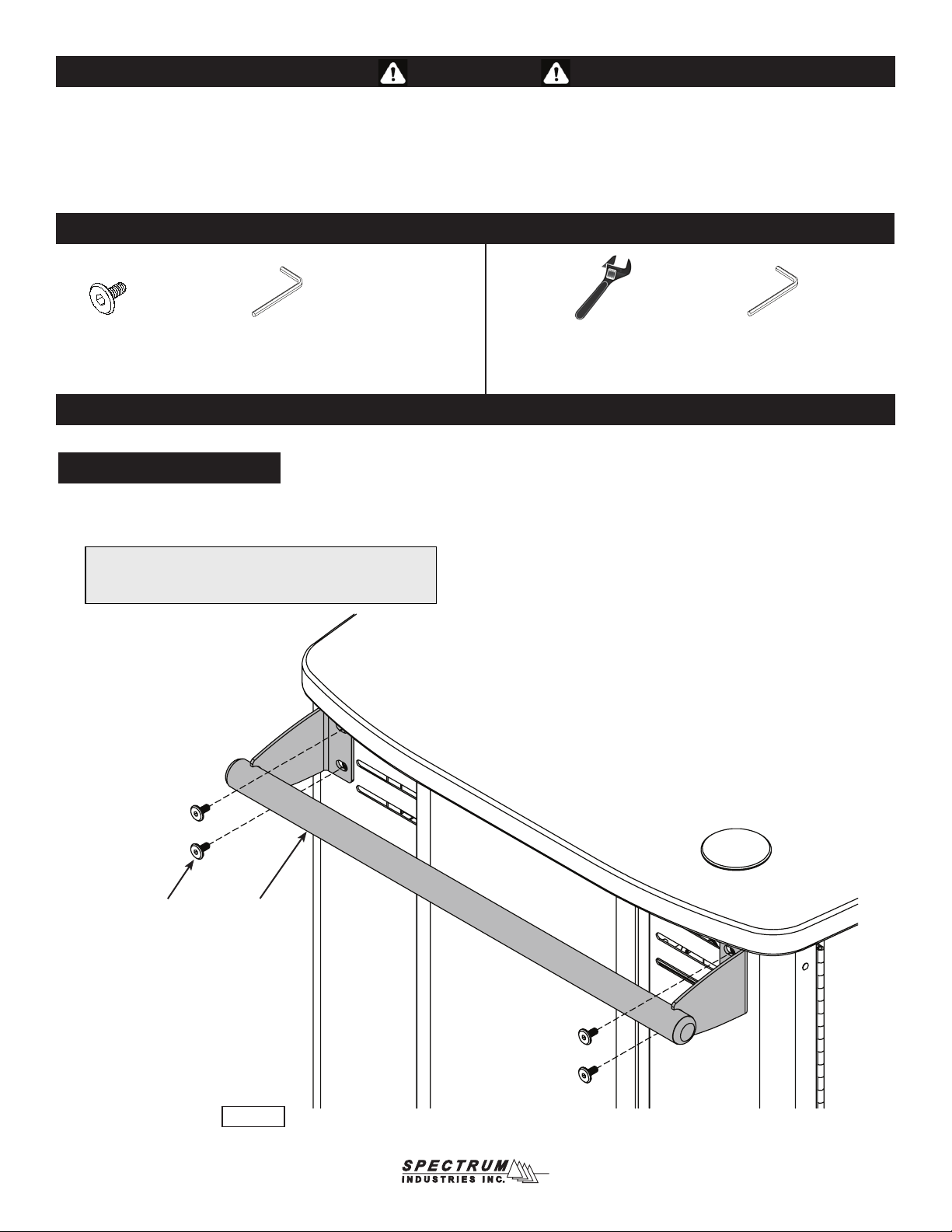
Divider Panel Removal
The divider panels can be removed or recongured to accept a wide variety of
tablets and devices.
A. To adjust or remove the dividers, use a Phillips screwdriver to remove the
(4) 8-32 x 1/2” PHM screws securing the divider stop bracket. Figure 4.
B. Adjust / remove the dividers as necessary.
C. Replace the bracket and PHM screws. Tighten screws securely.
Figure 4
divider stop
bracket
Figure 6
Wheel Operation
Two directional, swivel locking 5” directional balloon wheels are provided and can be rotated
and locked at 180° intervals to be rigid, or unlocked to be swivel. This provides control when
transporting between classrooms, while allowing maneuverability in tight spaces.
Figure 5
Door Stop Adjustment
If necessary, the offset door stop can be rotated slightly to adjust
the closed position of the doors and lock rods.
1. To rotate, loosen the JC bolt slightly with a 4mm hex wrench. Figure 6.
2. Rotate the door stop until the door is positioned correctly.
3. Re-tighten the JC bolt securely.
A. To lock the wheel direction, align each wheel with the cart width and depress
the brake lever. Figure 5. (Each wheel can be locked at 180° intervals)
B. To resume swivel operation, unlock each brake lever.
brake lever
Note: Wheel rotation cannot be locked on
directional wheels. To prevent the cart
from rolling, lock the standard locking bal-
loon wheels on the other side of the cart.

0113636 Page 8 of 9
Options
Replacement Key Set
55142
Pull-out Instructor Shelf
(for instructor laptop or storage)
257⁄16”W x 113⁄8”D x 313⁄16”H
55442
Additional Steel Handle
(mounts on left or right-max 2 per unit)
203⁄16”W
55393
Moving the cart
1. Before moving the unit, unplug all power cords and retract the power cord into the reel.
2. Be sure the casters are in the unlocked position and the doors closed.
3. Move the cart slowly and carefully.
4. Lock the casters after moving.

925 First Avenue, PO Box 400, Chippewa Falls, WI 54729 Ph: 1-800-235-1262 Fax: 1-800-335-0473
0113636 Page 9 of 9
Warranty
WE WILL MAKE IT RIGHT FOR YOU!
Spectrum is committed to provide complete customer satisfaction. Each of our products are manufactured from the best materials available and each
product is stringently monitored throughout the production process through our P.A.C.E. program (Product Assurance to meet Customer Expectations).
Our Customer Service Help Line 1-800-235-1262 is ready to provide immediate attention to any questions, comments or concerns. We are available
to answer your calls Monday through Friday from 7 am to 5 pm CST, excluding observed holidays. In addition your product comments or concerns are
Warranty Statement
We guarantee all Spectrum products to be free of all defects in materials and workmanship, for the original owner, for a period of ten years. Any item
deemed defective by Spectrum or the original manufacturer, under normal use conditions, will be repaired or replaced at Spectrum’s discretion. This
warranty applies to all products manufactured and distributed by Spectrum except the products
listed below.
Items that have a varying warranty include, but are not limited to, the following:
• Adjustable Crank/Electric Desk Legs (1 yr)
• Flat Panel Desk Gas Cylinders (1 yr)
• Upholstered Soft-Goods (5 yrs)
• Adjustable Height & Stacking Chair Parts – including frames, gas cylinders, wood and plastic parts, and control handles (7 yrs)
• Adjustable Height & Stacking Chair Casters (2 yrs)
• Chair Upholstery & Textiles (2 yrs of normal use of Soft Goods, Adjustable Height, Stacking, Wood and Metal Chairs)
• Chair Upholstery - Graded-In Fabrics and C.O.M (no warranty)
• Height Adjustable Columns and Lifts (1 yr)
• General Use Casters (1 yr)
• Electrical – Electri-Pak, Power Communication Modules, and special order ECA electrical items (1 yr)
• Electrical - Power Strips & Electrical Timers (1 yr)
• Electrical Surge Suppressors (lifetime)
• Electrical - Retractable Power Cords (1 yr)
• Keyboard/Mouse Trays (1 yr)
• Flat Panel Monitor Arm – General Parts (5 yrs)
• Flat Panel Monitor Arm – Gas Cylinders (2 yrs)
• CRT Monitor Arm (1 yr)
Warranty is void if product is not used for its intended purpose or subjected to an unusual application, multiple-shift use, alteration, accident, abuse or
abnormal wear and tear. Representations of colors on-line and in printed materials are meant to be a close reference to the actual colors but not an
exact match. Slight variations in color and texture of wood stains, powder coating, laminates, fabrics and other materials are normal in different manu-
facturing lots; as such these variations are not considered defects.
DESIGNED FOR INDOOR USE ONLY – Unless specifically stated in the product specifications, Spectrum’s products have been designed and con-
structed for indoor use only. Moving or using outdoors, or on excessively rough surfaces, may cause damage to the products and will void the warranty.
If an outdoor application is desired please contact us to discuss potential custom design solutions.
The warranty, as stated above, supersedes any previous warranties and is effective as of 9/1/2010
Table of contents
Other Spectrum Industries Batteries Charger manuals