SpeedEPart CHIP-N-VAC 552496 User manual
OWNERS
MANUAL
Model No.
552496
Includes Deck
Adapter #62468
PRINTED IN U.S.A. FORM NO 28104 (03/31/16)
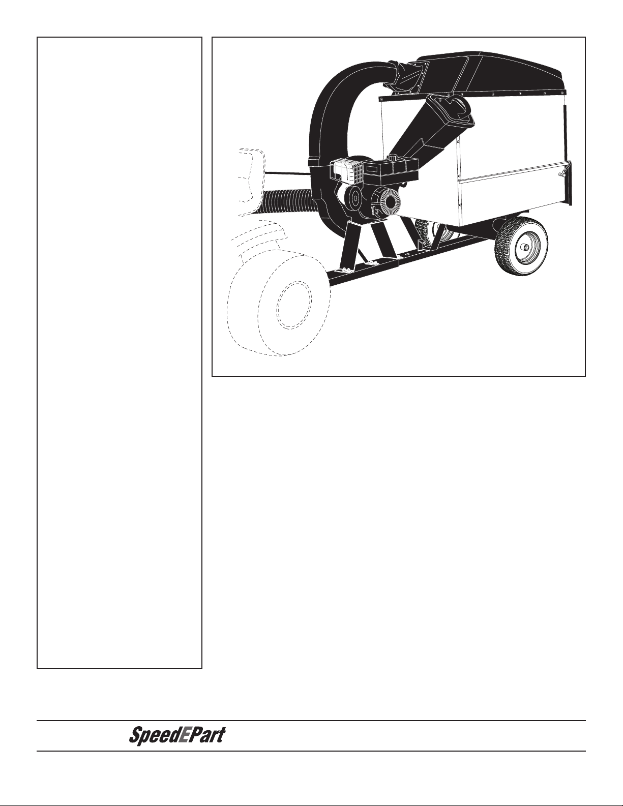
CHIP-N-VAC
Call 1-800-448-9282 for missing parts or assembly help.
the fastest way to purchase parts
www.speedepart.com
IMPORTANT: The engine is shipped without oil. Add oil
before starting the engine.
IMPORTANT: The wheel bearings are not prelubricated.
Fill the wheel hubs with grease after assembling the wheels
to the axle.
CAUTION:
Read Rules for
Safe Operation
and Instructions
Carefully
IMPORTANT: Hose extension kit #65640 may be
required for rear engine tractors and zero turn tractors.

2
TABLE OF CONTENTS
SAFETY RULES.......................................................3,4
FULL SIZE HARDWARE CHART........................... 5,10
CARTON CONTENTS .................................................6
ASSEMBLY.................................................................. 7
OPERATION.............................................................. 12
MAINTENANCE ........................................................ 14
SERVICE AND ADJUSTMENTS ............................... 15
STORAGE ................................................................. 15
TROUBLESHOOTING............................................... 16
REPAIR PARTS ILLUSTRATIONS ..................17,18,20
REPAIR PARTS LISTS .....................................17,19,20
SLOPE GUIDE ..........................................................21
OPTIONAL ACCESSORY
MODEL NO. 45-0253
12 FT. REMOTE HOSE KIT
The Remote Hose Kit, Model 45-0253, provides
12' x 5" diameter hose to clean around shrubs,
patios, window wells and other areas not
accessible to the tractor.

3
SAFETY
Any power equipment can cause injury if operated improperly or if the user does not understand how to operate the equipment. Exercise
caution at all times, when using power equipment.
• Readandfollowallinstructionsinthismanualbeforeattempting
to assemble or operate this equipment. Failure to comply
with these instructions may result in personal injury. Keep this
manual in a safe place for future reference and for ordering
replacement parts.
• Readthisoperatingandserviceinstructionmanualcarefully.
Be thoroughly familiar with the controls and proper use of this
power vacuum.
• Readthevehicleownersmanualandvehiclesafeoperation
rules before using this equipment.
• Never allow children under 16 to operate this Chip-N-Vac.
Children 16 years and older should only operate under close
parental supervision.
• Donotallowanyonetooperatethisequipmentwithoutproper
instructions.
• Donotallowpassengerstorideonthisequipmentoronthe
towing vehicle.
• Keeptheareaofoperationclearofallpersons,particularly
small children. Also keep area clear of pets.
• Checkfuelbeforestartingengine.Donotllfueltankindoors,
or when engine is running, or while engine is hot. Wipe off any
spilled fuel before starting engine.
• Engineandmufflergethot.Donottouch!Toavoidrehazard,
keep clean of debris and other accumulations.
• NeverstoreChip-N-Vacwithfuelintank.Allowenginetocool
before storing in any enclosure.
• Donotchangeenginegovernorsettings.
• Do not operate engine if air cleaner or cover is removed,
except for adjustment. Removal of these parts could create a
rehazard.
• Keephands,feet,face,longhairandclothingoutofinletand
discharge area. There are ROTATING BLADES inside these
openings.
• Beforecleaning,repairingorinspecting,makecertainallmoving
parts come to a complete stop.Disconnect spark plug wire and
keep wire away from plug to prevent accidental starting. Keep
throttle control lever in stop position.
• IftheChip-N-Vacshouldbecomeblockedwithdebrisatany
point, shut engine off and wait until the impeller comes to a
complete stop before attempting to remove the obstruction.
Disconnect spark plug wire to prevent accidental starting.
• If the cutting mechanism strikes a foreign object, or if your
Chip-N-Vac should start to vibrate abnormally, stop the engine
immediately, disconnect the spark plug wire and move the wire
away from the spark plug. Allow the machine to stop and take
the following steps.
a. Inspect for damage.
b. Repair or replace any damaged parts.
c. Check for loose parts and tighten to assure
continued safe operation.
• Checkallboltsfortightnessatfrequentintervalstohelpinsure
safe operation.
• Checkvinylhardtopbootfrequentlyforwear.Replaceifworn
or damaged.
• NeveroperateChip-N-Vacunlessdeckadapter,hose,hose
adapter (nozzle), discharge chute (elbow), and top cover are
properly attached in their place.
• Donotremovetopcoverorattempttoemptycontentsofcart
while engine is running.
• Neverattempttochangehoseadapter(nozzle)ortoinstall
remote hose attachment when engine is running.
• Keepallshieldsandguards(e.g.dischargechute(elbow)and
hose adapter (nozzle) in place and securely attached.
• Alwayswearsafetyglassesorothersuitableeyeprotection
when operating or maintaining this equipment.
• Do not stand behind cart in exhaust discharge area while
engine is running.
• Donotoperatethisequipmentwhileintoxicatedorwhiletaking
drugs or medication that impairs the senses and reactions.
• Whenusingthisequipment,startwiththevehicletransmission
inrst(low)gearandthengraduallyincreasespeedonlyas
conditions permit.
• Operatethisequipmentatreducedspeedonroughterrain,
along creeks and ditches and on slopes to prevent tipping or
loss of control. Do not drive too close to a creek or ditch.
• Vehicle brakingandstability areaffectedby the additionof
thisequipment.DonotlltheChip-N-Vactoitsfullcapacity
without checking the capability of the towing vehicle to safely
pull and stop with the Chip-N-Vac attached.
• Beforeoperatingonanygrade(hill)refertothesafetyrules
in the vehicle owner's manual concerning safe operation on
slopes. Also refer to the SLOPE GUIDE on page 21 of this
owner's manual. Do not operate on slopes in excess of 10
degrees. STAY OFF STEEP SLOPES.
• Followthemaintenanceinstructionsoutlinedinthismanual.
Look for this symbol to point out important safety precautions. It means — Attention!! Become alert!!Your safety
is involved.
DANGER: This Chip-N-Vac was built to be operated according to the rules for safe operation in this
manual. As with any type of power equipment, carelessness or error on the part of the operator can
resultinseriousinjury.Thisunitiscapableofamputatingngersandhandsandthrowingobjects.
Failure to observe the following safety instructions could result in serious injury or death.

4
WARNING
• ReadOwner'sManualandallsafetylabelsonmachinebeforestartingandusingmachine.
• DoNotremovetopcoverorattempttoemptycontentsofcartwhileengineisrunning.
• DoNotstandbehindcartinexhaustdischargeareawhileengineisrunning.
• Keephands,feet,face,longhairandclothingoutofchipperinlet,vacinlet,anddischarge
area.ThereareROTATINGBLADESinsidetheseopenings.
• Wearapprovedsafetyglassesandgloves.Avoidloosettingclothes.
• Keeptheareaofoperationclearofallpersons,particularlysmallchildrenandpets.
• Keepallshieldsandguards(e.g.upperchipperchuteextension,dischargechute,nozzle
assembly)inplaceandsecurelyattached.
• Checkdischargebootfrequentlyforwear.Replaceifwornordamaged.
• Ifunitbecomescloggedorjammed,shutoffenginerightaway.DoNotattempttoclear
clogorjamwithenginerunning.
• Mufflerandenginegethotandcancauseburns.DoNotTouch.Toavoidarehazard,
keepleaves,grassandothercombustibledebrisoffhotmufflerandengine.
• DoNotattempttoremoveorattachvacnozzleoroptionalHoseKitwithenginerunning.
• DoNotoperateunitunlessnozzleoroptionalHoseKitissecuredinplace.
• DoNotllgastankwhileengineisrunning.Allowenginetocoolatleast2minutes
beforerefueling.
HAZARDOUS ROTATING BLADES INSIDE. KEEP HANDS AWAY FROM ALL
OPENINGS.DONOTREMOVEORATTACHHOSE,HOSEADAPTER,ELBOWOR
OPTIONAL HOSE KIT WHEN ENGINE IS RUNNING!
DANGER
WARNING
This unit is equipped with an internal combustion engine and should not be used on or near unimproved forest-covered, or
grass-covered land unless the engine's exhaust system is equipped with a spark arrester meeting applicable local or state
laws (if any). If a spark arrester is used, it should be maintained in effective working order by the operator.
In the State of California the above is required by law (Section 4442 of the California Public Resources Code). Other
states may have similar laws. Federal laws apply on federal lands. A spark arrester muffler is available at your nearest
engine authorized service center.
WARNING
MUFFLER & ADJACENT AREAS
MAY EXCEED 150 F
ROTATING CUTTING BLADES.
KEEP HANDS AND FEET OUT
OF OPENINGS WHILE MACHINE
IS RUNNING.
DANGER
TO AVOID SERIOUS INJURY

5
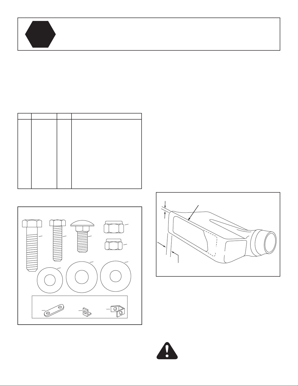
HARDWARE PACKAGE CONTENTS
Seepage10fortheDeckAdapterhardwarepackage.(Contentsnotincludedhere.)
REF. PART
NO.
QTY DESCRIPTION
A 46938 4 Bolt, Hex 3/8" x 3-1/4"
B 43087 6 Bolt, Hex 3/8" x 1-1/4"
C 1509-90 3 Bolt, Hex 1/4" x 1-1/4"
D 47630 4 Bolt, Hex 5/16" x 3/4" (ST)
E 1543-69 4 Washer, Nylon
F 43081 19 Washer, Flat 5/16"
G 43601 4 Washer, Flat 1"
H 43003 4 Lock Washer, 3/8"
I HA21362 6 Nylock Hex Nut, 3/8"
REF. PART
NO.
QTY DESCRIPTION
J 47810 3 Nylock Hex Nut, 5/16"
K 43343 1 Pin, Hair Cotter 1/8"
L 43093 2 Pin, Cotter 1/8" x 1-1/2"
M 44678 2 Spacer Tube
N 49932 1 Hitch Pin
O 43790 1 Tarp Strap, 25"
P 44850 2 Tarp Strap (Less Hooks)
Q 44849 2 "S" Hooks
R 42749 1 S" Hook (Large)
G
D
C
B
A
HI
KL
J
SHOWN FULL SIZE
F
NOT SHOWN FULL SIZE
MNP
O
E
R
Q
6
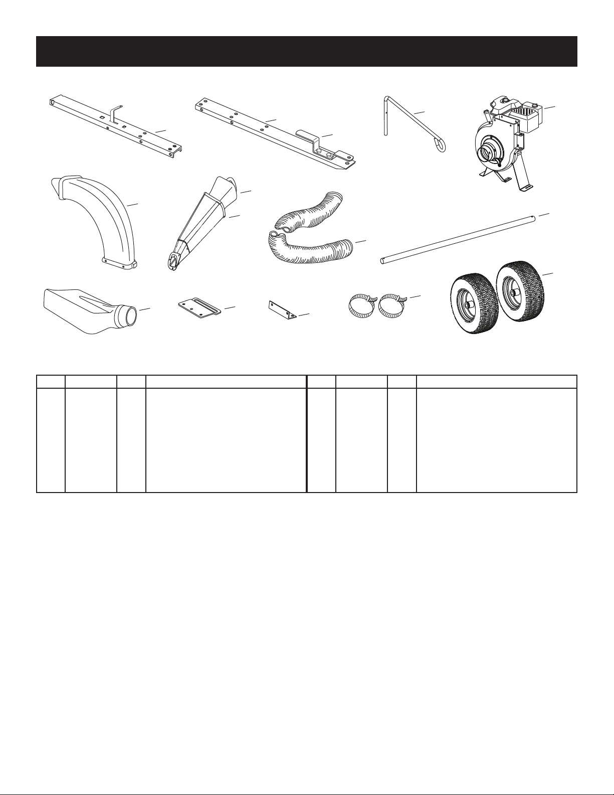
REF. PART NO. QTY. DESCRIPTION
1 ----- 1 Rear Tongue w/Latch
2 27863 1 Front Tongue
3 27264 1 Hitch Bracket
4 49974 1 Hose Hanger Rod
5 ----- 1 Engine/Base Assembly
6 46420 1 Elbow
7 ----- 1 Chipper Chute Assembly
8 731-1617 1 Tamper Plug
REF. PART NO. QTY. DESCRIPTION
9 41882 1 Hose
10 24897 1 Axle
11 43830 1 Deck Adapter
12 23560 1 Adapter Bracket
13 27304 1 Attachment Bracket
14 43793 2 Hose Clamp
15 42159 2 Wheels
10
1
24
3
15
11
5
6
8
9
7
12 13
14
CARTON CONTENTS
7
ASSEMBLY
This unit is shipped WITHOUT GASOLINE or OIL. After
assembly, see separate engine manual for proper fuel
and engine oil recommendations.
TOOLS REQUIRED FOR ASSEMBLY
(1) Pliers
(2) 7/16" Wrenches
(2) 1/2" Wrench
(2) 9/16" Wrenches
FIGURE 2
REMOVAL OF PARTS FROM CARTONS
1. Remove the hardware packs and all loose parts from
the cartons.
2. Lay out and identify parts shown in carton contents.
3. Lay out and identify parts in the hardware packs. Keep
contents of each hardware package separate.
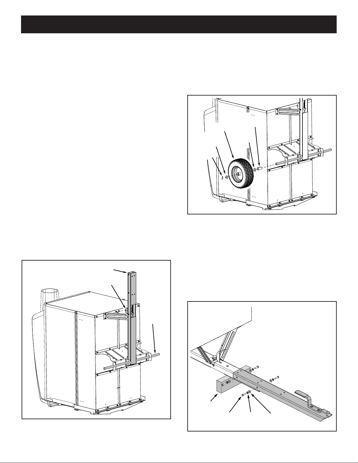
FIGURE 1
ASSEMBLING THE CHIP-N-VAC
1. Tip the cart back to rest upright on the rear of the cart.
Seegure1.
2. Install the rear tongue and the axle onto the cart body,
sliding the axle through the wheel support and the
tongue. Lock the tongue to the latch stand bracket
withthelatchlocklever.Seegure1.
IMPORTANT: Make sure the tongue is securely locked
to the latch stand bracket by the latch lock lever.
AXLE
REAR TONGUE
LATCH LOCK LEVER
3. Assemble a spacer tube, a 1" at washer, a wheel
(valve stem facing out), and another 1" at washer
ontotheaxleasshowningure2.Securethewheel
with a cotter pin, spreading the ends of the pin.
Repeat on other end of axle.
4. Pumpgreaseintogreasettingsonwheelsuntil
grease is forced out through ends of hubs.
COTTER
PIN
WHEEL
1" FLAT
WASHER
1" FLAT
WASHER
SPACER
TUBE
FIGURE 3
5. Tip the cart forward so that it rests on its wheels.
6. Assemble the front tongue on top of the rear tongue
using four 3/8" x 1-1/4" hex bolts, 3/8" lock washers
and5/16"atwashers.Seegure3.
HINT: For easier assembly, support the rear tongue with
a block of wood.
BLOCK
3/8" x 1-1/4"
HEX BOLT
3/8" LOCK
WASHER
5/16" FLAT
WASHER
8
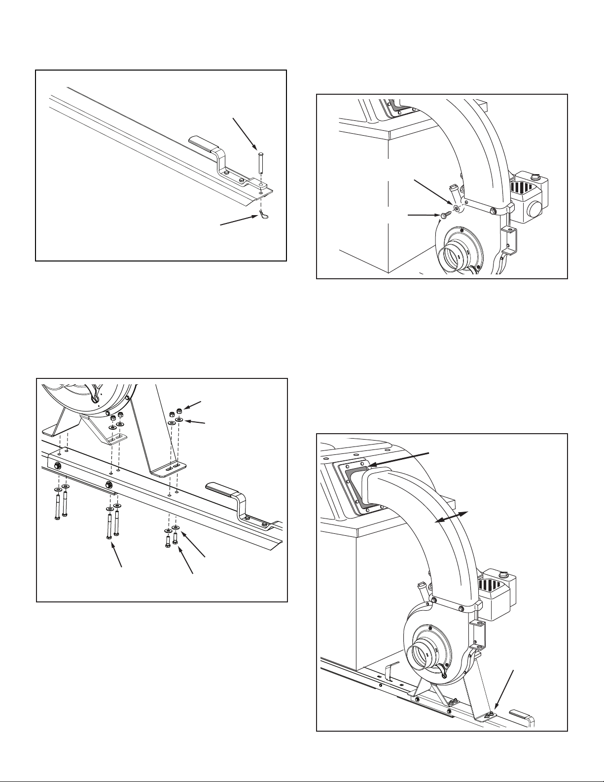
7. Secure the hitch pin to the hitch bracket and tongue
withthehaircotterpin.Seegure4.
FIGURE 4
HITCH
PIN
HAIR
COTTER
PIN
8. Attach the engine base assembly to the tongue using
four 3/8" x 3-1/4" hex bolts, two 3/8" x 1-1/4" hex bolts,
twelve 5/16" at washers and six 3/8" nylock nuts.
Tighten.Seegure5.
FIGURE 5
FIGURE 6
9. Assemble the elbow to the impeller housing using
four 5/16" x 3/4" self tapping hex bolts and four nylon
washers. Push while turning to help start the bolts into
the unthreaded holes. Tighten.Seegure6.
3/8" x 1-1/4"
HEX BOLT
3/8" x 3-1/4"
HEX BOLT
5/16" WASHER
5/16" WASHER
3/8" NYLOCK NUT
5/16" x 3/4"
HEX BOLT
(Thread Forming)
NYLON
WASHER
11. To align the elbow with the opening in the hard top:
a. Push the vinyl boot back inside the opening.
b. Loosen by approximately 1/2 turn each, the six
bolts that you assembled that fasten the engine
basetothetongue.Seegure7.
c. Slide the engine base assembly sideways until the
elbow is aligned with the opening in the hardtop.
d. Retighten the six bolts that you loosened.
12. Pull the vinyl boot onto the end of the elbow.
Loosen (6) bolts
1/2 turn each
Align elbow with opening
FIGURE 7
9
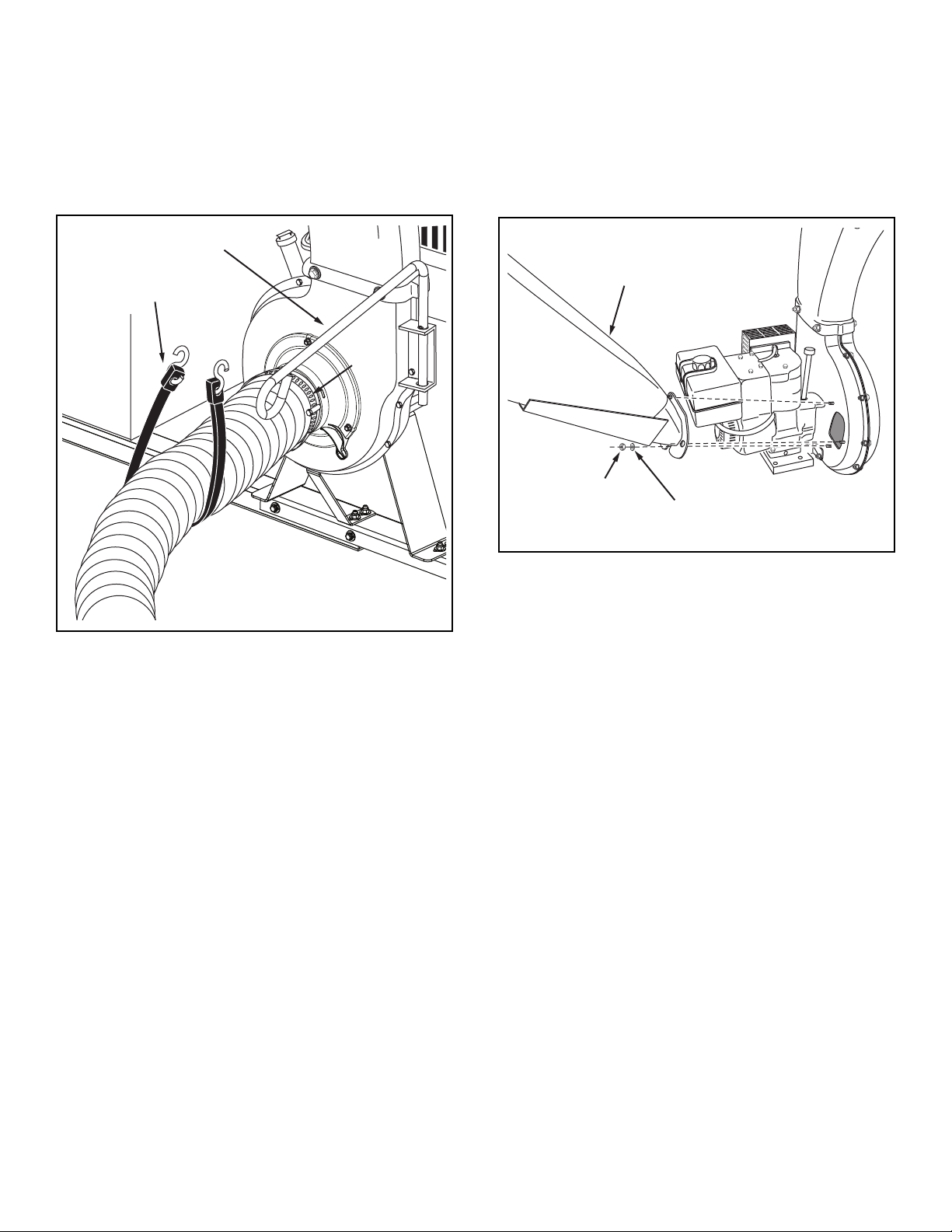
FIGURE 8
14. Place a hose clamp onto one end of hose. Push hose
onto hose adapter (nozzle). Tighten hose clamp onto
hose and hose adapter. Do not collapse hose adapter
whentighteningclamp.Seegure8.
15. Place the hose hanger rod into the hose hanger bracket
ontheimpellerhousingassembly.Seegure8.
16. Loop the 25" tarp strap under the hose. Hook to the
hosehangerrod.Seegure8.
FIGURE 9
HINT: Tip the cart bed back for easier access in the next
paragraph.
17. Attach the chipper chute assembly to the weld bolts
on the back side of the impeller housing using three
5/16" at washers and 5/16" Nylock nuts. Tighten.
Seegure9.
18. Insert the tamper plug into the end of the chipper
chute assembly.
25" TARP
STRAP
HOSE HANGER ROD
HOSE
CLAMP
5/16" FLAT
WASHER
CHIPPER CHUTE
ASSEMBLY
5/16"
NYLOCK
NUT
10
ContentsofHardwarePackforDeckAdapter:
SeeFigure10.
IJK
A B C
E
D
HG
F
NOT SHOWN FULL SIZE
SHOWN FULL SIZE
FIGURE 11
FIGURE 10- FULL SIZE
1/4" DOWN
Keep cut-off as close to
the top edge as possible.
IMPORTANT:
1/2" FROM FRONT
ASSEMBLINGTHEDECKADAPTER(#62468)
TO THE MOWER DECK
NOTE: Not all of the hardware will be used for any one
particulartup.
BEFOREPROCEEDING, lookinthefold-outsheetstondthetemplatefor
your mower deck. If written instructions are printed on the template, follow those
instructions instead of the instructions in this manual.
STOP
CAUTION: Mower deector must be
replaced when Vac System deck adapter
is removed. Do Not operate mower
unless adapter or deector is in place
and properly mounted.
1. Identify and cut out the template for your brandand
size mower deck. If there is no template included for
your deck size, you can make your own template by
marking around a piece of cardboard held against the
edge of the deck's discharge opening.
2. FOLLOW THE INSTRUCTIONS PRINTED ON THE
TEMPLATE. If there are no instructions, use the
following instructions as a general guide.
3. Tape the template to the face of the adapter, about
1/2" from front and 1/4" down from top for deeper
decks. For shallow decks, position template low
enough that adapter will not extend below bottom
of deck. Mark outline of template on face of adapter
using white crayon, nail or scriber. Drill a starting hole
inside the outline, then use a saber saw or key hole
sawtocutouttheopening.Seegure11.
PERFORM THIS STEP ONLY IF NECESSARY.
4. Remove the mower discharge deector from your
mower deck if necessary to attach deck adapter. Save
the deector and hardware for remounting deector.
REF. PART NO. QTY. DESCRIPTION
A 43840 2 Hex Bolt, 5/16" x 1-1/4"
B 43661 4 Hex Bolt, 1/4" x 1"
C 43080 2 Carriage Bolt, 5/16" x 3/4"
D 47810 3 Nylock Nut, 5/16"
E 47189 5 Nylock Nut, 1/4"
F 43088 9 Flat Steel Washer, 1/4" Std.
G 43081 12 Flat Washer, 5/16" Std.
H 1543-69 5 Nylon Washer
I 23825 1 Mounting Strap
J 23826 1 Angle Bracket
K 23827 1 Mounting Bracket

11
FIGURE 12
6. Holding the adapter bracket and the deck adapter
together, position the deck adapter on the mower
deck. Keeping the edge of deck adapter as close as
possible to the offset in the adapter bracket, see if the
slot in the adapter bracket can be aligned with one
or two of the deector holes in your mower deck's
discharge opening. If the bracket can not be located
correctly using existing holes, it will be necessary to
drill one or two 5/16" diameter holes in the deck. See
gure13.
5. Position the adapter over the deck opening, and check
fortofcutoutasshowningure12.Trimcutout,if
necessary,toallowtiltingofadapter,keepingthetas
close as possible for best vacuum suction.
7. Assemble the adapter bracket to the deck using two
5/16" x 1-1/4" hex bolts, 5/16" at washers and 5/16"
nylocknuts.Seegure14.
NOTE: It may be necessary to use extra 5/16" at
washers to shim under the bracket next to the deck
surface. Ten extra washers have been furnished as
shims.Seegure14.
FIGURE 14
FIGURE 15
10. Assemble end of hose and a hose clamp over the
round opening of deck adapter and tighten clamp.
8. With deck adapter positioned correctly over the
discharge opening, use the adapter bracket as a
template and drill three 9/32" diameter holes in the top
ofthedeckadapter.Seegure15.
9. Bolt deck adapter to bracket using three 1/4" x 1"
bolts, nylon washers, 1/4" at washers and 1/4" lock
nuts. Nylon washers should be against the inside of
thedeckadapter.Seegure15.
FIGURE 13
MOWER DECK
DECK ADAPTER
NOTE: Make sure adapter clears gauge
wheels on mower deck
Curl on deck may be located outside of
adapter or inside depending on deck
opening design
DECK ADAPTER MOWER DECK
ADAPTER BRACKET
Keep edge of adapter as close
as possible to offset in bracket
Use existing holes or drill 5/16"
diameter hole or holes.
(3) 1/4" NYLOCK
NUTS
(3) NYLON
WASHERS
(3) 1/4" STEEL WASHERS
(3) 1/4" x 1" HEX BOLTS
ADAPTER
BRACKET
MOWER DECK
DECK ADAPTER
ADAPTER BRACKET
5/16" flat washers
used as needed for
shims to adjust for
variations in decks.
(2) 5/16" NYLOCK NUTS
5/16" x 1-1/4"
HEX BOLT
(2) 5/16" FLAT
WASHERS
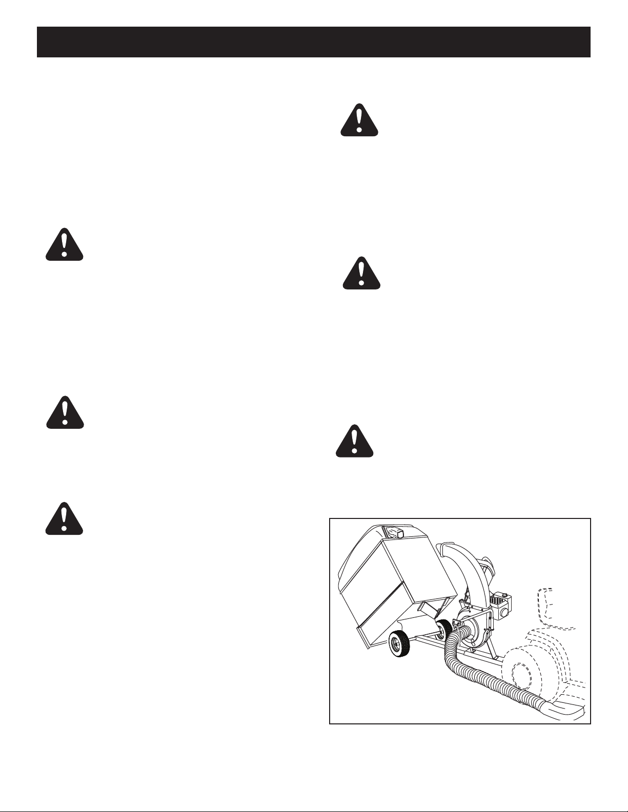
12
FIGURE 16
8. After cart is emptied, secure cart to tongue with latch
and reattach the rear door and the vinyl boot.
HOW TO USE YOUR CHIP-N-VAC
BEFORE STARTING
1. Your Chip-N-Vac engine is shipped without oil or
gasoline. Service the Chip-N-Vac engine with oil and
gas as instructed in the separate engine manual.
2. Inspect the Chip-N-Vac to make sure all covers (rear
door, vinyl boot, elbow, hose adapter, hose and deck
adapter are properly attached.
3. Check tires for proper ination (12 - 14 lbs). Do not
exceed the maximum pressure printed on the side of
the tires.
WARNING: Neverllfueltankindoors,or
with the engine running, or while the engine
ishot.Donotsmokewhilellingtank.
HOW TO STOP YOUR CHIP-N-VAC
1. To stop engine, move the throttle control lever to the
OFF position.
2. Disconnect spark plug wire from plug to prevent ac-
cidental starting while equipment is unattended or is
being worked on.
CAUTION: The muffler and adjacent
areas are hot!
HOW TO START YOUR CHIP-N-VAC
OPERATION
1. Check oil and gas in Chip-N-Vac engine.
2. Attach spark plug wire to spark plug.
3. Move choke lever on engine to CHOKE position.
(A warm engine may not require choking.)
4. Move throttle control lever on engine to FAST position.
5. Grasp starter handle and pull rope out slowly until
engine reaches start of compression cycle (rope will
pull slightly harder at this point). Let the rope rewind
slowly.
6. Pull rope with a rapid, continuous, full arm stroke.
Keeparmgriponstarterhandle.Letroperewind
slowly. Do not let starter handle snap back against
starter.
7. Repeat instructions in two preceding paragraphs until
engineres.Whenenginestarts,movechokecontrol
gradually to RUN position.
WARNING: Never start or run the
engine without all covers being properly
attached to the blower housing and cart.
CAUTION: Vehicle braking and stability
may be affected with the addition of an
accessory or an attachment. Be aware of
changing conditions on slopes.
1. Begin operation at low speed, adjusting forward speed
to match grass height and/or moisture condition to
prevent clogging.
2. Do not attempt to vacuum up any material other
than vegetation found in a normal yard, such as light
branches, leaves, twigs, etc.
3. To empty cart, shut off tractor engine and set brake.
4. Shut off Chip-N-Vac engine.
5. Remove rear door from cart.
6. Release the latch holding cart down to the tongue by
pullinguponthelatchlever.Seegure16.
7. Using a rake or suitable tool, pull the grass clippings
and/or leaves out of cart.
WARNING: Should your Chip-N-Vac
become clogged, shut off tractor and
Chip-N-Vac engines. Before attempting
to unclog, remove wire from spark plug to
prevent accidental starting.
CAUTION: To avoid possible injury, be
sure that no one is near the cart before
releasing the latch.
13
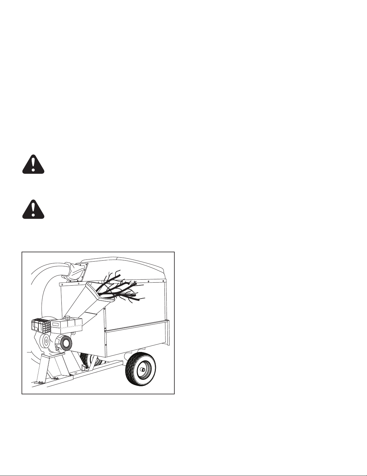
USING THE CHIPPER CHUTE
1. Material such as stalks or heavy branches up to 3" in
diameter may be fed into the chipper chute as shown
ingure17.
2. Be sure to wear eye protection and gloves when
feeding material into the chipper chute.
3. Use the tamper plug, not your hands, to force material
down through the chipper chute.
4. For best performance, it is important to keep the
chipper blades sharp. If the composition of the
material being discharged changes (becomes
stringy, etc.) or if the rate of discharge slows down
considerably, it is likely that the chipper blades are dull
and need to be sharpened or replaced. Refer to the
Service and Adjustments section, on page 15.
WARNING: Do not attempt to feed any
material larger than 3" in diameter into the
chipper chute. Personal injury or damage to
the machine could result.
DANGER:Keephandsout of chipper
chute. Rotating blades in impeller housing
can cause serious injury. Use the tamper
plug to help push material down into the
chute.
FIGURE 17

14
MAINTENANCE
Service Dates
Check for loose fasteners X
Check soft vinyl boot X
Check tire pressure X
Check engine oil level X
Lubricate X
Clean X X
Maintain engine per instructions below and in engine manual.
Before each use
After each use
Every season
Before storage
CUSTOMER RESPONSIBILITIES
• Readandfollowthemaintenancescheduleandthemaintenanceprocedureslistedinthissection.
MAINTENANCE SCHEDULE
Fill in dates as you
complete regular service.
BEFORE EACH USE
CHECK FOR LOOSE FASTENERS
1. Make a thorough visual check of the Chip-N- Vac
for any bolts and nuts which may have loosened.
Retighten any loose bolts and nuts.
CHECK VINYL BOOT
2. Check the soft vinyl boot (on front of hard top) for
wear. Replace if worn or damaged.
CHECK TIRE PRESSURE
3. Check tire pressure regularly. Recommended tire
pressure is 12-14 Lbs. Do not exceed the maximum
pressure listed on the side of the tires.
CHECK ENGINE OIL LEVEL
4. Check oil level before each use. Maintain engine oil as
instructed in the separate engine manual.
LUBRICATION
1. At the beginning of each season, lubricate the latch,
latch pivot bolt, and the axle where the hitch tongue
pivots, with a light machine oil.
2. At least once a season, grease or oil the wheel
bearings. Use automotive wheel bearing type grease
or 20 weight oil.
WARNING: Always stop engine and
disconnect spark plug wire before cleaning,
lubricating or before performing any repairs
or maintenance.
ENGINE MAINTENANCE
1. Check oil level before each use. Maintain engine oil
as instructed in the separate engine manual.
2. Service air cleaner every 25 hours under normal
conditions. Clean every few hours under extremely
dusty conditions. Poor engine performance and
ooding usually indicates that the air cleaner should
be serviced. To service the air cleaner, refer to the
separate engine manual.
3. The sparkplug should be cleaned and the gap
reset once a season. Spark plug replacement is
recommended at the start of each season. Check
the engine manual for correct plug type and gap
specications.
CLEANING
1. Make sure the cart, the side and front panels and
top are cleaned after each use. Grass clippings and
leaves left in the cart will mildew and cause damage if
not cleaned out.
2. Cleantheengine regularly with a cloth or brush.
Keepthecoolingnsontheenginehousingclean
to permit proper air circulation which is essential to
engine performance and life. Be sure to remove all dirt
and debris from muffler area.

15
STORAGE
3. If storing in an unventilated or metal storage shed,
coat metal parts with light oil or silicone to prevent
rust.
4. Store unit in a clean, dry area.
1. Clean the engine and the entire unit thoroughly.
2. Refer to engine manual for correct engine storage
instructions.
SERVICE AND ADJUSTMENTS
FIGURE 18
SHARPENING OR REPLACING CHIPPER
BLADES
1. Disconnect the spark plug wire and move wire away
from the spark plug.
2. Remove the access plate by removing two hex lock
nuts.Seegure18.
3. Locate one of the chipper blades in the access plate
opening by rotating the impeller assembly by hand.
Remove the blade using a 3/16" allen wrench on
the outside of the blade and a 1/2" wrench on the
impeller assembly, inside the housing.
4. Remove the other blade in the same manner.
5. Replace or sharpen blades. If sharpening, make
certain to remove an equal amount from each blade.
Reassemble in reverse order.
NOTE: Make certain the blades are reassembled with
the sharp edge facing upward, as viewed from the access
plate opening.
NYLOCK NUTS
ACCESS
PLATE
REMOVING THE IMPELLER
1. To remove an impeller that is frozen on the shaft,
order the Impeller Service Tool (part #42294) that is
listed on the parts ordering page 20.
2. Remove the bolt that holds the impeller on the shaft
and screw the impeller service tool into the hole until
the impeller breaks free.

16
TROUBLESHOOTING
PROBLEM POSSIBLE CAUSE(S) CORRECTIVE ACTION
Engine fails to start 1. Spark plug wire disconnected. 1. Connect wire to spark plug.
2. Safety switch not contacted. 2. Correctly install hose adapter nozzle.
3. Fuel tank empty, or stale fuel. 3. Fill tank with clean, fresh fuel.
4. Fuel shut-off valve closed 4. Open fuel shut-off valve.
(if so equipped).
5. Faulty spark plug. 5. Clean, adjust gap or replace.
Loss of power; 1. Spark plug wire loose 1. Connect and tighten spark plug wire.
operation erratic. 2. Unit running on CHOKE. 2. Move choke lever to OFF position.
3.Blockedfuellineorstalefuel. 3.Cleanfuelline;lltankwithclean
fresh gasoline.
4. Water or dirt in fuel system. 4. Disconnect fuel line at carburetor to drain
fueltank.Rellwithfreshfuel.
5. Carburetor out of adjustment. 5. Adjust carburetor.*
6. Dirty air cleaner. 6. Service air cleaner.*
Engine overheats 1. Carburetor not adjusted 1. Adjust carburetor.*
properly.
2. Engine oil level low. 2. Fill crankcase with proper oil.
Too much vibration Loose parts or damaged Stop engine immediately and disconnect
impeller. spark plug wire. Tighten all bolts and nuts.
Make all necessary repairs. If vibration
continues, have unit serviced by an
authorized service dealer.
Unit does not 1. Discharge chute (elbow) 1. Stop engine immediately and disconnect
discharge clogged. spark plug wire. Clean inside of housing
and discharge chute (elbow).
2. Foreign object lodged in 2. Stop engine immediately and disconnect
impeller. spark plug wire. Remove lodged object.
3. Chip-N-Vac cart is full. 3. Empty cart.
Rate of discharge Chipper blades dull. Sharpen or replace chipper blades.
when chipping
slows considerably,
or composition of
discharged material
changes.
*Refer to the engine manual packed with your unit.
NOTE: For repairs beyond the minor adjustments listed above, please contact your nearest authorized service dealer.
17
PARTS
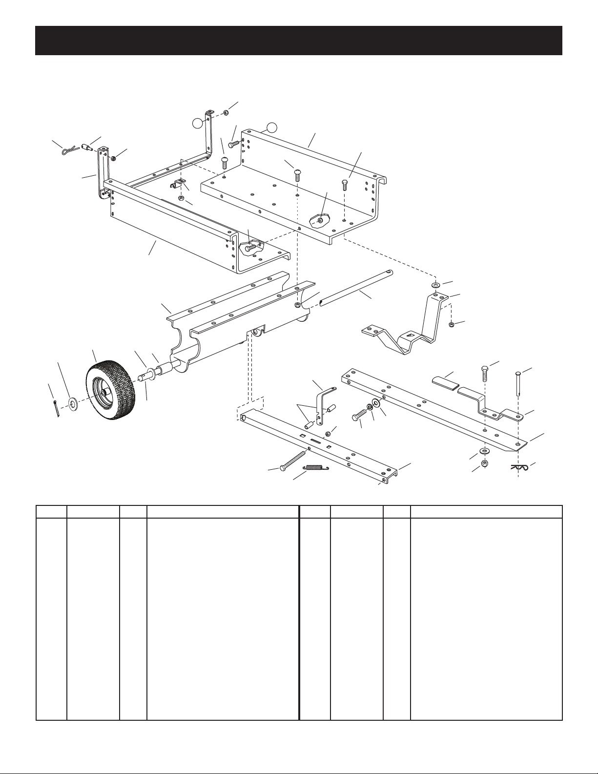
REPAIR PARTS FOR MODEL 552496 CART BODY
11
11
4
1
2
11
1
35
A
5
8
6
8
7
9
12
12
12
12
13
13
10
15
20
23
28 27 A
16
17
18
19
21
22
22
24
25
26
10
10
14
29
31
30 29
REF. PART NO. QTY. DESCRIPTION
1 23985 2 Cart Body
2 62458 1 Tailgate Reinforcement Bracket
3 23507 1 Wheel Support
4 24497 1 Latch Stand Bracket
5 24897 1 Axle, Wheel 1" Dia.
6 42159 2 Wheel w/Tire, 15 x 6.00
7 43093 2 Cotter Pin, 1/8" Dia. x 1-1/2"
8 43601 4 Washer, Flat 1"
9 44678 2 Spacer Tube, 1-1/4" x 2" Lg.
10 47810 13 Hex Nut, 5/16-18 Nylock
11 43866 9 Hex Bolt, 1/4-20 x 5/8"
12 47189 11 Hex Nut, 1/4-20 Nylock
13 43814 13 Truss Hd. Bolt, 5/16-18 x 3/4"
14 41076 2 Spacer
15 43088 2 Washer, Flat 1/4"
16 68346 1 Tongue Weldment Ass'y. (Rear)
REF. PART NO. QTY. DESCRIPTION
17 27863 1 Tongue (Front)
18 24614 1 Latch Lock Lever
19 27264 1 Hitch Bracket
20 49932 1 Clevis Pin, 1/2" x 3"
21 43343 1 Pin, Hair Cotter 1/8"
22 43087 6 Hex Bolt, 3/8-16 x 1-1/4"
23 23838 2 Door Support
24 HA21362 2 Nut, Hex Nylock 3/8-16
25 47407 1 Hex Bolt, 5/16-18 x 4"
26 47408 1 Spring, Extension
27 42999 2 Pin
28 48934 2 Hairpin
29 43081 6 Washer, 5/16"
30 43003 4 Lock Washer, 3/8"
31 47707 1 Grip
18
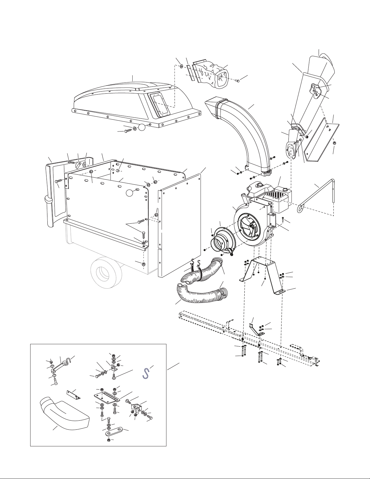
REPAIR PARTS FOR MODEL 552496 CHIP-N-VAC
26
24
25
27
23
439 40
8
12
35
13
21
20
28
33
13
33
35
13
3
6
9
14
16
17
18
29
40
10
11
50
22
20 35
B
B
13
5
8
13
8
13
13
8
40
40
40
40
40
35
35
35
35
44
44
44
34
34
34
47
45
4647
48
37
49
13
51
15
12
12
42
42
52,53,54,55
7
38
35
35
44
8
ADAPTER #62468
31 30
36
35
35
13 57
56
44
1
2
8
32
32
44
44
44
44
43
43 41
19

19
REPAIR PARTS FOR MODEL 552496 CHIP-N-VAC
REF. PART NO. QTY. DESCRIPTION
1 27883 1 Engine Base
2 27882 1 Brace, Housing
3 24958 1 Hose Hanger Bracket
4 43182 2 Bolt, Hex 5/16-18 x 3/4"
5 43840 2 Bolt, Hex 5/16-18 x 1-1/4"
6 43085 4 Bolt, Hex 5/16-18 x 1-1/2"
7 731-1617 1 Tamper, Plug
8 47810 12 Nut, Nylock 5/16-18
9 43791 1 Hose Adapter (Nozzle)
10 47630 4 Screw, Self Tap 5/16-18 x 3/4"
11 49983 3 Hex Nut, Flange Lock 5/16-18
12 43012 19 Bolt, Hex 1/4-20 x 3/4"
13 47189 43 Nut, Nylock 1/4-20 Thd.
14 42462 1 Engine
15 67974 1 Chute Assembly
16 49974 1 Hose Hanger Rod
17 46420 1 Elbow
18 41882 1 Hose (6" x 84")
19 43793 2 Hose Clamp 6"
20 24678 2 Side Panel Cart Extension
21 24679 1 Front Panel Cart Extension
22 23836 1 Cross Brace
23 68606 1 Hard Top Assembly
(Includes 24,25,26,27)
24 42189 4 Rivet, 3/16"
25 43910 2 Washer, Flat 3/16"
26 24798 4 Boot Mounting Strap
27 48133 1 Vinyl Boot (Hardtop)
28 44790 1 Poly Rear Door
29 43790 1 Strap, Tarp 25"
30 44849 2 "S" Hook, #32
REF. PART NO. QTY. DESCRIPTION
31 44850 2 Strap, Tarp (Less Hooks)
32 HA21362 6 Nut, Hex Nylock 3/8-16
33 43866 20 Bolt, Hex 1/4-20 x 5/8"
34 43661 4 Bolt, Hex 1/4-20 x 1"
35 43088 46 Washer, 1/4" STD
36 1509-90 3 Bolt, Hex 1/4-20 x 1-1/4"
37 23827 1 Mounting Bracket
38 24098 1 Bracket, Chute Reinforcement
39 23789 2 Door Latch
40 1543-69 11 Washer, Nylon 21/64"
41 43087 2 Hex Bolt, 3/8-16 x 1-1/4"
42 47598 5 Nut, Hex Flanged Lock 1/4"
43 46938 4 Hex Bolt, 3/8-16 x 3-1/4"
44 43081 27 Washer, 5/16" STD
45 43830 1 Adapter, Deck
46 23560 1 Bracket, Deck Adapter
47 43080 2 Bolt, Carr. 5/16" x 3/4"
48 23825 1 Mounting Strap
49 23826 1 Angle Bracket
50 1 Impeller Housing Assembly
(See page 26)
51 62468 1 Deck Adapter Kit (Includes all
parts in box on page 24)
52 63376 1 Chipper Chute Assembly (Upper)
53 735-0249 1 Flap, Chute (Included in item 52)
54 781-0633 1 Strap, Flap (Included in item 52)
55 728-3001 3 Rivet, Pop 5/32"
56 27304 1 Bracket, Attachment
57 42749 1 "S" Hook, Large
28104 1 Owner's Manual
20
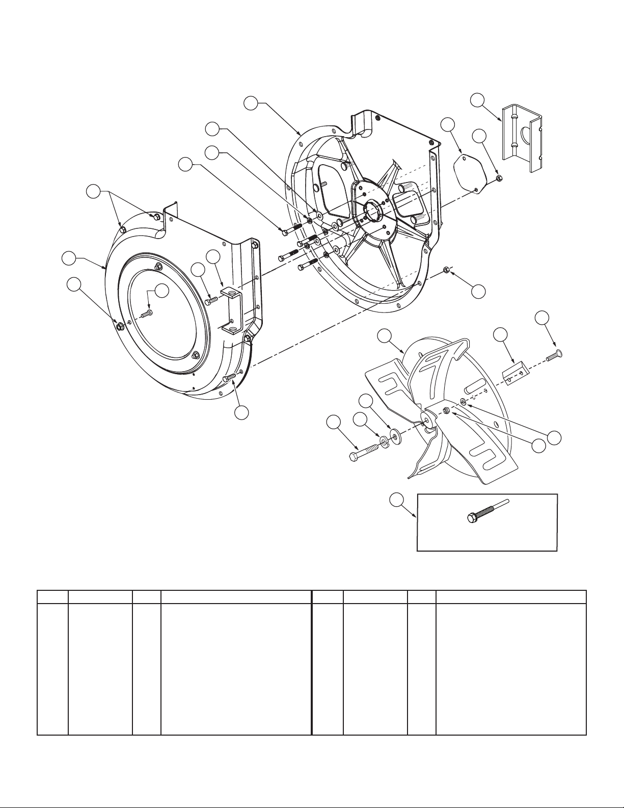
REPAIR PARTS FOR MODEL 552496 CHIP-N-VAC
IMPELLER HOUSING ASSEMBLY
REF. PART NO. QTY. DESCRIPTION
1 24633 1 Housing Ass'y. Outer
2 63993 1 Housing Ass'y. Inner
3 27615 1 Cover, Chipper
4 27187 1 Spacer Bracket
5 24958 1 Hose Hanger Bracket
6 66791 1 Impeller Assembly
7 742-0544B 2 Blade, Chipper
8 47810 14 Nut, Hex Nylock 5/16-18
9 43081 4 Washer, 5/16" STD
10 43086 8 Washer, Lock 5/16" Spring Type
REF. PART NO. QTY. DESCRIPTION
11 710-0772 4 Bolt, Hex 5/16-24 x 2"
12 43182 12 Bolt, Hex 5/16-18 x 3/4"
13 46584 3 Hex Nut, Whizlock 5/16-18 Thd.
14 43063 3 Bolt, Hex 5/16-18 x 1"
15 710-1273 1 Bolt, Hex 3/8-24 x 2-3/4"
16 43003 1 Lockwasher, 3/8"
17 42828 1 Flat Washer, 13/32" x 1-1/4"
18 44738 4 Nut, Hex Lock 5/16-24 "Unitork"
19 710-1054 4 Screw, Flat Hd. 5/16-24 x 1"
20 42294 1 Impeller Service Tool
2
10
2
3
5
8
24
12
1
13 14
5
8
16
15
17
7
19
For removing impeller assembly.
Must be ordered separately.
18
6
10
4
8
20
3
11
12
12
2
9
Table of contents
Other SpeedEPart Spreader manuals


Popular Spreader manuals by other brands

WilTec
WilTec 50133 Operation manual

EINHELL
EINHELL 3415411 Original operating instructions

Trynex International
Trynex International SnowEx Bulk Pro 1875 owner's manual

LEHNER
LEHNER VINERO Operating instructions with parts list

Turf Equipment
Turf Equipment Z-SPRAY JUNIOR Series Operator's manual

SIP
SIP ORION 80 Instruction for work


