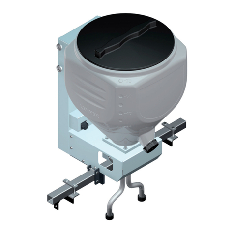
LEHNER VINERO Datasheet

LEHNER
VINERO®
Operating instructions with parts list
Control LAS 3
Software from version 2.0
Status: June 2009
Serial number: .................................................................
Software version: ...............................................................

2
Table of Contents
1 What you should know.......................................................4
1.1 Foreword................................................................................................ 4
1.2 Notes on these operating instructions.................................................... 4
1.3 Intended use .......................................................................................... 5
1.4 Warranty................................................................................................. 5
1.5 About your safety ................................................................................... 6
1.6 Identication........................................................................................... 6
2 Starting up the VINERO®................................................. 7
2.1 Mounting the frame ................................................................................ 7
2.2 Electrical connection .............................................................................. 7
2.3 Mounting the VINERO®........................................................................ 8
2.4 Attaching the control panel .................................................................... 8
3 Operating the VINERO®................................................... 9
3.1 Controls on the control panel ................................................................. 9
3.2 The display........................................................................................... 10
3.3 Switching on / off.................................................................................. 11
3.4 Setting the speed ................................................................................. 13
3.5 Setting the slide opening...................................................................... 13
3.6 Opening/closing the slide..................................................................... 14
3.7 Performing the slide reference run....................................................... 15
3.8 Setting the working width (special accessory) ..................................... 16
3.9 Setting the lateral distribution (special accessory)............................... 16
3.10 Empty signal indicator.......................................................................... 17

3
Table of Contents
4 Settings and displays.......................................................18
4.1 Making settings ..................................................................................... 18
4.2 Language .............................................................................................. 18
4.3 Selecting the empty indicator ................................................................ 19
4.4 Setting signal for electronic lifting gear control (EHR)........................... 19
4.5 Setting cycle for electronic lifting gear control (EHR)
(special equipment for headland manager)........................................... 20
4.6 Adjusting the empty indicator ................................................................ 20
4.7 Displaying the spreader type................................................................. 21
4.8 Checks .................................................................................................. 21
4.9 Spreading width and turning procedure ................................................ 22
5 Special accessories..........................................................23
5.1 Attach standard rail ............................................................................... 23
5.2 Attach Vario rail ..................................................................................... 23
5.3 Headland manager................................................................................ 24
6 Maintenance and cleaning ...............................................26
6.1 Service .................................................................................................. 26
6.2 Cleaning ................................................................................................ 26
7 Appendix ...........................................................................27
7.1 EU Declaration of Conformity................................................................ 27
7.2 Distribution box reference list................................................................ 28
7.3 List of spare parts.................................................................................. 29
7.4 Troubleshooting..................................................................................... 33
7.5 Spreading charts ................................................................................... 34
7.6 Slide settings ......................................................................................... 43

4
1 What you should know
1.1 Foreword
Thank you for placing your trust in us. We congratulate you on your
decision. With the VINERO®, you have acquired a high-quality and
innovative product.
Thanks to its advanced design, meticulous material selection, state-
of-the art manufacturing techniques and the precision work of our
employees,thisequipmentmeetsallefciency,quality,reliabilityand
value requirements.
Care and maintainance in accordance with the operating instructions
ensures safe operation and maintains the value of your VINERO®.
1.2 Notes on these operating instructions
These operating instructions are a part of the VINERO® and must always
be readily available. All persons who work with the VINERO®must read
and follow the operating instructions.
They will learn about the technical details and how to control the
machine and optimise its performance.
Warning notices
Warningnoticesintheseoperatinginstructionsareidentiedasfollows:
Danger!
Warning against immediate danger. Non-observance of
appropriate measures may result in death and severe
personal injury or serious damage to property..
Warning!
Warning of possible danger. Death, severe personal injury
or serious damage to property are possible.
Caution!
Warning of possible dangerous situations. Slight personal
injury or damage to property is possible.

5
1 What you should know
1.3 Intended use
The VINERO®is used exclusively for spreading fertilizer and seeds.
1.4 Warranty
We provide a guarantee of 6 months and warranty of 24 months on the
VINERO®.
Caution!
Defective plugs and cables or those of the wrong size can
leadtofunctionaldeciencies.
Use original or cables and plugs approved by the
manufacturer only.
Any changes to cable or plug connections without factory approval
automatically invalidates the warranty. Motors may not be opened or
dismantled.
Warranty repairs must be coordinated with the manufacturer before any
work is started.
For replacement parts, additional expenses are automatically
charged for any changes made to cables and plugs by the customer.
Replacement parts are to be returned carriage paid.
Rusted bearings are not subject to the manufacturer's warranty.
Prior to assembly:
Check your VINERO®.upon receipt for any damage caused in transit.
Any such damage must be reported to the manufacturer within 24 hours
of receipt.

6
1 What you should know
1.5 About your safety
Carefully read and observe these operating instructions before use.•
Always keep these instructions at the point of use.
Observe the accident prevention regulations, safety and operating•
regulations and the regulations for environmental protection.
Observe all applicable standards and guidelines.•
Whentravellingonpublicroadsandstreets,observetheroadtrafc•
regulations.
Observe the safety instructions.•
Immediatelyresolveanysafety-relateddeciencies.•
Keep out of the spreading zone. Make sure that no other persons are in•
the spreading zone.
Do not touch the hopper during operation.•
Follow the safety guidelines of the package insert when spreading•
granulates.
Do not undertake any repairs, maintenance or cleaning procedures on•
the VINERO®when the mains plug is connected.
1.6 Identication
The serial number of the spreader is located on the back of the
framework.
Note the serial number in these operating instructions so that it is readily
available for inquiries.
The hardware and software versions
arebrieydisplayedwhenthecontrol
panel is connected.
Make a note of the software version in
these operating instructions so that it
is readily available for inquiries.
LEHNER GmbH
LAS3 V2.0

7
2 Starting up the VINERO®
2.1 Mounting the frame
The VINERO® can be screwed on directly or an auxiliary bracket used.
Mounting holes have been provided on the back of the frame.
The recommended delivery height is approx. 0.2 m. Please refer to the
spreading charts for precise details.
The VINERO®can be mounted at the front or back of the tractor. It can
bettedtotractors,all-terrainvehiclesorcultivationmachines.Because
a full hopper makes the VINERO®considerably heavier, the load
capacity of platform gates and other consoles is to be checked.
2.2 Electrical connection
Technical data
Operating voltage 10 to 15 volts
Fuse 25 A
Motor output 12 watts
Speed range 40 to 66 rpm
Power consumption
of gear motor
0.4 - 1 A
Operating temperature -10 to +70 °C
Storage temperature -30 to +70 °C
Any changes to cable or plug connections without factory approval
automatically invalidates the entire warranty. Changes to cables are
taken into account in the case of repair.
You must consult with the manufacture before carrying out any cable
modications.
Power loss must be taken into account when extending cables. A poor
power supply may prevent you from achieving the desired speed. A poor
power supply can momentarily cause the spreader to fail completely.

8
2 Starting up the VINERO®
2.3 Mounting the VINERO®
Checkwhetherthehoppertswellinthehopperplatform.Checkthat
the VINERO® is securely attached.
2.4 Attaching the control panel
Caution, risk of short circuits!
Ensure that the cable is not routed over any sharp edges.
1
2 3 4
Mount support for the control panel in the vehicle cabin.
Plug the control panel cable into the 3-pin plug 1 of the carrier vehicle.
If the plug is not available, use the provided battery cable:
Connect terminal 2to -pin of the battery
(not to the body).
Connect terminal 3(with fuse 4) to +pin of the battery
Place cable end with socket in carrier vehicle.
Plug the spreader cable into the 16-pin plug of the control panel.
The battery cable supplied must be used to ensure an optimum power
supply.
Your device is now ready to operate.

9
3 Operating the VINERO®
3.1 Controls on the control panel
6
1 2 3
54
Switching on / off1
Display2
Opening and closing the slide3
Slide open: green LED lights up
Slide closed: yellow LED lights up
Setting the speed or slide4
Switch to change between speed and slide5
Empty indicator6

10
3 Operating the VINERO®
3.2 The display
Arrow denotes the active line1
Agitator speed2
Slide opening3
OK sign for open slide4
Error messages, also see Troubleshooting chapter.
> RPM 60
Slide 29 ok
1 2
3 4

11
3 Operating the VINERO®
3.3 Switching on / off
Press the button.
The speed of the agitator and the slide
opening is displayed. The slide is always
closed when switching on the drive motor.
> Speed 60
Slide 29
Press the button.
The slide is opened, the green LED lights
up.
The drive motor starts.
> Speed 60
Slide 29 ok
If this message is displayed, a cable is
damaged or a plug disconnected. > Speed 60
Connecting spr.
Low temperatures can cause the empty indicator to respond slowly.
To check the adjustment:
Allow the spreader to run for approx. 1 minute with the slide closed.
If the slide is then opened, the empty indicator must be activated
after approx. 5 seconds.
If this doesn't happen, move the empty indicator 5% into the negative
range; see Settings and displays chapter, Adjusting the empty indicator.

12
3 Operating the VINERO®
Autostart
Ifthemotorisdifculttostartduetoheavy
loads, start the motor up to 10 times in
alternating motor direction. If the mixer
does not break free as a result, the motor is
automatically switched off.
The following message is displayed: Agitator blocked
Slide 29
Danger!
Never open the hopper or touch the spreading disc when
the drive motor is running.
Switch off the drive motor and ensure that the motor is
stopped before opening the hopper or touching the agitator.
To eliminate the blockage:
Switch off the machine.
Empty hopper and check for foreign bodies.
Check power supply.

13
3 Operating the VINERO®
3.4 Setting the speed
If necessary, press the button to select the
speed;thearrowpointstotherstlinein
the display.
> Speed 60
Slide 29
Press the button to set the speed.
The speed can be adjusted continuously
from 40 - 66 rpm.
The optimum speed is 66 rpm.
The setpoint speed is displayed for 10
seconds, after which the actual speed is
displayed.
3.5 Setting the slide opening
If necessary, press the button to select the
slide. The arrow points to the second line
in the display.
Speed 60
> Slide 29
Press the button to adjust the slide
opening.
You can take the required slide opening
from the spreading chart.

14
3 Operating the VINERO®
3.6 Opening/closing the slide
Danger!
The drive motor starts immediately when switched on.
Make sure the danger area is clear when starting.
Press the button to open or close the slide.
Slide open: green LED lights up
Slide closed: yellow LED lights up
> Speed 60
Slide 29 ok
Slide monitoring
Iftheslidedoesnotreachthespeciedpositionwithin10seconds,the
spreader switches off.
The following message is shown in the display:
Slide not open or Slide not closed. 5 warning signals also sound. For
troubleshooting, see Troubleshooting chapter.
Manual adjustment
The number of hoses to be used can be selected by manually setting the
slider. The number depends on the slide; see Slide Settings.
Lever in position Afor all hoses.
Lever in position Bfor some of the hoses.

15
3.7 Performing the slide reference run
The slide motor and control panel are adjusted to match each other
at the factory. The setting can be lost in the course of time or when
replacing the control panel.
Switch off the machine.
Press and hold the button for switching between speed
and slide and the + button to switch the machine on.
The slide performs its reference run.
Approx. 240 is displayed as the upper value and approx. 40 as the lower
value; in the second line the message OK is displayed.
Switch machine off at ON/OFF switch so that the values are stored.
If a slide reference run cannot be performed, the following message
ashesonthedisplay:slide not calib.
Check the mechanical clearance of the slide, the cable and the
connectors. Then perform the reference run again.
3 Operating the VINERO®

16
3.8 Setting the working width (special accessory)
The Vario-rail can be set to a working width of between 0.8 and 1.6 m.
Undo screws (arrowed) and set distributor rails to the desired width.
3.9 Setting the lateral distribution (special accessory)
For wide area output all hoses are positioned vertically on the Vario-rail:
1 2 3 4 5 6 7 8 109 11 12
3 Operating the VINERO®

17
3 Operating the VINERO®
For fertilising rows, the hoses on the Vario-rail are positioned at an
angle. The inner hoses can each be positioned next to an outer hose.
6-hose version:
3-hose version:
3.10 Empty signal indicator
The empty indicator shows you when the spreading material in the
hopperfallsbelowaspeciclllevel:
Thefollowingmessageashesonthedisplayforapprox.5seconds:
Hopperempty,8warningsignalssoundandtheredLEDashesonthe
empty indicator.
To switch off the empty signal:
Close the slide or switch off the spreader.

18
4 Settings and displays
The operating panel can be used to make the following settings:
Language
Empty warning
EHR signal
EHR cycle (special equipment for headland manager)
Empty warning adjustment
Control type
4.1 Making settings
Switch off the machine.
Press both buttons at the same time to
switch on the machine.
The language selection is displayed.
Language 0
English
Press the button to select the desired
menu item.
4.2 Language
Press the button to set the language. Language 0
English
Press toggle switch: Setting saved, next
menu item
or
press main switch: Setting saved and
machine switched off.

19
4 Settings and displays
4.3 Selecting the empty indicator
Press the button to select the empty
indicator.
Via agitator motor (1) with soft agitator,
via external empty indicator (2) - not
programmed
or
empty indicator switched off (0)
Empty ind. 1
One agitator
Press toggle switch: Setting saved, next
menu item
or
press main switch: Setting saved and
machine switched off.
4.4 Setting signal for electronic lifting gear control (EHR)
When the spreader is equipped with the headland manager accessory,
the hydraulic signal of the tractor can be detected. The signal is emitted
when lifting or lowering.
The spreader is set at the factory for the signal when lifting.
If the tractor emits the hydraulic signal when lowering, you can adjust the
spreader.
Press the button to set the EHR signal.
EHR signal for lifting:
High active is displayed.
EHR signal for lowering:
Low active is displayed.
EHR signal 0
High active
Press toggle switch: Setting saved, next
menu item
or
press main switch: Setting saved and
machine switched off.

20
4 Settings and displays
4.5 Setting cycle for electronic lifting gear control (EHR)
(special equipment for headland manager)
If the spreader is equipped with the headland manager accessory, a
speciccyclecanbesetforopeningtheslide.
Press button to select the EHR cycle
between 1 and 10. EHR cycle 4
Press toggle switch: Setting saved, next
menu item
or
press main switch: Setting saved and
machine switched off.
4.6 Adjusting the empty indicator
Depending on the requirement and spreading material, the empty
indicator can be set to respond earlier or later.
The value for the empty indicator to switch on (if the spreading material
fallsbelowacertainlllevel)canbeadjustedfrom-50to+50.
Note:
Depending on the spreading material or material humidity, the remainder
level may vary somewhat.
Press the button to set the respective
value.
Factory setting is 0
With +values, the empty indicator
respondsatahigherlllevel.
With -values, the empty indicator responds
atalowerlllevel.
Setting 0
Empty ind. ON
Table of contents
Other LEHNER Spreader manuals

LEHNER
LEHNER POLARO User manual

LEHNER
LEHNER SuperVario Guide

LEHNER
LEHNER SuperVario User manual

LEHNER
LEHNER POLARO Datasheet

LEHNER
LEHNER MiniVario E Datasheet

LEHNER
LEHNER Vento II Guide

LEHNER
LEHNER POLARO User manual

LEHNER
LEHNER Polaro L Datasheet

LEHNER
LEHNER POLARO E Datasheet

LEHNER
LEHNER SuperVario X Guide