SPIDER UpPro Series User manual
Reeving
• Push the primary suspension wire rope through the the wire
rope inlet of the overspeed safety lock and guide it into the
wire rope inlet of the hoist’s traction compartment15.
• When you cannot push the wire rope into the hoist’s traction
compartment any further (because the traction roller has
gripped it), operate the hoist in the UP direction until the
wire rope passes through the hoist’s traction compartment
exit.
• If the hoist is equipped with an optional secondary suspension
wire rope, push the secondary suspension wire rope through
the wire rope inlet in the inclination safety lock11 until it
passes through the ISL exit13 and the brackets.
• Attach a 25-lb (11.5-kg) weight to the end of the secondary
wire rope to assist secondary wire rope travel.
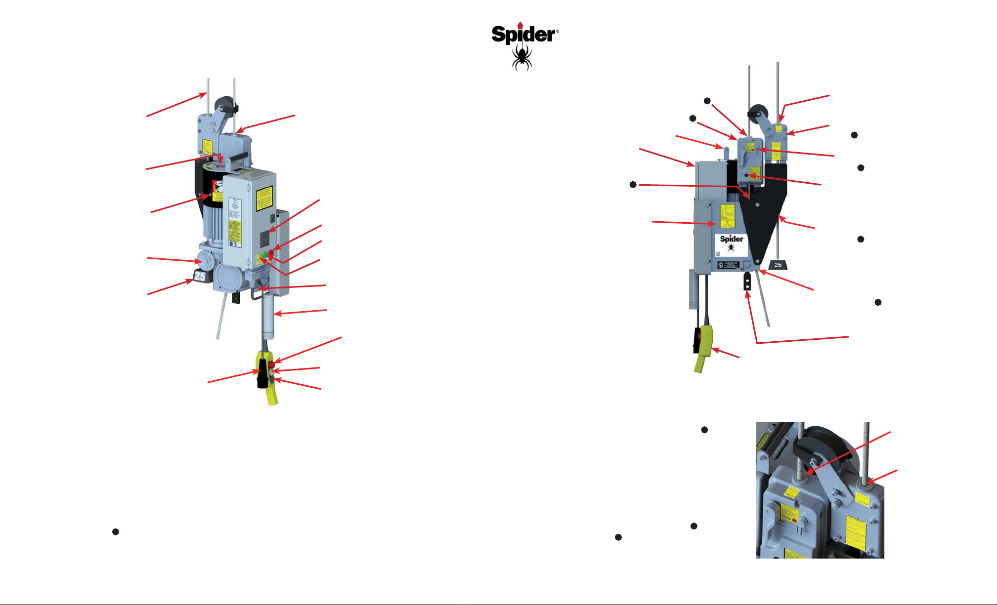
Hoist Operation Quick Reference
UpPro Series Hoists
READ THE OPERATOR’S MANUAL BEFORE USING THIS QUICK REFERENCE
UP Operation Button
Emergency Stop (Power
Supply Cut-off)
GREEN Power Indicator Light
Primary Wire Rope Inlet
DOWN Operation Button
Operating Instructions
Manual and Schematic
Carrying Handle
Power Supply Cable
Primary Suspension
Wire Rope Exit14
Normal Operation
• Switch the control unit on by turing the red emergency stop button on the pendant in the clockwise direction until it pops out.
• For routine travel in the UP direction, push in the UP operation button. For routine travel in the DOWN direction,
push in the DOWN operation button.
• The UP/DOWN buttons have two pressure points. The first pressure point is for the slower speed. Push the UP or
DOWN button again for the faster speed. On 4-speed models, press the
yellow
yellow buttonfor the next highest speed.
• The UP/DOWN buttons are spring-loaded and will return to the OFF positionAND apply the brake when released.
• If the hoist does not immediately stop the platform, press the emergency stopAND turn the overspeed brake
ACTIVATION lever12 in the LOCK direction. Unplug the power supply cable.
• Perform daily testing and inspection (see over) to ensure safe and correct operation. Do NOT use the hoist for
lifting until it has successfully completed the daily tests.
• WARNING! Do NOT operate the hoist if, at any time, you cannot see the flywheel turning.
Platform Mounting
Stirrup Bar
Primary Suspension
Wire Rope Inlet
Inlet for Optional
Secondary
Suspension Wire
Rope
Inlet for Optional
Secondary Wire Rope
721022-1/A
RED Overload Trip Indicator Light
Brake Release Lever
(Storage Position)
Hand Wheel
(Storage Position)
Hour Meter
Optional Secondary Wire Rope
Exit for Optional Secondary
Wire Rope13
Optional Inclination Safety Lock
(ISL)11
Overspeed Brake ACTIVATION
Lever12
Overspeed Brake RESET Lever17
Overspeed Safety Lock (OSL)16
Electrical Box
Traction Compartment
Pendant
Flywheel Observation Window
25-lb Weight for Optional
Secondary Wire Rope
Motor Brake Release Lever
(Operating Position)
Hand Wheel
(Operating Position) Primary Wire Rope Inlet in
Traction Compartment15
YELLOW
YELLOW 2-Speed Button/ Low Voltage
Indicator (3-Phase Models only)

De-reeving Primary Suspension Wire Rope
For hoists equipped with the optional secondary wire rope, the secondary wire rope must be removed before
the primary wire rope is removed.
• WARNING! To prevent hoists and platform from tipping and to avoid injuries, ensure that the platform is
properly supported on a stable, flat surface before putting slack in the primary suspension wire rope.
• Push in the DOWN operation buttonto wind the primary suspension wire rope out of the hoist. When the wire
rope stops moving, pull the wire rope upward out of the overspeed safety lock16 SLOWLY to avoid tripping the
overspeed brake. To release the overspeed brake, run the hoist UP and turn the overspeed brake RESET lever17
clockwise in the UNLOCK direction.
De-reeving Secondary Suspension Wire Rope
• In order to remove the optional secondary suspension wire rope, there must be NO SLACK on the primary
suspension wire rope and the PLATFORM MUST BE SUPPORTED on a flat, stable surface.
• Remove the counterweight from the end of the secondary suspension wire rope.
• Pull the secondary suspension wire rope out of the ISL11 by hand.
• If necessary, the primary suspension wire rope can now be removed from the hoist.
Resetting the Overload
• Push in the emergency stop buttonon the pendant and wait until the RED light on the electrical box goes out.
• Switch the unit on again by turning the emergency stop button clockwise until it pops out.
Daily Testing and Inspection
• Before operating the hoist, inspect all of the following:
Wire rope
Power supply
Rigging
Platform
Hoist
All parts are present, in proper working order, and are not
damaged.
Bolts, nuts, and clamps are well secured.
Ensure the hoist is secured to the stirrup with SAE Grade 5
fasteners and lock nuts that are properly installed.
• In a dirty environment that contains epoxy, paint, cement, sand blast residue, or corrosive material, inspect the operation
of the overspeed brake several times a day. Protective hoist covers are recommended. Contact your supplier.
Test the Emergency Stop Button
• Conduct a test run with the hoist’s maximum working load (2,200 lbs or 1000 kg).
• Press the red emergency stop buttonwhile running the hoist in either direction.
• Once the emergency stop button has been pressed, the hoist should not move at all.
• To reset the emergency stop button, turn the button clockwise until it pops out.
Test the Controlled Descent
• Raise the platform approximately 3 feet (1 meter) and then disconnect the power supply cable.
• Remove the brake release leverfrom its storage cylinder, insert into the opening in the motor cover, and lift the
brake release lever. This will allow the platform to be lowered slowly.
WARNING! If the overspeed brake trips while testing the controlled descent, the controlled descent system is not
working properly and THE HOIST SHOULD NOT BE USED.
Test the Overspeed Brake & Actuation Lever
• While powering the hoist UP and DOWN
approximately 3 feet (1 meter), look through
the round window into the overspeed safety
lock to see whether the flywheel is turning.
• De-reeve the wire rope.
• Re-insert the wire rope about 12" (30 cm) into
the hoist’s OSL wire rope inlet.
• Holding the wire rope firmly, pull it out
quickly. If the overspeed brake is working
correctly, it will grip and hold the wire rope in
less than 4" (10 cm).
• Repeat this test at least 3 times. If the
overspeed brake does not work correctly every
time, DO NOT USE THE HOIST. Return the
hoist to your supplier.
• Release the overspeed brake by turning the
overspeed brake RESET lever17 clockwise in
the UNLOCK direction. The overpseed brake
ACTIVATION lever12 should return to its
vertical, locked position.
• While raising or lowering the hoist, activate the
overspeed brake by turning the overspeed
Flywheel
Observation
Window
Turn overspeed brake
RESET lever17
clockwise
Overspeed brake
ACTIVATION
lever12 returns to
locked position
brake ACTIVATION lever12 on the OSL in the counterclockwise or LOCK direction. The hoist should not travel in
the DOWN direction.
• Release the overspeed brake by turning the overspeed brake RESET lever17 clockwise in the UNLOCK
direction. The overspeed brake ACTIVATION lever12 should return to its vertical, locked position.
Test the Hand Wheel
NOTE: The purpose of the hand wheelis to crank the platform upwards just enough to untrip the overspeed brake if it
has been tripped due to power loss or something else that has prevented upward movement.
• Activate the overspeed brake by turing the overspeed brakeACTIVATION lever12 counterclockwise in the LOCK
direction.
• Remove the small cap in the motor cover and unscrew the screw that retains the hand wheel enough to remove the
hand wheel.Insert the hand wheel into the motor in place of the small cap and tighten the screw.
• Remove the motor brake release leverand insert into the opening in the motor cover. Hold the hand wheel still
while pushing the brake lever up, then turn the hand wheel clockwise. The hoist will move up a small amount with
each turn until the overspeed brake releases and can be reset with the overspeed brake RESET lever17.
Other SPIDER Chain Hoist manuals


Popular Chain Hoist manuals by other brands

Hercules
Hercules H-F 1000 Original operating instructions

R&M
R&M STAGEMAKER SM5 Installation, operation and maintenance instructions

Harrington
Harrington TCS Series owner's manual

SVERO
SVERO 20123A manual

Yale Industrial Products
Yale Industrial Products TIGRIP TBL 0,5 operating instructions

Sumake
Sumake SA-22030 Operation manual


