SPIDER SC1500-GHS User manual

Hoist Operation Quick Reference
Spider SC1500-GHS Hoist
READ THE OPERATOR’S MANUAL BEFORE USING THIS QUICK REFERENCE
Normal Operation
• For routine travel in the UP direction, press the UP operation button.
• For routine travel in the DOWN direction, press the DOWN operation button.
• Both buttons are spring-loaded and will return to the OFF position AND apply the brake when released. If the hoist does
not immediately stop, press the emergency stop buttonAND the overspeed brake test button.
Unplug the power supply cable.
• Perform daily testing and inspection (see other side of this quick reference) to ensure safe and correct operation. Do NOT
use the hoist for lifting until it has successfully completed the daily tests.
Reeving
• Push the primary suspension wire rope through the primary
suspension wire rope insertion pointapproximately
15 inches.
• Operate the hoist in the UP direction while a second person
pushes the wire rope into the hoist.
• Ensure the wire rope runs freely through the wire rope exit
guide.
• If the hoist is equipped with an optional secondary
suspension wire rope, push the secondary suspension wire
rope through the secondary suspension wire rope insertion
point until it exits the hoist.
• Attach a 25-lb weight to the end of the secondary wire rope
to assist secondary wire rope travel.
Primary
Suspension
Wire Rope
Secondary Wire Rope 11
721049-1/A
Wire Rope
Exit Guide
Motor
Traction
Compartment
Name
Plate
11
GREEN Power
Indicator Light
Overspeed Brake
Test Button
Lifting Handle
Power Supply Cable
Remote Receptacle
Primary Wire Rope
Insertion Point
Hour Meter Voltage
Indicator
Electrical
Compartment
Controlled
Descent Lever 14
Wire Rope Insertion
Point for Optional
Secondary Wire Rope 11 RED Overspeed
Brake Trip
Indicator Light 13
Overspeed Reset
Knob 12
Emergency Stop
Button
↑UP Button
↓DOWN Button
De-reeving Secondary Suspension Wire Rope
• The secondary suspension wire rope MUST be de-reeved before the primary suspension wire rope.
• In order to remove the optional secondary suspension wire rope, there must be no slack on the primary suspension wire
rope and the platform must be supported on a stable surface.
• Remove the counterweight from the end of the secondary suspension wire rope.
• Pull the secondary suspension wire rope out of the hoist by hand.
• If necessary, the primary suspension wire rope can now be removed from the hoist.
De-reeving Primary Suspension Wire Rope
• The secondary suspension wire rope MUST be de-reeved before the primary suspension wire rope.
• WARNING! To prevent hoists and platform from tipping and avoid injuries, ensure that the platform is properly
supported on a stable, flat surface before putting slack on the primary suspension wire rope.
• Press the DOWN operation buttonto de-reeve the primary suspension wire rope out of the hoist. To remove the
last 15 inches of wire rope, if necessary, grab the wire rope above the primary suspension wire rope insertion point,
hold the overspeed brake reset knob12 in the reset position (vertical) and slowly pull the primary suspension wire rope
out of the hoist.
Daily Testing and Inspection
• Before operating the hoist, inspect the following:
▫Wire rope
▫Power supply
▫Rigging
▫Platform
▫Hoist
▫All parts are present, in proper working order, and are not damaged.
▫Bolts, nuts, and clamps are well secured.
▫Ensure the hoist is secured to the stirrup with SAE Grade 5 fasteners and lock nuts that are properly installed.
• In a dirty environment that contains epoxy, paint, cement, sand blast residue, or corrosive material, inspect the
operation of the overspeed brake several times a day. Protective hoist covers are recommended. Contact your supplier.
Test the Controlled Descent
• Raise the platform approximately 3 feet.
• Disconnect the power supply.
NOTE: Failure to disconnect the power supply before testing the controlled descent will activate the overspeed,
resulting in an inaccurate controlled descent test.
• Lift the controlled descent lever 14 .
NOTE: The controlled descent lever released the motor brake, which will allow the platform to be lowered slowly
during controlled descent.
WARNING! If the overspeed brake trips while testing the controlled descent with the power supply disconnected, the
controlled descent system is not working properly and THE HOIST SHOULD NOT BE USED.
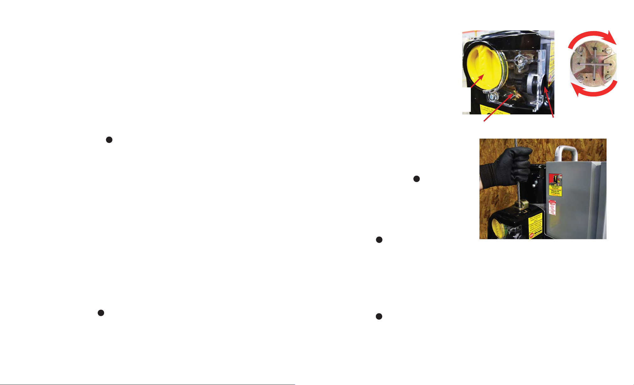
Test the Overspeed Brake
• While powering the hoist UP and DOWN
approximately 3 feet, look through the window
into the overspeed compartment to see whether
the flywheel is turning.
NOTE: Do NOT use the hoist if you cannot
see the flywheel turning.
Flywheel Overspeed Brake
Test Button
Flywheel
Movement
Overspeed Brake
Reset Knob (in
reset position)
• De-reeve the wire rope.
• Re-insert the wire rope about 12" into the hoist.
• Holding the wire rope firmly, pull it out quickly. If
the brake is working correctly, it will grab and hold
the wire rope in less than 4". When the DOWN
button is pressed, the RED light 13 in the electrical
box will illuminate to indicate the overspeed brake
has been activated and the DOWN circuit has been
interrupted.
• Repeat this test at least 3 times. If the brake does
not work correctly every time, DO NOT USE THE
HOIST. Return the hoist to your supplier.
• Reset the overspeed brake by turning the overspeed
brake reset knob 12 clockwise.
Test the Overspeed Brake Test Button
• Press the UP operation buttonand raise the platform approximately 3 feet.
• Press the DOWN operation button,and, at the same time, press the overspeed brake test button.
• The platform should stop immediately. WARNING! If the hoist does not immediately stop the platform when the
overspeed brake test buttonis pushed, this indicates the motor is out of phase. Stop pushing all three buttons and
CORRECT THE PROBLEM BEFORE THE HOIST IS PUT IN SERVICE.
• Reset the overspeed brake by powering the hoist UP a few inches to disengage the brake and then turn the overspeed
brake reset knob 12 clockwise.
Test the Emergency Stop Button
• While running the hoist in either direction, have a second person press the red emergency stop button.
• Once the emergency stop buttonhas been pressed, the hoist should not move at all.
• To reset the emergency stop button, twist clockwise until the button pops out.
Other SPIDER Chain Hoist manuals


Popular Chain Hoist manuals by other brands


POWERTEX
POWERTEX PSBS-S2/2T-75-10 Instructions for use

Ingersoll-Rand
Ingersoll-Rand Liftchain LC2H060S Product Maintenance Information

Haklift
Haklift VANOS250 Original instructions

POWERTEX
POWERTEX PCB-S2 user manual

CHANCE
CHANCE C312-0000 Installation, operating & servicing instructions

Matrix
Matrix EH 1600/1000-1 instructions

William Hackett
William Hackett WH-C4 Safety information

Yale
Yale UNOplus A Series Translated Operating Instructions

KITO
KITO Harrington TCK Series owner's manual

Liftket
Liftket STAR LIFTKET VFD Operating Instructions Supplementary Sheet

CM
CM 653 Series Operating, Maintenance & Parts Manual

RGC
RGC HANDIHOIST instructions