SPIERINGS AT4 User manual

MANUAL SPIERINGS TRUCK AT4
AT4-EN-050819.doc I
Preface
Dear user,
This operating manual provides the user of the Spierings folding crane with information concerning the crane's
construction and operation. You will find detailed technical specifications and maintenance instructions in the
maintenance part of this manual.
© Copyright Spierings Cranes.
All rights reserved.
No part of this publication may be reproduced or published, in any form or in any way, by print, photo print, microfilm or any other means without prior permission from the
manufacturer.

MANUAL SPIERINGS TRUCK AT4
AT4-EN-050819.doc II
Liability clause
SECTION 1. OPERATION
1.1 The Spierings truck may only be used for the purpose it was manufactured and designed for and only as
described in the user manual or in the additions to it.
1.2 Any use of the Spierings truck that differs from its design purpose or as described in the use manual or
the additions to it, will cause the product warranty and the manufacturer’s liability, for any direct or
indirect damage, to expire.
1.3 Only qualified, skilled personnel are allowed to operate the truck. The driver should have a special
driving license for driving heavy vehicles. The driver/operator must be in good physical and mental
health, so that he/she is able to carry out the work without restrictions and react with responsibility in all
given situations.
1.4 The driver/operator/user of the Spierings truck should be informed immediately of any additions/changes
to the user manual.
SECTION 2. SAFETY
2.1 For safety reasons the driver/operator/user should carry out all operations as stated in the user manual
or in the additions to it.
2.2 If more stringent safety demands are locally placed on the truck/crane than specified in the Spierings
truck user manual or additions to it, these more stringent requirements must be strictly complied with. If
not, all warranty will expire and the manufacturer will not be liable for any damage or costs.
2.3 The Spierings truck manufacturer points out explicitly, that the driver/operator/user and local personnel
should not enter the cranes/trucks danger zone. If, for any reason or cause, an unexpected situation
occurs during operation one should contact the technical department or Spierings Service department
first before proceeding.
SECTION 3. WARRANTY
3.1 It is prohibited to carry out modifications or welding to the Spierings truck without prior written permission
of the manufacturer of the Spierings truck.
3.2 Frequent maintenance and periodic checks should be carried out in accordance with the user manual, or
in the additions to it. If maintenance or checks are carried out otherwise, or less frequent, without prior
written permission of the manufacturer of the Spierings truck, all warranty will expire and any liability, for
direct or indirect damage, is explicitly excluded.

MANUAL SPIERINGS TRUCK AT4
AT4-EN-050819.doc III
Explanation of the symbols used
CAUTION!
Wear safety goggles!
Wear safety gloves!
Wear safety boots!
Wear head protection!
Use safety belt!
Check!
Manual action!
Automatic action!
Wrong!
Right!
Information!

MANUAL SPIERINGS TRUCK AT4
AT4-EN-050819.doc IV
Index
PREFACE ................................................................................................................................................................ I
LIABILITY CLAUSE................................................................................................................................................ II
EXPLANATION OF THE SYMBOLS USED .......................................................................................................... III
INDEX .................................................................................................................................................................... IV
1. GENERAL DATA AT4 .............................................................................................................................. 1-1
2. OPERATION............................................................................................................................................. 2-1
2.1. Get to know the truck .................................................................................................................. 2-1
2.2. Truck cab .................................................................................................................................... 2-3
2.2.1. Getting in ....................................................................................................................... 2-3
2.2.2. Doors............................................................................................................................. 2-3
2.2.3. Wing mirrors .................................................................................................................. 2-3
2.2.4. Seats ............................................................................................................................. 2-4
2.2.5. Safety belts....................................................................................................................2-4
2.2.6. Storage room................................................................................................................. 2-4
2.2.7. Sun blind .......................................................................................................................2-4
2.2.8. Fuse box........................................................................................................................2-4
2.2.9. Windscreen washer reservoir ........................................................................................ 2-4
2.2.10. Central lubrication system (optional) ........................................................................... 2-5
2.2.11. Battery charger remote control batteries ..................................................................... 2-5
2.2.12. Fire extinguisher .......................................................................................................... 2-5
2.3. Control panel............................................................................................................................... 2-6
2.4. Driving the Spierings crane ....................................................................................................... 2-13
2.4.1. Starting ........................................................................................................................2-13
2.4.2. Turning off the engine.................................................................................................. 2-14
2.5. Driving on the road.................................................................................................................... 2-14
2.6. Braking system.......................................................................................................................... 2-14
2.6.1. Operating brake........................................................................................................... 2-14
2.6.2. Parking brake .............................................................................................................. 2-15
2.6.3. Vacuum brake/engine stop .......................................................................................... 2-15
2.6.4. Slowing down using the retarder (optional) ................................................................. 2-15
2.7. Retarder/ESC/CC...................................................................................................................... 2-16
2.7.1. The Bremsomat ........................................................................................................... 2-16
2.7.2. Cruise Control (CC) ..................................................................................................... 2-16
2.7.3. Variable vehicle speed limit ......................................................................................... 2-17
2.7.4. Speed control (ESC).................................................................................................... 2-17
2.8. Driving off the road.................................................................................................................... 2-18
2.8.1. Off the road gear shift high/low transfer case .............................................................. 2-18
2.8.2. Longitudinal differential lock ........................................................................................ 2-18
2.8.3. Transverse differential lock.......................................................................................... 2-19
2.9. Parking ...................................................................................................................................... 2-19
2.10. Axle height adjustment .............................................................................................................. 2-19
2.11. Independent rear axle steering..................................................................................................2-21
2.11.1. Driving with independent rear axle steering............................................................... 2-21
2.11.2. Limits of using the independent rear axle steering .................................................... 2-22
2.11.3. Disengage the independent rear axle steering .......................................................... 2-22
2.12. Driving with erected tower ......................................................................................................... 2-22
2.13. Driving with a trailer................................................................................................................... 2-23

MANUAL SPIERINGS TRUCK AT4
AT4-EN-050819.doc V
2.14. Towing the crane....................................................................................................................... 2-23
2.14.1. Towing when the diesel engine can still run .............................................................. 2-23
2.14.2. Towing when the diesel engine is out of order........................................................... 2-24
3. MAINTENANCE........................................................................................................................................ 3-1
3.1. General ....................................................................................................................................... 3-1
3.1.1. Clothing ......................................................................................................................... 3-1
3.1.2. Surroundings ................................................................................................................. 3-1
3.1.3. Diesel engine................................................................................................................. 3-1
3.1.4. Moving parts .................................................................................................................. 3-1
3.1.5. Oils and coolant............................................................................................................. 3-2
3.1.6. Environment .................................................................................................................. 3-2
3.1.7. Refreshing oil/cooling system ........................................................................................ 3-2
3.1.8. Fire-risk ......................................................................................................................... 3-2
3.1.9. Cleaning of components................................................................................................ 3-2
3.2. Maintenance plan AT4 truck........................................................................................................ 3-3
4. DIESEL ENGINE....................................................................................................................................... 4-1
4.1. Services in the first period of use ................................................................................................ 4-1
4.2. Access to the diesel engine......................................................................................................... 4-2
4.3. Engine oil .................................................................................................................................... 4-2
4.3.1. Check engine oil level.................................................................................................... 4-2
4.3.2. Fill up engine oil............................................................................................................. 4-3
4.3.3. Engine oil change .......................................................................................................... 4-3
4.4. Engine oil filter............................................................................................................................. 4-4
4.4.1. Oil filter replacement...................................................................................................... 4-4
4.5. Cooling system............................................................................................................................ 4-5
4.5.1. Check coolant level ....................................................................................................... 4-5
4.5.2. Fill up coolant ................................................................................................................ 4-6
4.5.3. Change coolant ............................................................................................................. 4-6
4.5.4. Anti-frost ........................................................................................................................ 4-7
4.5.5. Radiator and intercooler ................................................................................................ 4-7
4.6. Air inlet system............................................................................................................................ 4-8
4.6.1. Cleaning the air filter...................................................................................................... 4-8
4.6.2. Air filter cartridge change............................................................................................... 4-9
4.7. Fuel system................................................................................................................................. 4-9
4.7.1. Fuel filter change ........................................................................................................... 4-9
4.8. Fuel filter/Water separator......................................................................................................... 4-11
4.8.1. Drain the water separator ............................................................................................ 4-11
4.8.2. Fuel filter/water separator change ............................................................................... 4-12
4.9. V-belts ....................................................................................................................................... 4-12
4.9.1. Check the V-belts ........................................................................................................ 4-12
4.9.2. Adjust the V-belts ........................................................................................................ 4-13
4.9.3. Gear belt check ........................................................................................................... 4-14
4.9.4. Gear belt adjustment ................................................................................................... 4-15
4.10. Exhaust system......................................................................................................................... 4-15
4.11. Check and adjust the valve clearance....................................................................................... 4-16
4.12. Check and adjust the DEB clearance........................................................................................ 4-17
5. DRIVE LINE .............................................................................................................................................. 5-1
5.1. Clutch and gear box .................................................................................................................... 5-1
5.1.1. Specifications gear box ................................................................................................. 5-1
5.1.2. Maintenance gear box ................................................................................................... 5-2
5.1.3. Check oil level of the gear box....................................................................................... 5-2

MANUAL SPIERINGS TRUCK AT4
AT4-EN-050819.doc VI
5.1.4. Gear box oil change ...................................................................................................... 5-3
5.2. Transfer case .............................................................................................................................. 5-3
5.2.1. Specifications transfer case........................................................................................... 5-3
5.2.2. Maintenance transfer case ............................................................................................ 5-3
5.2.3. Check oil level transfer case.......................................................................................... 5-4
5.2.4. Transfer case oil change ............................................................................................... 5-4
5.3. Axles ........................................................................................................................................... 5-5
5.3.1. Maintenance axles......................................................................................................... 5-5
5.3.2. Check oil level differentials ............................................................................................ 5-5
5.3.3. Differential oil change .................................................................................................... 5-6
5.3.4. Check oil level hubs....................................................................................................... 5-7
5.3.5. Hubs oil change............................................................................................................. 5-7
5.4. Tires ............................................................................................................................................ 5-8
5.4.1. Maintenance tires .......................................................................................................... 5-8
5.4.2. Tire pressure ................................................................................................................. 5-8
5.5. Check the brake lining thickness................................................................................................. 5-8
5.5.1. Brakes ........................................................................................................................... 5-8
5.6. Clutch .......................................................................................................................................... 5-8
5.6.1. Checking the clutch ....................................................................................................... 5-8
5.6.2. Venting the clutch .......................................................................................................... 5-9
5.6.3. Clutch fluid change ...................................................................................................... 5-10
6. STEERING SYSTEM ................................................................................................................................ 6-1
6.1. Check the steering system .......................................................................................................... 6-2
6.2. Align the steering system ............................................................................................................ 6-2
7. ELECTRICAL SYSTEM............................................................................................................................ 7-1
7.1. Lighting........................................................................................................................................ 7-1
7.2. Dashboard lighting ...................................................................................................................... 7-1
7.3. Batteries ...................................................................................................................................... 7-2
7.3.1. Check the batteries........................................................................................................ 7-2
7.3.2. Recharging the batteries ............................................................................................... 7-2
7.3.3. Replacing batteries........................................................................................................ 7-3
8. HYDRAULIC SYSTEM ............................................................................................................................. 8-1
8.1. Check oil level hydraulic tank ...................................................................................................... 8-1
8.2. Hydraulic oil change.................................................................................................................... 8-2
8.3. Hydraulic return filter change ...................................................................................................... 8-3
8.3.1. Hydraulic return filter ..................................................................................................... 8-3
8.4. Check the suspension’s accumulators ........................................................................................ 8-3
8.5. Hoses and connections hydraulic system ................................................................................... 8-4
9. PNEUMATIC SYSTEM ............................................................................................................................. 9-1
9.1. Primary system: brake system ....................................................................................................9-1
9.2. Secondary system: accessories and gearbox ............................................................................. 9-1
9.3. Air dryer....................................................................................................................................... 9-2
9.3.1. Air dryer filter change .................................................................................................... 9-2
9.4. Air vessels................................................................................................................................... 9-3
9.5. Air lubricator/water separator ...................................................................................................... 9-3
9.5.1. Refill air lubricator.......................................................................................................... 9-4
9.5.2. Water separator............................................................................................................. 9-4
9.6. Check brake pressure ................................................................................................................. 9-5

MANUAL SPIERINGS TRUCK AT4
AT4-EN-050819.doc VII
9.7. Hoses and connections pneumatic system ................................................................................. 9-5
10. LUBRICATION........................................................................................................................................ 10-1
10.1. Central lubrication system (Option) ........................................................................................... 10-1
10.1.1. Timer central lubrication system ................................................................................ 10-1
10.1.2. Grease reservoir central lubrication system .............................................................. 10-1
10.1.3. Greasing points central lubrication system ................................................................ 10-2
10.2. Manual lubrication ..................................................................................................................... 10-3
10.2.1. Outrigger beam cylinders .......................................................................................... 10-3
10.2.2. Driven axles............................................................................................................... 10-3
10.2.3. Cardan shafts ............................................................................................................ 10-4
10.2.4. Steering system......................................................................................................... 10-4
10.2.1. Tower supports.......................................................................................................... 10-5
11. VARIOUS................................................................................................................................................ 11-1
11.1. Window washer fluid ................................................................................................................. 11-1
11.2. Fire extinguisher........................................................................................................................ 11-1
12. TECHNICAL DATA................................................................................................................................. 12-1
13. ENCLOSURES ....................................................................................................................................... 13-1

MANUAL SPIERINGS TRUCK AT4
AT4-EN-050819.doc 1-1
1. General Data AT4
The AT4 carriage is especially designed for the Spierings SK488 folding crane. Extra attention is paid to a smooth
and c omfortable transp ort to the work site. The crane is s uited for driving on public r oads, full y equipped with
counterweight and tools. The chassis is an especially rigid structure to create a good crane support.
In Picture 1-1 you will find the measurements of the SK488 with the AT4 carriage. The dimensions given are the
overall dimensions, axle bases and turning circle.
Picture 1-1
Measurements:
• Len gth: 15,8m
• W idth: 2,8m
• Heig ht: 4m
Drive unit:
• 12,6 litre DAF-diesel engine with turbo compressor and intercooler (type XE 315).
• ZF gearbox with sixteen gears forward and two gears reverse.
• STEYR high/low shift, transfer case, with high speed (road) and low speed (off the road) transmission.
• Electronic accelerator "E-gas” with speed control.
• Four Ginaf axles, where axle two, three and four are driven.

MANUAL SPIERINGS TRUCK AT4
AT4-EN-050819.doc 1-2
Steering:
• Axle 1, 2 en 4 are steered.
• Mechanically coupled steering, where axle four is steered in the opposite direction of axle one and two,
realizing a small turning circle.
• As option, axle 4 can be mechanically uncoupled and manually steered in the same steering direction as axle
1 and 2 using a joystick. When axle 3 is lifted, sideway driving is possible.
• Hydraulically powered steering system.
• Fitted with an emergency steering pump, so when the main steering pump malfunctions, the truck remains
steer able until it is at a standstill.
• Provisions for driving off the road:
- axle height adjustable
- high/low gear shift transfer case can be put in low gear for driving off the road
- longitudinal and transverse differentials can be locked
Suspension:
• H ydro-pneumatic suspension.
• The suspension can be blocked (e.g. when driving with erected tower.)
Braking system:
• Pneumatic brakes with anti-blocking system (ABS).
4-point outrigger system:
• wide support base = 6,9 m x 6,85 m
• Narrow support base = 6,9 m x 5,15 m
Further data:
• Maximum speed limit to 85 km/h
• Minimum speed at 1250 rpm: 1,9 km/h (is 32 m/min)
• Truck weight including superstructure: 48.000 kg
• De axle load is 12.000 kg per axle
MANUAL SPIERINGS TRUCK AT4
AT4-EN-050819.doc 1-3
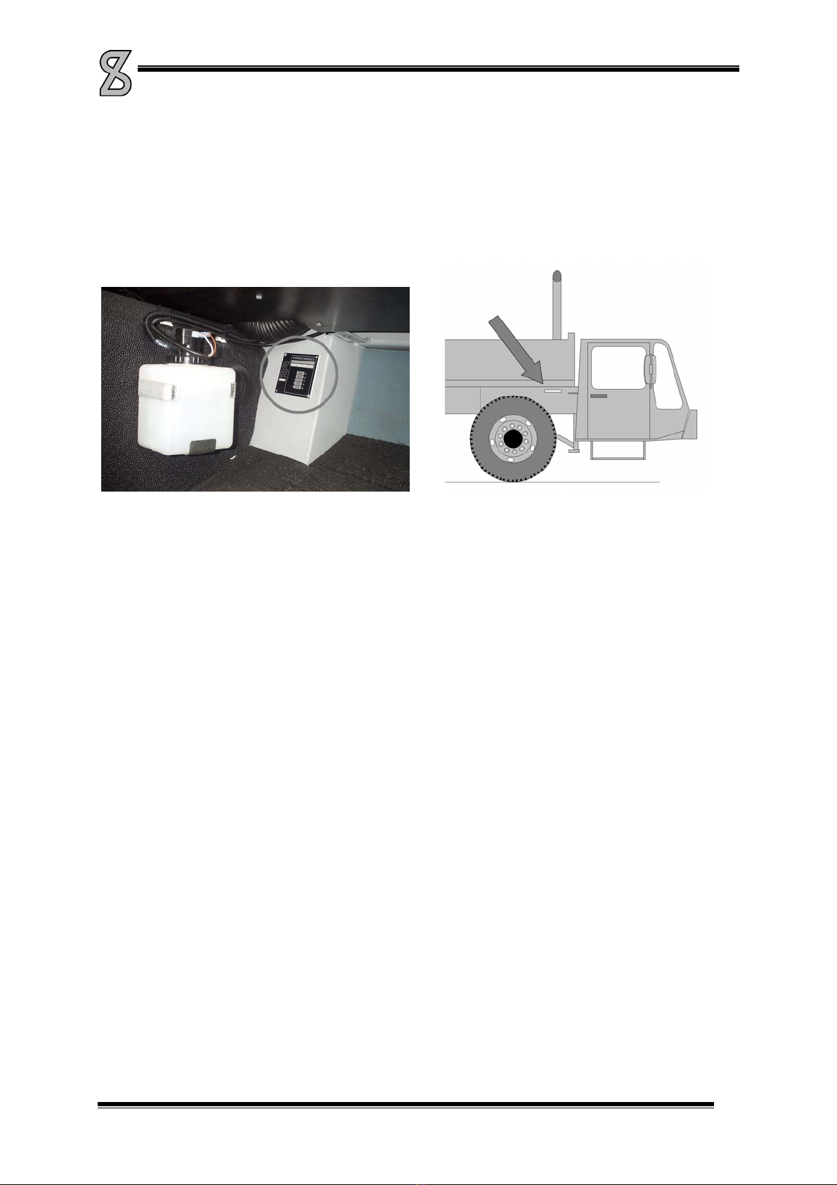
Identification:
• Engine number: Left-hand on the engine block above the fuel pump.
Vehicle identification number: On the identification plate in the co-driver’s leg-room (See Picture 1-2) and
stamped in the right frame girder in front of the first axle. (Picture 1-3)
Picture 1-2
Picture 1-3

MANUAL SPIERINGS TRUCK AT4
AT4-EN-050819.doc 2-1
2. Operation
2.1. Get to know the truck
Picture 2-1
1. T ruck cab
Besides driving the crane, with the controls in the truck cab you can support the crane on outriggers and adjust
the carriage axle height.
2. Storage box/battery box/battery switch
In this storage box, the batteries are placed. To the right side of this box, you’ll find the battery switch.
3. Hydraulic oil tank
On this side of the truck you will find the hydraulic oil tank.
4. Sto rage box
This box is lockable and can be used for hoisting equipment.
5. o utriggers
At both sides of the truck there are 2 extending outrigger beams (Picture 2-2, 4), and to each beam a hydraulically
operated outrigger (1). These outriggers provide stability during hoisting operation. The outrigger beams have an
antiskid coating (5) to prevent skidding. The outrigger pad holders (3) can be used to facilitate stepping on the
outrigger beam (2).
With a separate (remote) control box the outriggers can be radio controlled. On the rear outrigger beams are
levels to check if the crane set-up is level.

MANUAL SPIERINGS TRUCK AT4
AT4-EN-050819.doc 2-2
Picture 2-2
6. Storage room support plates
To obtain a solid support base on a week ground, support plates can be used. Under the toolbox as well as under
the fuel tank there are 2 support plates each.
7. Fue l tank
The fuel tank capacity is 400 liters.
8. Bu mper
The crane has a standard bumper at the rear. When the bumper is folded up, the towing hook can be used.
9. J ib turning pipe
Through a hole in the deck you can reach the jib turning pipe. This pipe is used to swing the jib in front of the
tower during erecting and folding the crane.
10. W ork lamps
To the rear of the cab and truck are mounted work lamps, which can be
switched on/off from the cab.
By unscrewing the knob, the lamp support can be moved to the left and right
(see Picture 2-3).
Picture 2-3
11. T ruck ladders
To facilitate getting on the truck, three ladders are mounted. Pick up the
free end of the ladder so the pin comes out of the deck (see Picture 2-4)
and swing the ladder outside the frame. When swinging back the ladder,
make sure the pin returns in the hole.
Picture 2-4
12. Concrete bucket/brick gripper support (optional)
On the bumper a support can be mounted to carry a concrete bucket or a brick gripper.

MANUAL SPIERINGS TRUCK AT4
AT4-EN-050819.doc 2-3
13. Slin g box
On this location you can install a sling box to store your chains and slings. The sling box can be turned aside so
the engine housing remains accessible.
14. Spare tire/Sling box/pallet hook support/Hullo clamp support (optional)
On this location you can install one of the following options
Spare tire support. The spare tire support is fitted with a winch and is mounted on a swing frame. When you swing
the frame out you can lower the spare tire with the winch.
• Slin g box
• Pallet hook support
• Hullo clamp support
All these options can be turned aside so the engine housing remains accessible.
15. Central lubrication system (optional)
This is the grease reservoir for the truck’s optional central lubrication system.
16. Toolbox at the rear (optional)
For extra storage room a toolbox can be mounted all along the rear of the truck.
17. Rear- and side view cameras (optional)
To broaden your view at the rear and right-hand side of the truck cameras can be installed. In the cab a monitor is
installed, showing the camera view.
Standard, the view of the side camera is shown. When putting the transmission in reverse, the monitor
automatically switches over to rear camera view.
2.2. Truck cab
In the truck cab you drive the crane safely and comfortably to its destination. This chapter makes you familiar with
the cab.
2.2.1. Gettin g in
Use the step under the door. Make use of the steering wheel to hold on to.
2.2.2. Do ors
Turn the handle up to open the door from the inside. The door can only be locked up from the outside.
There is an ashtray on the inside of the door. After opening the ashtray, you push the locking device down to
remove the ashtray from the holder to empty it.
Use the switches on the dashboard to operate the door windows electronically.
2.2.3. W ing mirrors
The wing mirrors may be adjusted by hand. Make sure the mirrors are adjusted before driving off, so that you
have satisfactory view. The mirror heating can be switched on with the switch on the control panel.
MANUAL SPIERINGS TRUCK AT4
AT4-EN-050819.doc 2-4
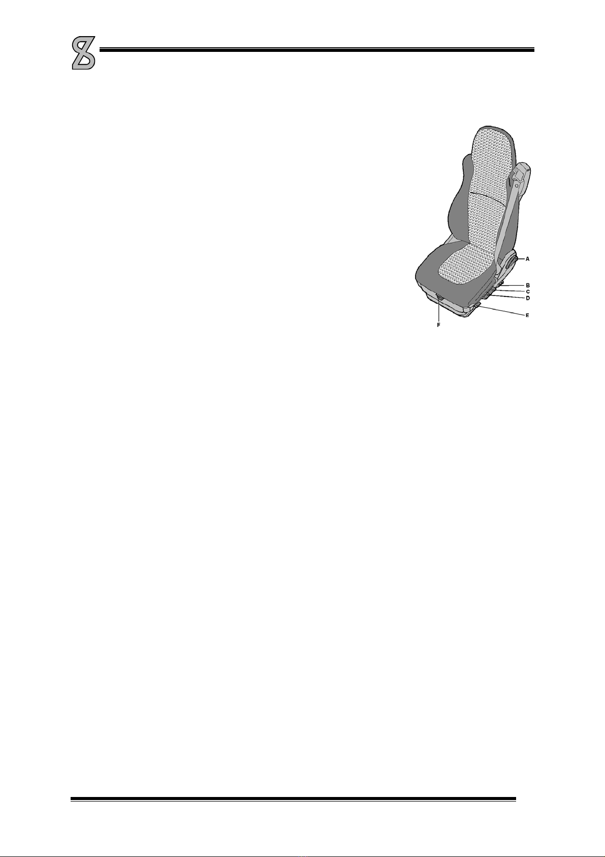
2.2.4. Seats
The cab has room for the driver and a co-driver. The driver's seat has pneumatic
suspension. The seats' position can be adjusted. This should only be done when
the vehicle stands still.
A) Back adjustment
B) Lumbar support adjustment (push = pumping up an pull = deflating)
C) Height adjustment (pulling the handle = up and pushing it = down)
D) Tipping the seat
E) Handle fast lowering
F) Adjustme nt seat
Picture 2-5
2.2.5. Safet y belts
The seats are fitted with safety belts. Driver and co-driver must wear them when driving. Do not modify the belt or
its attachment by yourself. Regularly check its operation by jerking the belt from its winding mechanism. The belt
must lock when doing this. Have the locking device repaired or replaced when it does not function properly. When
the belt was heavily loaded during a collision, it must be completely replaced, even if it looks like there is nothing
wrong with it.
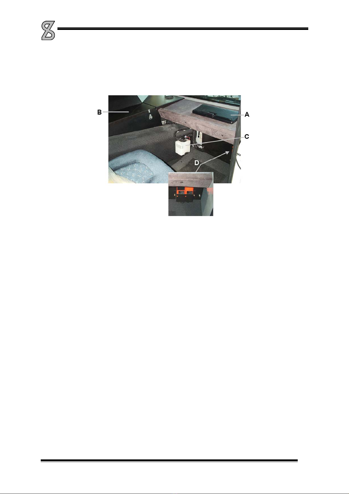
2.2.6. Sto rage room
In the middle of the cab ceiling is a storage compartment. It has a lockable lid at the driver's side and at the side
of the co-driver. There is another storage compartment at the co-driver's side in the dashboard. (Picture 2-6, A)
2.2.7. Su n blind
To prevent sunlight from blinding you, a sun blind is mounted above the windscreen for the driver and the co-
driver. Pull down the blind with the joggle in the middle of the blind. The blind will remain in the desired position.
Push the button on the side of the blind to roll it up
2.2.8. F use box
The fuse box is at the co-driver's side in the centre console (Picture 2-6, B). You will find the fuses listed in the
enclosures.
2.2.9. Windscreen washer reservoir
(Picture 2-6, C)
MANUAL SPIERINGS TRUCK AT4
AT4-EN-050819.doc 2-5
2.2.10. Central lubrication system (optional)
The central lubricating system controls are on the centre panel at the co-driver's side. It can be opened by means
of 2 clamps (Picture 2-6, B).
Picture 2-6
2.2.11. Battery charger remote control batteries
You will find the battery charger for the remote controls on the left under the dashboard at the driver's side
(Picture 2-6, D).
Every remote control comes with 2 batteries each. While the batteries are charged, the indicator lamp lights up.
As soon as they are fully charged, the lamp starts flashing.
2.2.12. Fire extinguisher
One fire extinguisher is behind the co-driver's seat. On the right behind the control box in the crane cab is the
second fire extinguisher.
The fire extinguishers must be inspected every year by the authorities
MANUAL SPIERINGS TRUCK AT4
AT4-EN-050819.doc 2-6
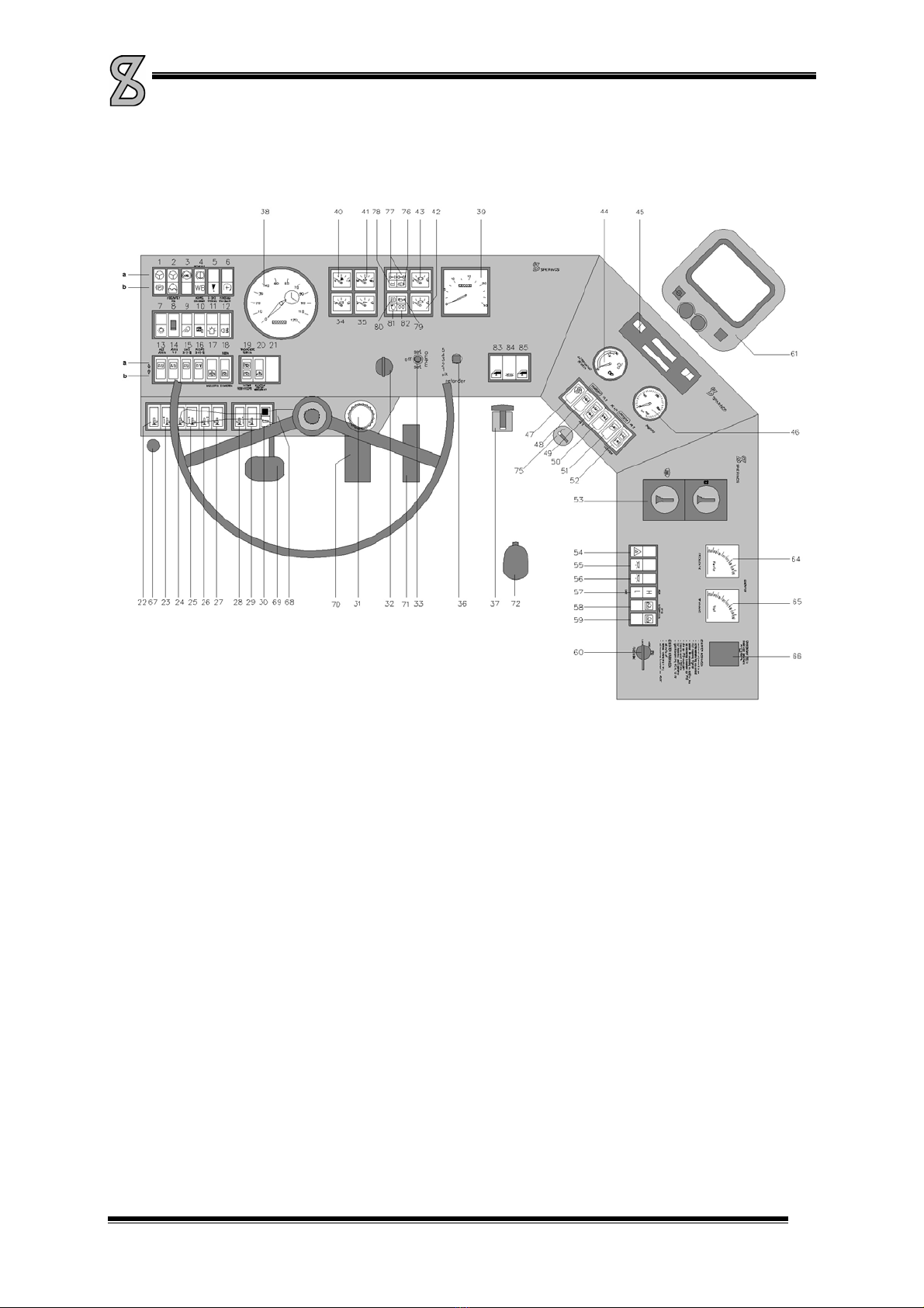
2.3. Control panel
Picture 2-7
1a Indicator lamp steering pressure circuit
1b Indicator lamp parking brake
2a Indicator lamp steering pressure circuit 2
2b Indicator lamp coolant level
3 Sw itch/Indicator lamp ABS
4a Indicator lamp retarder on (optional)
4b Not in use
5a ESC malfunction diagnosis lamp
5b Indicator lamp sensor intermediate position
6 Not in use
7 Light switch, off/parking light/dipped beam
8 D immer dashboard lighting
9 S witch work lamps
10 Switch mirror heating
11 Switch rotating beacon
12 Switch fog tail-light
13 Switch alls axles up/down
14 Switch axles 1 and 2 up/down
15 Switch axle 3 and 4 left-hand side up/down
16 Switch axle 3 and 4 right-hand side up/down
17 Switch/indicator lamp levelling
18 Sw itch driving/blocking
19a Indicator lamp off the road mode
19b Indi cator lamp blocking
20 Indicator lamp max. pressure outrigger-
/suspension system
21 Not in use
22 Switch outrigger beam front left-hand side
retract/extend
23 Switch outrigger front left-hand side
retract/extend
24 Switch outrigger beam rear left-hand side
retract/extend
25 Switch outrigger rear left-hand side
retract/extend
26 Switch outrigger front right-hand side
retract/extend
27 Switch outrigger beam front right-hand side
retract/extend
28 Switch outrigger rear right-hand side
retract/extend
29 Switch outrigger beam rear right-hand side
retract/extend
30 Switch outrigger controls on/off
31 R eservoir clutch fluid
32 Ig nition lock
33 Spee d control
34 Vol tmeter batteries
35 Oil-pressure gauge (lubrication circuit)
36 Switch retarder control
37 Lever parking brake
38 Tachograph, speedometer, mileage counter,
clock
39 Revolution counter, hour counter
40 Fuel gauge
41 Coolant temperature gauge
42 Air-pressure gauge circuit 2
43 Air-pressure gauge circuit 1
44 Oil temperature gauge retarder (optional)
45 R adio
46 Gauge pump pressure steering system
47 Indicator lamp oil temperature WSK (optional)
48 Switch/indicator lamp transverse differential
lock axle 2,3 and 4
49 Indicator lamp transverse differential lock
axle 2 and 3
50 Indicator lamp transverse differential lock
axle 4
51 Switch/indicator lamp longitudinal differential
lock
52 Indicator lamp longitudinal differential lock
53 C ontrol heater/fan
54 Switch alarm light
55 Switch cab lighting on the left
56 Switch cab lighting on the right
57 Indicator lamp high/low gear shift
58 Indicator lamp transfer case neutral
59 Switch transfer case neutral
60 Switch position transfer case high/low/neutral
61 Monitor reverse-/side camera (optional)
62 Gr ound switch
64 Mot in use
65 Not in use
66 Not in use
67 Vacuum brake/engine stop
68 Switch for blinker, windscreen wiper, horn,
signal, full beam headlamp
69 C lutch pedal
70 Br ake pedal
71 A ccelerator pedal
72 Lever range selector with splitter
75 C igarette lighter/24V-connection
76 Indicator lamp charging voltage batteries
77 Indi cator lamp blinker
78 I ndicator lamp air-pressure
79 Indicator lamp full beam headlight
80 Indicator lamp oil pressure (transmission oil)
81 Indicator lamp air cleaner
82 Indicator lamp flame starting system
83 Control electrical window (left-hand)
84 Switch aeronautical warning light on jib and
tower (optional)
85 Control electrical window (right-hand)
MANUAL SPIERINGS TRUCK AT4
AT4-EN-050819.doc 2-7
1a. Indicator lamp steering pressure circuit 1
This Lamp lights up as soon as the oil pressure in steering circuit 1 is too low. Have the malfunction
repaired as soon as possible. If this lamp lights together with lamp 2a: STOP IMMEDIATELY!
1b. Indicator lamp parking brake
As long as the parking brake is engaged, this lamp is on (when starting the engine the parking
brake remains engaged as long as the air-pressure is below 5.5 bar (80 PSI).
2a. Indicator lamp steering pressure circuit 2
This lamp lights up as soon as the oil pressure in steering circuit 2 is too low. Have the malfunction
repaired as soon as possible. If this lamp lights together with lamp 1a: STOP IMMEDIATELY! When
the vehicle stands still, this lamp will light.
2b. Indicator lamp coolant level
This lamp lights up as soon as the coolant level is too low. Replenish coolant.
3. Indic ator lamp/switch ABS
This lamp is on when operating the ignition and remains on until a driving speed of 7 km/h
(4.4 mph) is reached. From 7 km/h (4.4 mph) it goes out and will only light up in case of a
malfunction. At first, push and release the switch to reset the system. If this doesn’t resolve the
problem, have the malfunction repaired as soon as possible.
5a. E-gas diagnosis lamp
Indicator lamp flashers: Stop the vehicle and switch off the engine to prevent damage on the
vehicle and/or engine.
Indicator lamp lights up: There is a malfunction. Some functions will not work correctly. You can
drive the vehicle but repair the problem as soon as possible.
7. Ligh t switch
By pressing this switch halfway, the parking lights are switched on. By pressing the switch all the
way, the dipped beams are switched on.
8. Dimmer dashboard lighting
When switching on the vehicle lighting also the dashboard lighting goes on. With this dimmer you
can change the dashboard lighting intensity.
9. W ork Lamps
At the rear of the cab and truck are 2 work lamps each. With this switch the 4 work lamps are
switched on and off.
10. Mirro r heating
With this switch the mirror heating in the left en right wing mirror is switched on and off.
11. Rota ting beacon
With this switch the rotating beacon can be switched on and off.
12. Fog tail-light
With this switch the fog tail-light on the cab can be switched on and off.
MANUAL SPIERINGS TRUCK AT4
AT4-EN-050819.doc 2-8
ALL
AXLES
13. Switch for all axles up/down
With this switch the cylinders of all axles are moved in and out simultaneously (i.e. when supporting
the crane on outriggers).
ALL
AXLES
14. Switch axles 1 and 2 up/down
With this switch the cylinders of axles one and two can be moved in and out.
LEFT
3-4
15. Switch axle 3 left-hand side up/down
With this switch the cylinders on the left side of the third and fourth axle can be moved in and out.
RIGHT
3-4
16. Switch axle 3 right-hand side up/down
With this switch the cylinders on the right side of the third and fourth axle can be moved in and out.
17. Switch/indicator lamp levelling
18. Switch/indicator lamp driving/blocking.
19a. Indicator lamp off the road mode
19b. Indicator lamp block
20. Indicator lamp maximum pressure outrigger-/suspension system
This lamp goes on and a buzzer sounds at the rear outriggers as soon as the pressure in the
outrigger/suspension system becomes too high. This may happen when the outriggers, the axles or
the outrigger beams are fully in or out, or because there is an obstacle in the way when extending
the outrigger beams.
During levelling operation and when moving the axles up or down, this light could also go on. This
does not present a problem.
When the outrigger/suspension system is not operated, this indicator lamp shows a malfunction.
(I.e. a not correct functioning switch)

MANUAL SPIERINGS TRUCK AT4
AT4-EN-050819.doc 2-9
Outrigger Operation (on the dashboard from left to right)
22. Switch outrigger beam front left-hand side retract/extend
23. Switch outrigger front left-hand side retract/extend
24. Switch outrigger beam rear left-hand side retract/extend
25. Switch outrigger rear left-hand side retract/extend
26. Switch outrigger front right-hand side retract/extend
27. Switch outrigger beam front right-hand side retract/extend
28. Switch outrigger rear right-hand side retract/extend
29. Switch outrigger beam rear right-hand side retract/extend
30. Switch outrigger controls on/off
Switch off the outrigger controls when the outriggers are not operated or when the crane is rigged
up/rigged down or in operation. The remote control is also de-activated. Failing to switch off the
controls means the crane can not be set to the full hoisting program (full support base).
32. Ig nition lock
By turning the key to the right, three positions are possible, from left to right:
0 = ignition off
1 = Contact
2 = starting
33. Operating lever retarder/cruise control/ESC
With this lever the retarder can be adjusted by 4 different positions. The cruise control and the ESC
(Engine Speed Control = temporary increase of the rpm) can also be adjusted by means of this
lever.
34. Voltmeter batteries
On this meter you can read the battery condition. The meter must be in the middle (approx. 24 V)
35. Oil-pressure gauge lubrication circuit
When starting, this gauge will read approx. 5 bar (72.5 PSI). As soon as the oil is warm approx.
3 bar (43.5 PSI).

MANUAL SPIERINGS TRUCK AT4
AT4-EN-050819.doc 2-10
37. Lever parking brake
Pulling this lever backwards the parking brake is engaged. Pulling out the knob and pushing the
lever forwards will release the parking brake.
38. Spe edometer/tachograph
The truck is equipped with a tachograph. On this device you can read the driving speed and the
number of kilometres (miles) driven. The tachograph also contains a clock (1). This clock drives a
diagram disc. On this disc the activities of the driver are written by means of scribers. The disc can
be replaced by opening slot 2 (see Picture 2-8). Never leave a disc in the tachograph for longer
than 24 hrs (else it would overwrite itself). In case there is no disc in the tachograph, indicator lamp
3 will light up.
By means of the switches 4 and 5 (Picture 2-8) the drivers' activities can be shown. Indicator lamp 3
goes on as soon as the driving speed exceeds 80 km/h (50 mph). When at a certain speed button 6
is pressed, exceeding this speed will light up the indicator lamp. However, when the ignition is
switched off, the indicator lamp will be set to 80 km/h (50 mph).
The clock may be set to the correct time by operating wheel A.
For more details on how to use the tachograph we refer to the tachograph manual.
Picture 2-8
39. Re volution counter
On this counter you can read the diesel engine rpm. The revolution counter has a built-in hour
counter. On this counter you can read the number of operating hours of the diesel engine.
40. Fue l gauge
The gauge only functions when the ignition is switched on.
41. Coolant temperature gauge
On this gauge you can read the coolant temperature. In the diesel engine safety system an
overheating sensor is built-in. As soon as the temperature exceeds 110 °C (230 F), it activates the
horn. The engine must be switched off immediately.
42. A ir-pressure gauge circuit 2
It indicates the air-pressure in brake circuit 2. When the pressure is below 5.5 bar (80 PSI),
indicator lamp 78 will light up. The crane must not be driven.
Other manuals for AT4
1
Table of contents
Other SPIERINGS Construction Equipment manuals


Popular Construction Equipment manuals by other brands


Terex
Terex Franna AT-15 manual

Titan Attachments
Titan Attachments 1SHOP1-1SHOP2 owner's manual

Innovatech
Innovatech Teerminator-2000 Operation and maintenance manual

MULTIQUIP
MULTIQUIP Mikasa MRH800GS Operation and parts manual

Mikasa
Mikasa MVH-128 instruction manual

Bomag
Bomag BW 100 AD-5 Operating & maintenance instructions

Stark
Stark 65044 owner's manual

Fayat
Fayat Dynapac DFP7AX Operating Instruction, Maintenance Instruction

Mega
Mega FC-5A Operation & maintenance instructions

Fayat Group
Fayat Group BOMAG BW 226 DH-4 Service manual

SpanDeck
SpanDeck MANTIS 8010 Operator's manual

Spanco
Spanco 100 Series Installation and maintenance manual