manuals.online logo
Brands
  1. Home
  2. •
  3. Brands
  4. •
  5. Spirax Sarco
  6. •
  7. Controllers
  8. •
  9. Spirax Sarco MPC2 User manual

Spirax Sarco MPC2 User manual

IM-P054-08 CH Issue 2
MPC2 Spirax-Monnier
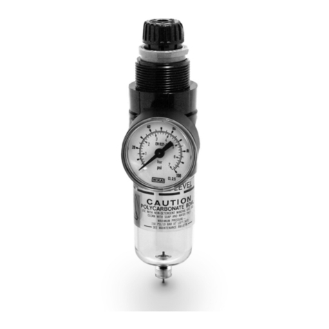
High Efficiency Compressed Air Filter / Regulator
Installation and Maintenance Instructions
IM-P054-08
CH Issue 2
0549750/2
Printed in the UK © Copyright 2001
What is the MPC2 used for?
The MPC2 is used to provide very high
quality compressed air.
There are an ever increasing number of
applications where compressed air of a
particularly high quality is required. Typical
examples include air bearings on machine
tools, air gauging equipment, instrument air
supplies, fluidic systems, breathing air,
pneumatic positioners, etc.
How efficient is the MPC2?
Spirax-Monnier coalescing filters when
tested to BS 3928 or the D.O.P. test, are
more than 99.999% efficient.
Inthesodiumflametest(BS3928)theelement
ischallengedbyacloudofsaltparticlesofmass
mean diameter of 0.6 micron. In the American
D.O.P. test, a cloud of droplets of mass mean
diameter 0.3 micron is used.
How does the MPC2 work?
These units filter out solid contaminants
and remove oil and water liquids and
aerosols, by coalescing.
Contaminated air flows to the inside of the
filter cartridge. The cartridge contains a
labyrinth of micro fibres which will trap solid
particles down to sub micron size. Fine liquid
mist and aerosols on their journey through
the depth of the element, will strike one or
other of the fibres and will be retained on
them by inter-molecular forces.
As the droplets migrate through the element
due to the air flow, they will join (coalesce)
with others, growing in size. A specially
designed porous plastic sock forms the outer
layer of the filter cartridge. This encourages
furthercoalescing,sothatthedropletmass is
sufficienttoallowittogravitatetothesumpof
the filter from which they can be drained
manually. The porous plastic sock also
reduces the possibility of re-entrainment.
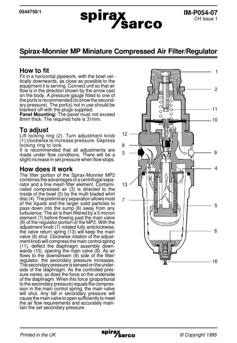
With the adjustment knob (1) rotated fully
anticlockwise, the valve return spring (13) will
keepthemainvalve(8)shut.Clockwiserotation
of the adjustment knob will compress the main
control spring (11), deflect the diaphragm
assembly downwards (10), opening the main
valve (8). As air flows to the downstream (9)
side of the filter/regulator, the secondary
pressureincreases.The secondary pressureis
sensed on the underside of the diaphragm. As
the controlled pressure varies, so does the
forceontheundersideof the diaphragm. When
this force (proportional to the secondary
pressure) equals the compression in the main
control spring, the main valve will shut. Any fall
insecondarypressurewillcausethemainvalve
to open sufficiently to meet the air flow
requirements and maintain the set secondary
pressure.
Anyappreciablerisein the secondary pressure
from its set value will cause the diaphragm and
the push rod (12) to lift. This will allow air to
escape through the centre of the push rod to
atmosphere.Whenexcesspressurehasvented,
theorificeinthepushrodwillreseatonthemain
valve.
Ensure that the bowl is regularly drained by
means of the quick action drain valve (16).
11
12
13
1
2
10
8
9
16
17
Tamper
proof cap
IM-P054-08 CH Issue 2
General safety, installation and maintenance guidelines
WARNING
As with all pressurised systems, do not attempt any installation or maintenance
function if there is any pressure in the product or connected system.
Spirax-Monnier
Spirax-Monniercompressedairproductsareofwellprovenandsimple design, with high natural
levels of designed safety built-in. However, used or installed incorrectly, their performance and
that of the system they are protecting or controlling, may suffer. The information given in this
document indicates the product limiting conditions, maintenance and installation requirements
and any specific component disposal needs (see Table opposite).
Note
Customers are reminded that under UK and EC Health, Safety and Environmental Law,
when returning products to Spirax Sarco they must provide information on any hazards
and the precautions to be taken due to contamination residues or mechanical damage
which may present a health, safety or environmental risk. This information must be
provided in writing including Health and Safety data sheets relating to any substances
identified as hazardous.
Installation and operation
1. Filters, filter/regulators, lubricators, flowmeters, separators and drain traps should be
fitted in horizontal pipelines, with the bowls vertically downwards.
2. Regulators and ball valves can be installed in any position.
3. On pressure regulators and combined filter/regulators, a pressure gauge can be connected
to one of the 1/8" ports. The gauge should be selected to cover the maximum pressure range
of the main control spring. The gauge will indicate the downstream or controlled pressure.
4. Ensure that the control spring range for regulators and filter/regulators fully meets the
pressure requirements of the system.
5. There are maximum operating pressures, and maximum operating and environmental
temperatures for each product. These are shown in the Table opposite.
6. Adequate space should be provided around any product to allow easy access for routine
servicing requirements.
7. Products fitted with a bowl (polycarbonate or metal ) should be adequately drained - manually
or automatically - to reduce the potentially harmful effects of water carryover.
8. WARNING Polycarbonate bowls and sight domes, and sight levels fitted to metal bowls,
may be attacked by phosphate ester based fluids, solvents, chemical cleaners, carbon
tetrachloride, etc. These and other similar substances should never be allowed to come into
contact with these product components. Certain compressor lubricating oils also contain
additives harmful to these components. Where there is any doubt, we recommend, in the
interests of safety, that bowl guards or metal bowls are fitted.
9. Local regulations may restrict the use of this product below the conditions quoted.
10. For more detailed information on any individual product, please ask for the appropriate
Technical Information Sheet listed in the Table opposite.
IM-P054-08 CH Issue 2
Metal bowl with *Technical
Polycarbonate bowl Metal bowl sight level Disposal Information
Sheet
Filters bar °C bar °C bar °C Class TI-
MF2 10 50 17 80 - - 1 and 3 P050-05
IF2/D/A 10 50 17 80 17 70 1 and 2 P500-01
IC3/4/DA 10 50 17 80 17 70 1 and 2 P501-01
IXI 10 50 17 70 17 70 1 and 2 P057-01
SF3/A - - 17 80 17 70 1 and 3 P050-03
Regulators
MR1/2/3 21 bar @ 70°C : Control ranges : 0.2 - 2, 0.3 - 4, 0.7 - 9 bar 1 and 3 P051-01
IRI 20 bar @ 70°C : Control ranges : 0.2 - 3.5, 0.5 - 10 bar 1 and 2 P058-01
SR2 21 bar @ 70°C : Control ranges : 1.3 - 17.0 bar 1 and 3 P570-01
SR3 21 bar @ 70°C : Control ranges : 0.2 - 4, 0.3 - 9 bar 1 and 3 P570-03
Filter regulators
IP2/A/D 10 50 17 80 17 70 1 and 2 P510-01
Ranges : 0.2 - 3.5, 0.5 - 10 bar
MP2 10 50 17 80 - - 1 and 3 P054-01
Ranges : 0.2 - 2.0, 0.3 - 4.0, 0.7 - 9.0 bar
MPC2 10 50 17 80 - - 1 and 3 P054-04
Ranges : 0.2 - 2.0, 0.3 - 4.0, 0.7 - 9.0 bar
Lubricators
ML3 10 50 17 80 - - 1 and 3 P052-07
IL1 10 50 17 80 17 70 1 and 2 P059-01
SL3 - - 17 80 17 70 1 and 3 P052-04
Other products
IFM2 10 50 - - - - 1 and 2 P580-01
S.M.S. - - 17 70 - - 1 and 3 P050-17
All ball All to 15 bar and 45°C
valves (see performance graph on TI for full details) 1 and 4 P560-01
Dri-line - - 16 80 - - 1 and 3 P050-07
*Disposal classes
1. Some plastic and/or rubber components
2. Main body zinc - epoxy coated
3. Main body aluminium - epoxy coated
4. Brass and steel
5. Electronic components
Maximum pressures / temperatures
IM-P054-08 CH Issue 2
00
50
2
4
6
8
10
bar
Important installation notes:
1. Coalescing filters should be installed as
close as possible to the equipment they
are protecting.
2. Do not exceed the maximum flowrate (for
any given pressure) as shown on the graph
(see TI-P054-05) or there is every chance
that some of the coalesced liquids will be
re-entrained and carried on downstream.
3. Do not overload the filter cartridge or there
will be a reduction in its efficiency and/or
life. On heavily contaminated systems, it
is advisable to fit a conventional pneumatic
filter(InternationalorMiniature) immediately
in front of the coalescing filter for maximum
efficiency and life.
Commissioning
How to adjust the MPC2:
If a locking seal (17) is fitted, remove it to
readjustthepressureasrequired.Liftthelocking
ring(2).Turntheadjustmentknob(1)clockwise
to increase the pressure. Depress the locking
ring to lock.
Note: A metal tamper proof cap may be fitted
over the adjustment housing.
It is recommended that all adjustments are
made under flow conditions.
There will be a slight increase in set pressure
when flow stops.
Spare parts
The spare parts available are detailed below.
No other parts are supplied as spares.
Available spares
Polycarbonate bowl / metal bowl /
drain assembly A, B
(specify with or without drain)
Element and 'O' ring set B, C, D
Bowl guard assembly X, Y, Z
Note: In the interest of safety Spirax Sarco
recommend that a bowl guard (an optional
extra) should be fitted. See point 8 of
'Installation and operation'.
How to order spares
Always order spares by using the description
giveninthecolumnhead'Availablespares'and
state the size and type of unit.
Example: 1 off Element and 'O' ring set for ¼"
Spirax-Monnier MPC2 high filter compressed
air filter/regulator.
X
Optional extra
Bowl guard
Optional extra
Tamper
proof cap
Optional extra
Locking seal
D
C
Y
16
1
B
A
Z
Optional extra
* Mounting ring
Optional
extra
Type 8
mounting
bracket
Optional extra
Pressure gauge
Optional extra
Metal bowl
*
*How to service the filter
Shut off the main air supply. Remove the bowl
guardiffitted.Releasethepressure by turning
the main control knob (1) fully anticlockwise,
and depressing the drain valve (16). Remove
the bowl and unscrew the element assembly.
Clean the bowl using soap and water and dry
with a clean lint free cloth. Reassemble in
reverse order, ensuring that the element 'O'
ring is fitted. The bowl should be firmly hand
tightened.
For more detailed information regarding
optional extras see TI-P054-05.

Other Spirax Sarco Controllers manuals

Spirax Sarco SP500 User manual

Spirax Sarco

Spirax Sarco SP500 User manual

Spirax Sarco MPC1 User manual

Spirax Sarco

Spirax Sarco MPC1 User manual

Spirax Sarco 3000 Series User manual

Spirax Sarco

Spirax Sarco 3000 Series User manual

Spirax Sarco SX80 User manual

Spirax Sarco

Spirax Sarco SX80 User manual

Spirax Sarco SX Series User manual

Spirax Sarco

Spirax Sarco SX Series User manual

Spirax Sarco AEL8 Series User manual

Spirax Sarco

Spirax Sarco AEL8 Series User manual

Spirax Sarco LC1350 User manual

Spirax Sarco

Spirax Sarco LC1350 User manual

Spirax Sarco 25T User manual

Spirax Sarco

Spirax Sarco 25T User manual

Spirax Sarco AEL7 Series User manual

Spirax Sarco

Spirax Sarco AEL7 Series User manual

Spirax Sarco IP2AM User manual

Spirax Sarco

Spirax Sarco IP2AM User manual

Spirax Sarco TN2000RH User manual

Spirax Sarco

Spirax Sarco TN2000RH User manual

Spirax Sarco X5 User manual

Spirax Sarco

Spirax Sarco X5 User manual

Spirax Sarco LCR2250 User manual

Spirax Sarco

Spirax Sarco LCR2250 User manual

Spirax Sarco SX100 Specification sheet

Spirax Sarco

Spirax Sarco SX100 Specification sheet

Spirax Sarco LC2500 User manual

Spirax Sarco

Spirax Sarco LC2500 User manual

Spirax Sarco AEL3 Series User manual

Spirax Sarco

Spirax Sarco AEL3 Series User manual

Spirax Sarco 600 Series User manual

Spirax Sarco

Spirax Sarco 600 Series User manual

Spirax Sarco LC2650 User manual

Spirax Sarco

Spirax Sarco LC2650 User manual

Spirax Sarco AEL5 Series User manual

Spirax Sarco

Spirax Sarco AEL5 Series User manual

Spirax Sarco PN9120 User manual

Spirax Sarco

Spirax Sarco PN9120 User manual

Spirax Sarco 1600V User manual

Spirax Sarco

Spirax Sarco 1600V User manual

Spirax Sarco SX25 Series User manual

Spirax Sarco

Spirax Sarco SX25 Series User manual

Spirax Sarco LC2400 User manual

Spirax Sarco

Spirax Sarco LC2400 User manual

Spirax Sarco PN 3000 Series User manual

Spirax Sarco

Spirax Sarco PN 3000 Series User manual

Popular Controllers manuals by other brands

Extron electronics VNM EC 201 Setup guide

Extron electronics

Extron electronics VNM EC 201 Setup guide

Alesis Vortex user guide

Alesis

Alesis Vortex user guide

Asco 342 Series Installation & maintenance instructions

Asco

Asco 342 Series Installation & maintenance instructions

Asparion D700 manual

Asparion

Asparion D700 manual

StarTech.com PEXSAT2IDE2 user guide

StarTech.com

StarTech.com PEXSAT2IDE2 user guide

Allen-Bradley 1305 Series user manual

Allen-Bradley

Allen-Bradley 1305 Series user manual

tiny controls TNC-G13 Operation manual

tiny controls

tiny controls TNC-G13 Operation manual

Universal Devices ISY-994i Series user manual

Universal Devices

Universal Devices ISY-994i Series user manual

Kenwood KCA-CM50 instruction manual

Kenwood

Kenwood KCA-CM50 instruction manual

Taco Electronic Solutions iWorx HPU2 installation guide

Taco Electronic Solutions

Taco Electronic Solutions iWorx HPU2 installation guide

SOMFY animeo KNX 4 installation guide

SOMFY

SOMFY animeo KNX 4 installation guide

Siemens SIMATIC 500 user manual

Siemens

Siemens SIMATIC 500 user manual

EAS Electric EMCH R32 Series operating manual

EAS Electric

EAS Electric EMCH R32 Series operating manual

Enerdrive ePOWER EN43020 owner's manual

Enerdrive

Enerdrive ePOWER EN43020 owner's manual

Unitronics Vision OPLC V1040-T20B user guide

Unitronics

Unitronics Vision OPLC V1040-T20B user guide

AGS Merlin 500S user guide

AGS

AGS Merlin 500S user guide

GJD SAPPHIRE MK3 installation manual

GJD

GJD SAPPHIRE MK3 installation manual

Okina OK-PTZ-KB300 user manual

Okina

Okina OK-PTZ-KB300 user manual

manuals.online logo
manuals.online logoBrands
  • About & Mission
  • Contact us
  • Privacy Policy
  • Terms and Conditions

Copyright 2025 Manuals.Online. All Rights Reserved.