Geokon 4430 User manual

Instruction Manual
Model 4430
VW Deformation Meter
No part of this instruction manual may be reproduced, by any means, without the written consent of Geokon®.
The information contained herein is believed to be accurate and reliable. However, Geokon®assumes no responsibility for errors,
omissions or misinterpretation. The information herein is subject to change without notification.
Copyright © 1988-2019 by Geokon®
(Doc Rev L, 1/09/2019)


Warranty Statement
Geokon warrants its products to be free of defects in materials and workmanship, under normal
use and service for a period of 13 months from date of purchase. If the unit should malfunction,
it must be returned to the factory for evaluation, freight prepaid. Upon examination by Geokon,
if the unit is found to be defective, it will be repaired or replaced at no charge. However, the
WARRANTY is VOID if the unit shows evidence of having been tampered with or shows
evidence of being damaged as a result of excessive corrosion or current, heat, moisture or
vibration, improper specification, misapplication, misuse or other operating conditions outside of
Geokon's control. Components which wear or which are damaged by misuse are not warranted.
This includes fuses and batteries.
Geokon manufactures scientific instruments whose misuse is potentially dangerous. The
instruments are intended to be installed and used only by qualified personnel. There are no
warranties except as stated herein. There are no other warranties, expressed or implied, including
but not limited to the implied warranties of merchantability and of fitness for a particular
purpose. Geokon is not responsible for any damages or losses caused to other equipment,
whether direct, indirect, incidental, special or consequential which the purchaser may experience
as a result of the installation or use of the product. The buyer's sole remedy for any breach of this
agreement by Geokon or any breach of any warranty by Geokon shall not exceed the purchase
price paid by the purchaser to Geokon for the unit or units, or equipment directly affected by
such breach. Under no circumstances will Geokon reimburse the claimant for loss incurred in
removing and/or reinstalling equipment.
Every precaution for accuracy has been taken in the preparation of manuals and/or software,
however, Geokon neither assumes responsibility for any omissions or errors that may appear nor
assumes liability for any damages or losses that result from the use of the products in accordance
with the information contained in the manual or software.


TABLE of CONTENTS
1. INTRODUCTION ...................................................................................................................................................1
1.1 THEORY OF OPERATION.......................................................................................................................................1
2. INSTALLATION ....................................................................................................................................................2
2.1 PRELIMINARY TESTS............................................................................................................................................2
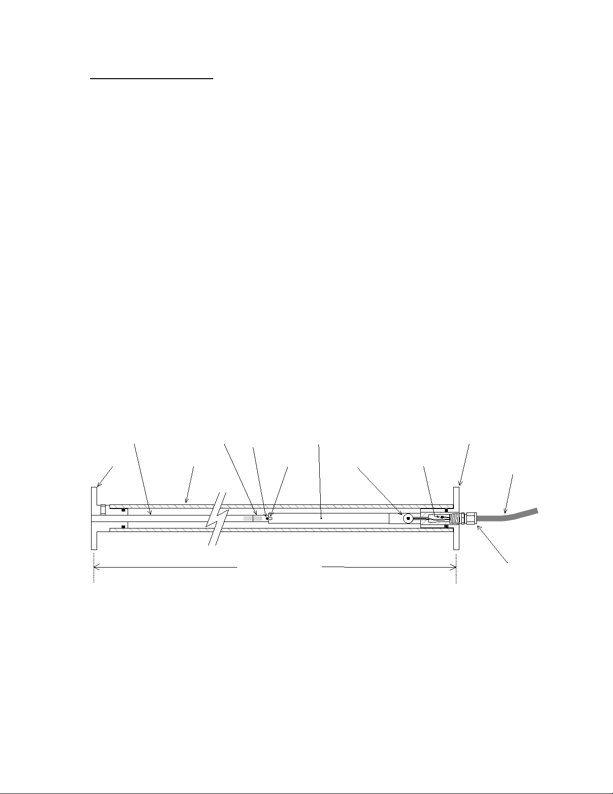
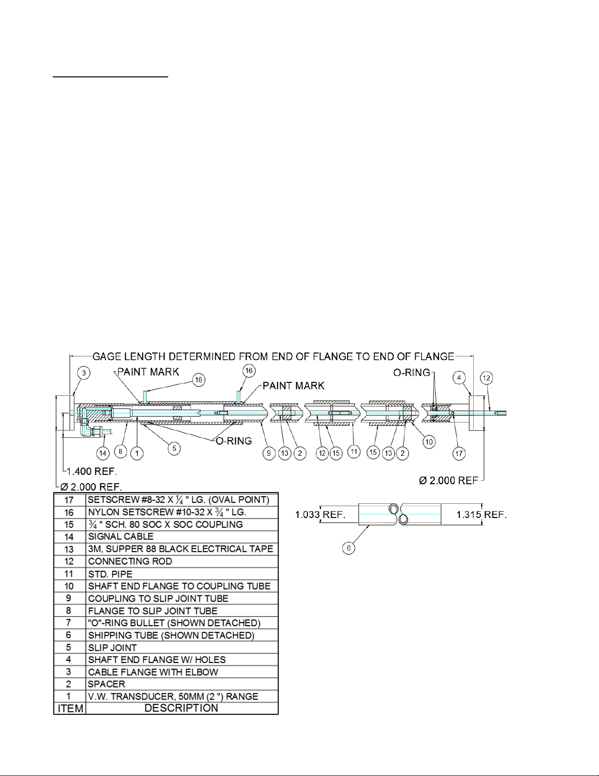
2.2 SENSOR ASSEMBLY ..............................................................................................................................................2
2.3 DEFORMATION METER INSTALLATION ................................................................................................................4
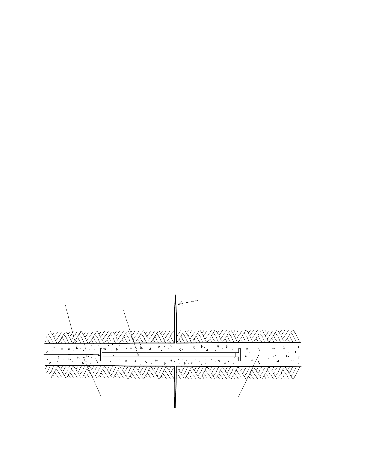
2.3.1 Installation in Boreholes.............................................................................................................................4
2.3.2 Installation in Mass Concrete .....................................................................................................................5
2.3.3 Installation in Fills and Embankments – Soil Strain Gauges......................................................................5
2.4 CABLE INSTALLATION AND SPLICING ..................................................................................................................6
2.5 INITIAL READINGS ...............................................................................................................................................6
2.6 ELECTRICAL NOISE..............................................................................................................................................6
2.7 LIGHTNING PROTECTION .....................................................................................................................................7
3. TAKING READINGS.............................................................................................................................................8
3.1 GK-404 READOUT BOX.......................................................................................................................................8
3.1.1 Operating the GK-404 ................................................................................................................................8
3.2 GK-405 READOUT BOX.......................................................................................................................................9
3.2.1 Connecting Sensors with 10-pin Bulkhead Connectors Attached ...............................................................9
3.2.2 Connecting Sensors with Bare Leads..........................................................................................................9
3.2.3 Operating the GK-405 ................................................................................................................................9
3.3 GK-403 READOUT BOX (OBSOLETE MODEL)....................................................................................................10
3.3.1 Connecting Sensors with 10-pin Bulkhead Connectors Attached .............................................................10
3.3.2 Connecting Sensors with Bare Leads........................................................................................................10
3.3.3 Operating the GK-403 ..............................................................................................................................10
3.4 MEASURING TEMPERATURES.............................................................................................................................10
4. DATA REDUCTION ............................................................................................................................................11
4.1 DEFORMATION CALCULATION...........................................................................................................................11
4.2 TEMPERATURE CORRECTION .............................................................................................................................13
4.3ENVIRONMENTAL FACTORS ...............................................................................................................................14
5. TROUBLESHOOTING........................................................................................................................................15
APPENDIX A. SPECIFICATIONS.........................................................................................................................17
A.1 MODEL 4430 DEFORMATION METER ................................................................................................................17
A.2 THERMISTOR (SEE APPENDIX BALSO) ..............................................................................................................17
APPENDIX B. THERMISTOR TEMPERATURE DERIVATION.....................................................................18

FIGURES
FIGURE 1-MODEL 4430 DEFORMATION METER ........................................................................................................... 1
FIGURE 2-4435 PRINT .................................................................................................................................................. 2
FIGURE 3-O-RING BULLET ........................................................................................................................................... 3
FIGURE 4-BOREHOLE INSTALLATION ........................................................................................................................... 4
FIGURE 5-INSTALLATION ALONG CREST OF DAM ........................................................................................................ 5
FIGURE 6-BOREHOLE INSTALLATION IN EMBANKMENT............................................................................................... 5
FIGURE 7-LIGHTNING PROTECTION SCHEME ............................................................................................................... 7
FIGURE 8-LEMO CONNECTOR TO GK-404 ................................................................................................................... 8
FIGURE 9-LIVE READINGS –RAW READINGS............................................................................................................... 9
FIGURE 10 -ATYPICAL CALIBRATION SHEET ..............................................................................................................12
TABLES
TABLE 1-ENGINEERING UNITS CONVERSION MULTIPLIERS ........................................................................................11
TABLE 2-THERMAL COEFFICIENT CALCULATION CONSTANTS ...................................................................................13
TABLE 3-SAMPLE RESISTANCE ...................................................................................................................................16
TABLE 4-RESISTANCE WORK SHEET...........................................................................................................................16
TABLE 5-MODEL 4430 SPECIFICATIONS......................................................................................................................17
TABLE 6-THERMISTOR RESISTANCE VERSUS TEMPERATURE ......................................................................................18
EQUATIONS
EQUATION 1-DIGITS CALCULATION............................................................................................................................11
EQUATION 2-DEFORMATION CALCULATION ...............................................................................................................11
EQUATION 3-THERMALLY CORRECTED DEFORMATION CALCULATION ......................................................................13
EQUATION 4-THERMAL COEFFICIENT CALCULATION .................................................................................................13
EQUATION 5-GAUGE LENGTH CORRECTION ...............................................................................................................14
EQUATION 6-RESISTANCE TO TEMPERATURE .............................................................................................................18

1
1. INTRODUCTION
1.1 Theory of Operation
The Geokon Model 4430 Vibrating Wire Deformation Meter is designed to measure axial
deformations in boreholes in rock, concrete or soil. It can also be embedded in soils in
embankments such as earth dams and highway fills. The units can be installed in series providing
incremental deformation measurements over any length. Base lengths of the gauge can vary from
a minimum of one meter to over 25 meters.
The basic sensing element is a vibrating wire strain gauge in series with a precision music wire
spring that is coupled to a movable shaft. As the shaft moves in or out of the sensor body, the
tension changes in the spring as well as the vibrating wire element. This change in tension is
directly proportional to the amount of extension and, through calibration, a calibration factor that
relates the frequency of vibration to the amount of extension is determined. The unit is stress
relieved after manufacture providing for excellent stability over long periods of time.
The gauge sensor is attached to a flange at one end and by a connecting rod of some length to a
flange at the other end. The sensor and the rod are covered by a plastic (PVC) tube which holds
the end flanges apart at a predetermined distance (gauge length), and insures that the rod is free
to move. As the flanges move apart, the movement is conveyed by the connecting rod to the
sensor and measured by the readout system. Different combinations of gauge length and sensor
range provide for optimum sensitivity. For maximum strain resolution, a long base gauge with a
short range transducer will give best results. For maximum deformation: short base length,
longer transducer range. The flexibility of the system allows the user to choose the most useful
combination of range and sensitivity according to predicted movements.
Nominal Gage Length
(1m, 39")
End Flange
Swagelok Fitting
Instrument Cable
End Flange
Electromagnetic Coils Thermistor
(4 conductor, 22 AWG)
PVC Outer Tube
Transducer Shaft HousingAlignment Pin
Alignment Slot
Extension Rod Transducer Shaft
Figure 1 - Model 4430 Deformation Meter
Readouts available from Geokon, used in conjunction with the Vibrating Wire Deformation
Meter, will provide the necessary voltage pulses to pluck the wire and convert the measured
frequencies to display the reading.

2
2. INSTALLATION
2.1 Preliminary Tests
Upon receipt of the instrument, the gauge should be checked for proper operation (including the
thermistor). In position "B" the gauge will read between 2000 and 8000 digits (see Section 3 for
readout instructions). When pulling slightly on the end flanges (items number three and four in
Figure 2), the reading should increase.
Checks of electrical continuity can also be made using an ohmmeter. Resistance between the
gauge leads should be approximately 180Ω, ±10Ω. Remember to add cable resistance when
checking. (22 AWG stranded copper leads have a resistance of approximately 14.7Ωper 1000
feet or 48.5Ωper kilometer. Multiply these factors by two to account for both directions.)
Resistance between the green and white conductors should be approximately 3000 ohms at 25 °C
(see Table 6 in Appendix B for other temperatures), and between any conductor and the shield
should exceed two megohms.
2.2 Sensor assembly
Figure 2 - 4435 Print

3
Complete the following:
(Item numbers referenced in the following steps are detailed in Figure 2.)
1) Remove the 1.315” shipping tube (Item 6) from the back of the transducer and discard. At
this point, the shipping spacer, or shipping pin, can be removed and the push rod can be
gently retracted back into the transducer. Perform preliminary tests on the sensors to verify
proper operation (Section 2.1).
2) Install a length of flush-coupled connecting rod (Item 12) into the threaded rod of the
transducer. Use a thread locker if available. Caution: When threading the connecting rod into
the push rod of the transducer, ensure the pin of the pushrod is fully engauged in the slot of
the transducer tube to prevent rotation of internal components.
3) Slide the slip joint (Item 5) over the connecting rod and transducer until the end aligns with
the paint mark located on the flange to slip joint tube (Item 8). Tighten the nylon set screws
(Item 16) to maintain this position.
4) Spacers (Item 2) should be installed along the connecting rod at 3' (one meter) intervals to
prevent the rod from flexing in the tube. This is done by locating the spacer in its
approximate location and wrapping tape around the connecting rod on both sides of the
spacer using the provided electrical tape (Item 13).
5) Install the coupling to slip joint tube (Item 9) into the slip joint until the painted mark aligns
with the other side of the slip joint and tighten the nylon set screws (Item 16). Note:
Depending on the gauge length, this tube may couple directly to the shaft end flange (Item 4).
6) For longer gauge lengths, couplings and standard pipes are provided. Use PVC cement to
affix a coupling (Item 15) to the slip joint to coupling tube. On the other side of the coupling,
cement a length of standard pipe (Item 11). Continue to add couplings, tubes, spacers, and
connecting rod until there is only the shaft end flange to connect.
7) Attach the provided o-ring bullet (Item 7) to the final length of connecting rod. This will
allow the shaft end flange to be slid over the connecting rod without damaging the internal o-
rings. PVC cement the shaft end flange to coupling tube (Item 10) to the final coupling. The
o-ring bullet can now be removed and used with other assemblies.
Figure 3 - O-ring Bullet
8) At this point, the gauge length should be established. If minor adjustments are needed, the
nylon set screws in the slip joint can be loosened and either end adjusted to the proper
distance. Note: The assembly should only be adjusted by half the range of the sensor in either
direction from the painted mark.

4
9) To set the range of the transducer, take the end of the connecting rod (Item 12) protruding
out the back of the flange and pull it to the desired percentage of the range, either by
measuring the distance the rod was pulled, or by recording the reading of the sensor while
pulling on the connecting rod (preferred method). Make sure not to overextend the rod or
rotate it beyond 180 degrees as this may damage the sensor. Tighten the setscrews (Item 17)
in the rod end flange to lock the sensor's position in place. Any excess rod protruding out of
the back can be sawed off at this point, if needed.
10) Install the assembly, and then loosen the nylon setscrews. Take baseline zero readings for
comparison.
2.3 Deformation Meter Installation
2.3.1 Installation in Boreholes
The primary use of the Model 4430 is for the measurement of axial strains or
deformations in boreholes. The most common method of installation is by grouting.
Horizontal holes should be inclined slightly downward to make for easy grouting and to
avoid air pockets. Vertical up holes require special grouting apparatus and snap ring or
hydraulic anchors on the gauge to hold it in place while grouting the hole.
Horizontal and vertical down holes are instrumented as follows:
Drill the borehole at least 0.5 meters (≈two feet) beyond the location of the deepest
flange. The borehole must be a minimum of 60 mm (2.25") in diameter. Fill the hole with
grout mixture of one part Portland cement to one to two parts water by volume. An
expansive mix is helpful particularly in horizontal holes. Lower or push the sensor(s)
down the hole to the proper location as noted by a mark on the cable. If more than one
sensor is to be placed in a hole, be sure to maintain the position of the lower sensor while
installing shallower ones.
Grout
Instrument Cable
Deformation Meter
Fault
Borehole
Figure 4 - Borehole Installation
For situations such as soft ground or when the hole is cased and casing must be
withdrawn, it may be advisable to use a sensor with a hydraulic anchor for permanent
positioning. This should be discussed with the application engineers at the factory.

5
2.3.2 Installation in Mass Concrete
The Model 4430 can be placed directly into concrete or prewired into the rebar cage or
network prior to concrete placement. Tie wires should be connected to the tube rather
than the end blocks and should be perpendicular to the tube and not excessively tight to
allow for shifting during placement of the concrete. The unit has a compressive modulus
of approximately 200,000 psi, and should follow the concrete at very early stages of
curing.
2.3.3 Installation in Fills and Embankments – Soil Strain Gauges
(For more details, see the Model 4435 Soil Strainmeter Manual)
The Model 4435, which is a variation of the Model 4430, is used as a soil deformation
meter in fills and embankments by placing the unit in shallow, horizontal trenches in the
fill. Multiple sensors can be installed in series to give a total deformation profile along a
particular axis as in a dam or highway embankment. Cables issue out of the side of the
devise so that the flanges can be linked together easily.
Downstream
Deformation Meters
Reservoir
Figure 5 - Installation Along Crest of Dam
A narrow flat bottom trench should be excavated in previously compacted fill. The sensor
is laid in the trench and backfilled with material which has had any large (>10 mm, 0.5")
aggregate removed. Backfill and hand tamp the first 15 cm (≈6") and then proceed with
the compaction of the fill in the normal way. Cables should also be run in trenches and
backfilled in the same manner as above. For more details, consult the Model 4435 Soil
Strainmeter manual.
Embankment Face
Shear Zone
Horizontal Borehole
Deformation Meters
Figure 6 - Borehole Installation in Embankment

6
2.4 Cable Installation and Splicing
The cable should be routed to minimize the possibility of damage due to moving equipment,
debris or other causes. The cable can be protected by the use of flexible conduit, which can be
supplied by Geokon.
Terminal boxes with sealed cable entries are available from Geokon for all types of applications.
These allow many gauges to be terminated at one location with complete protection of the lead
wires. The interior panel of the terminal box can have built-in jacks or a single connection with a
rotary position selector switch. Contact Geokon for specific application information.
Because the vibrating wire output signal is a frequency rather than a current or voltage,
variations in cable resistance have little effect on gauge readings; therefore, splicing of cables
has no ill effects, and in some cases may in fact be beneficial. The cable used for making splices
should be a high quality twisted pair type, with 100% shielding and an integral shield drain wire.
When splicing, it is very important that the shield drain wires be spliced together. Always
maintain polarity by connecting color to color.
Splice kits recommended by Geokon incorporate casts, which are placed around the splice and
are then filled with epoxy to waterproof the connections. When properly made, this type of splice
is equal or superior to the cable in strength and electrical properties. Contact Geokon for splicing
materials and additional cable splicing instructions.
Cables may be terminated by stripping and tinning the individual conductors and then connecting
them to the patch cord of a readout box. Alternatively, a connector may be used which will plug
directly into the readout box or to a receptacle on a special patch cord.
2.5 Initial Readings
All readings are referred to an initial reading so it is important that this initial reading be
carefully taken. Conditions should be noted at the time of all readings, especially during curing,
e.g., temperature, time after placement, local conditions, etc.
2.6 Electrical Noise
Care should be exercised when installing instrument cables to keep them as far away as possible
from sources of electrical interference such as power lines, generators, motors, transformers, arc
welders, etc. Cables should never be buried or run with AC power lines! The instrument
cables will pick up the 50 or 60 Hz (or other frequency) noise from the power cable and this will
likely cause a problem obtaining a stable reading.

7
2.7 Lightning Protection
The Model 4430 Vibrating Wire Deformation Meter, unlike numerous other types of
instrumentation available from Geokon, does not have any integral lightning protection
components, i.e., transzorbs or plasma surge arrestors. Usually this is not a problem however, if
the instrument cable is exposed, it may be appropriate to install lightning protection components,
as the transient could travel down the cable to the deformation meter and possibly destroy it.
Note the following suggestions:
•If the gauge is connected to a terminal box or multiplexer components such as plasma surge
arrestors (spark gaps) may be installed in the terminal box/multiplexer to provide a measure
of transient protection. Terminal boxes and multiplexers available from Geokon provide
locations for installation of these components.
•Lighting arrestor boards and enclosures are available from Geokon that install near the
instrument. The enclosure has a removable top. If the protection board (LAB-3) is damaged,
the user may service the components (or replace the board). A connection is made between
this enclosure and earth ground to facilitate the passing of transients away from the gauge.
See Figure 7. Consult the factory for additional information on these or alternate lightning
protection schemes.
•Plasma surge arrestors can be epoxy potted into the gauge cable close to the sensor. A ground
strap would connect the surge arrestor to earth ground; either a grounding stake or other
suitable earth ground.
Terminal Box/Multiplexer
Instrument Cable
LAB-3 Enclosure LAB-3 Board
Deformation Meter
Ground Connections
Surface
(usually buried)
Figure 7 - Lightning Protection Scheme

8
3. TAKING READINGS
3.1 GK-404 Readout Box
The Model GK-404 Vibrating Wire Readout is a portable, low-power, handheld unit that is
capable of running for more than 20 hours continuously on two AA batteries. It is designed for
the readout of all Geokon vibrating wire gauges and transducers, and is capable of displaying the
reading in either digits, frequency (Hz), period (µs), or microstrain (µε). The GK-404 also
displays the temperature of the transducer (embedded thermistor) with a resolution of 0.1 °C.
3.1.1 Operating the GK-404
Before use, attach the flying leads to the GK-404 by aligning the red circle on the silver
“Lemo” connector of the flying leads with the red line on the top of the GK-404 (Figure
8). Insert the Lemo connector into the GK-404 until it locks into place.
Figure 8 - Lemo Connector to GK-404
Connect each of the clips on the leads to the matching colors of the sensor conductors,
with blue representing the shield (bare).
To turn the GK-404 on, press the “ON/OFF” button on the front panel of the unit. The
initial startup screen will be displayed.
After approximately one second, the GK-404 will start taking readings and display them
based on the settings of the POS and MODE buttons.
The unit display (from left to right) is as follows:
•The current Position: Set by the POS button. Displayed as a letter A through F.
•The current Reading: Set by the MODE button. Displayed as a numeric value
followed by the unit of measure.
•Temperature reading of the attached gauge in degrees Celsius.
Use the POS button to select position Band the MODE button to select Dg (digits).
(Other functions can be selected as described in the GK-404 Manual.)
The GK-404 will continue to take measurements and display readings until the unit is
turned off, either manually, or if enabled, by the Auto-Off timer. If the no reading
displays or the reading is unstable, see Section 5 for troubleshooting suggestions.
For further information, please refer to the GK-404 manual.

9
3.2 GK-405 Readout Box
The GK-405 Vibrating Wire Readout is made up of two components: The Readout Unit,
consisting of a Windows Mobile handheld PC running the GK-405 Vibrating Wire Readout
Application; and the GK-405 Remote Module, which is housed in a weatherproof enclosure and
connects to the vibrating wire gauge to be measured. The two components communicate
wirelessly using Bluetooth®, a reliable digital communications protocol. The Readout Unit can
operate from the cradle of the Remote Module, or, if more convenient, can be removed and
operated up to 20 meters from the Remote Module.
3.2.1 Connecting Sensors with 10-pin Bulkhead Connectors Attached
Align the grooves on the sensor connector (male), with the appropriate connector on the
readout (female connector labeled senor or load cell). Push the connector into place, and
then twist the outer ring of the male connector until it locks into place.
3.2.2 Connecting Sensors with Bare Leads
Attach the GK-403-2 flying leads to the bare leads of a Geokon vibrating wire sensor by
connecting each of the clips on the leads to the matching colors of the sensor conductors,
with blue representing the shield (bare).
3.2.3 Operating the GK-405
Press the button labeled “POWER ON (BLUETOOTH)”. A blue light will begin
blinking, signifying that the Remote Module is waiting to connect to the handheld unit.
Launch the GK-405 VWRA program by tapping on “Start” from the handheld PC’s main
window, then “Programs” then the GK-405 VWRA icon. After a few seconds, the blue
light on the Remote Module should stop flashing and remain lit. The Live Readings
Window will be displayed on the handheld PC. Figure 9 shows a typical vibrating wire
sensor output in digits and thermistor output in degrees Celsius. If the no reading displays
or the reading is unstable, see Section 5 for troubleshooting suggestions.
For further information, consult the GK-405 Instruction Manual.
Figure 9 - Live Readings – Raw Readings

10
3.3 GK-403 Readout Box (Obsolete Model)
The GK-403 can store gauge readings and apply calibration factors to convert readings to
engineering units. The following instructions explain taking gauge measurements using Mode
"B". Consult the GK-403 Instruction Manual for additional information.
3.3.1 Connecting Sensors with 10-pin Bulkhead Connectors Attached
Align the grooves on the sensor connector (male), with the appropriate connector on the
readout (female connector labeled senor or load cell). Push the connector into place, and
then twist the outer ring of the male connector until it locks into place.
3.3.2 Connecting Sensors with Bare Leads
Attach the GK-403-2 flying leads to the bare leads of a Geokon vibrating wire sensor by
connecting each of the clips on the leads to the matching colors of the sensor conductors,
with blue representing the shield (bare).
3.3.3 Operating the GK-403
1) Turn the display selector to position "B".
2) Turn the unit on.
3) The readout will display the vibrating wire output in digits. The last digit may change
one or two digits while reading. (See Section 4 for data reduction.)
4) The thermistor reading will be displayed above the gauge reading in degrees
centigrade.
5) Press the "Store" button to record the value displayed.
If the no reading displays or the reading is unstable, see Section 5 for troubleshooting
suggestions.
The unit will automatically turn off after approximately two minutes to conserve power.
3.4 Measuring Temperatures
All vibrating wire transducers are equipped with a thermistor, which gives a varying resistance
output as the temperature changes. The white and green leads of the instrument cable are
normally connected to the internal thermistor. The GK-403, GK-404, and GK-405 readout boxes
will read the thermistor and display the temperature in degrees Celsius.
To read temperatures using an ohmmeter:
Connect an ohmmeter to the green and white leads of the cable. Look up the temperature for the
measured resistance in Appendix B, Table 6. (Since the resistance changes with temperature are
large, the effect of cable resistance is usually insignificant. For long cables a correction can be
applied, equal to approximately 14.7 Ωfor every 1000 ft., or 48.5Ωper km at 20 °C. Multiply
these factors by two to account for both directions.)

11
4. DATA REDUCTION
4.1 Deformation Calculation
The basic units utilized by Geokon for measurement and reduction of data from Vibrating Wire
Deformation Meters are "digits". The units displayed by all Readout Boxes in position "B" are
digits. Calculation of digits is based on the following equation:
Digits = 1
Period2
x 10-3 or Digits=Hz2
1000
Equation 1 - Digits Calculation
To convert digits to deformation the following equation applies:
Deformation =(Current Reading - Initial Reading) ×Calibration Factor ×Conversion Factor
Or
D = (R1- R0) ×G ×F
Equation 2 - Deformation Calculation
Where;
R1is the Current Reading.
R0is the Initial Reading usually obtained at installation (see Section 2.5).
G is the Calibration Factor, usually in terms of millimeters or inches per digit.
F is an engineering units conversion factor (optional), see Table 1.
From→
To
↓
Inches
Feet
Millimeters
Centimeter
s
Meters
Inches
1
12
0.03937
0.3937
39.37
Feet
0.0833
1
0.003281
0.03281
3.281
Millimeters
25.4
304.8
1
10
1000
Centimeters
2.54
30.48
0.10
1
100
Meters
0.0254
0.3048
0.001
0.01
1
Table 1 - Engineering Units Conversion Multipliers
For example, taken from the typical Calibration Sheet shown in Figure 10, the Initial Reading
(R0) at installation of a deformation meter with a 25 mm transducer range is 4250 digits. The
Current Reading (R1) is 6785. The Calibration Factor is 0.004457 mm/digit. The deformation
change is:
D = (6785
−
4250)
×
0.004457 = +11.4 mm
Note that increasing readings (digits) indicate increasing extension.

12
Figure 10 - A Typical Calibration Sheet

13
4.2 Temperature Correction
The Model 4430 Deformation Meter has a very small coefficient of thermal expansion; therefore,
in most cases correction is not necessary. However, if maximum accuracy is desired or the
temperature changes are extreme (>10 °C) corrections may be applied. The following equation
applies:
Dcorrected = ((R1- R0) ×G) + ((T1- T0) ×K) + LC
Equation 3 - Thermally Corrected Deformation Calculation
Where;
R1is the Current Reading.
R0is the Initial Reading.
G is the Calibration Factor.
T1is the Current Temperature.
T0is the Initial Temperature.
K is the Thermal Coefficient.
LCis the correction for the gauge length.
Tests have determined that the Thermal Coefficient, K, changes with the position of the
transducer shaft. The first step in the temperature correction process is determination of the
proper Thermal Coefficient based on the following equation:
Thermal Coefficient = ((Reading in Digits ×Multiplier) +Constant) ×Calibration Factor
Or
K = ((R1×M) +B) ×G
Equation 4 - Thermal Coefficient Calculation
See Table 2 for the Multiplier and Constant values used in Equation 4. The Multiplier (M) and
Constant (B) values vary for the stroke of the transducer used in the Deformation Meter.
Model:
4430-
3 mm
(0.125”)
4430-
12 mm
(0.5")
4430-
25 mm
(1")
4430-
50 mm
(2")
4430-
100 mm
(4”)
4430-
150 mm
(6”)
4430-
300 mm
(12”)
Multiplier (M):
0.000520
0.000375
0.000369
0.000376
0.000398
0.000384
0.000424*
Constant (B):
3.567
1.08
0.572
0.328
0.0864
-0.3482
-0.6778*
Transducer
Length (L):
267 mm
10.5”
267 mm
10.5"
267 mm
10.5"
292 mm
11.5"
393 mm
15.49”
510.5 mm
20.1”
715.2 mm
28.2”
Table 2 - Thermal Coefficient Calculation Constants
* Calculated

14
The gauge length correction (LC) is calculated using Equation 5.
LC= 17.3 ×10⁻⁶ ×L ×(T1- T0)
Equation 5 - Gauge Length Correction
Where L is the length of deformation meter in millimeters or inches, minus the transducer length
(see Table 2), in millimeters or inches, respectively.
Consider the following example using a Model 4430 Deformation Meter with a one meter gauge
length and 25 mm transducer. Taken from the calibration sheet shown in Figure 10:
R0= 4250 digits
R1= 6785 digits
T0= 10 °C
T1= 20 °C
G = 0.004457 mm/digit
K = ((6785 ×0.000369) + 0.572) ×0.004457 = 0.0137
L = 1000 - 267 = 733
LC= 17.3 ×10-6 ×733 ×(20 - 10) = 0.1268
Dcorrected = ((R1- R0) ×G) + ((T1- T0) ×K) + LC
Dcorrected = ((6785 - 4250) ×0.004457) + ((20 - 10) ×0.0137) + 0.1268
Dcorrected = (2535 ×0.004457) + (10 ×0.0137) + 0.1268
Dcorrected = 11.298 + 0.137 + 0.1268
Dcorrected = +11.56 mm
As can be seen from the above example, the corrections for temperature change are small and
can often be ignored.
4.3 Environmental Factors
Since the purpose of the Deformation Meter installation is to monitor site conditions, factors
which may affect these conditions should always be observed and recorded. Seemingly minor
effects may have a real influence on the behavior of the structure being monitored and may give
an early indication of potential problems. Some of these factors include, but are not limited to:
blasting, rainfall, tidal levels, excavation and fill levels and sequences, traffic, temperature and
barometric changes, changes in personnel, nearby construction activities, seasonal changes, etc.
Other manuals for 4430
1
Table of contents
Other Geokon Measuring Instrument manuals

Geokon
Geokon 4650 User manual

Geokon
Geokon GK-604D User manual

Geokon
Geokon 4500 Series User manual

Geokon
Geokon 4820 User manual

Geokon
Geokon 4370 User manual

Geokon
Geokon 4420 User manual

Geokon
Geokon 4500MLP User manual

Geokon
Geokon GK-604D User manual

Geokon
Geokon GK-405 User manual

Geokon
Geokon 1100 User manual