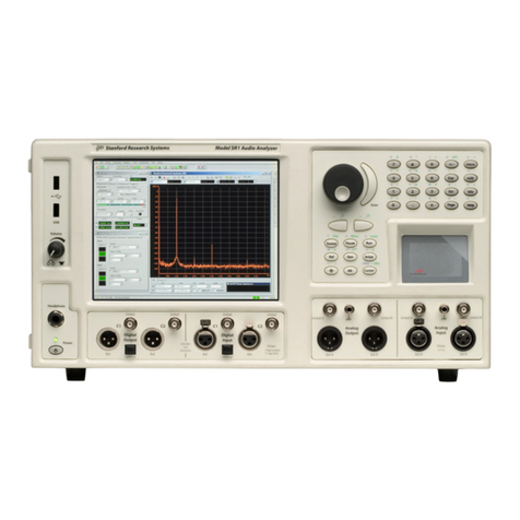
SRS Labs SR785 User manual

Revision 1.2 (October, 2004)
Service Guide
Model SR785
Dynamic Signal Analyzer
1290-D Reamwood Avenue
Sunnyvale, CA 94089 U.S.A.
Phone: (408) 744-9040 • Fax: (408) 744-9049
Copyright © 1995, 1996, 1998
Stanford Research Systems, Inc.
All Rights Reserved

SR785 Dynamic Signal Analyzer Service Guide
Certification
Stanford Research Systems certifies that this product met its published specifications at the time
of shipment. Stanford Research Systems further certifies that its calibration measurements are
traceable to the United States National Institute of Standards and Technology (NIST).
Warranty
This Stanford Research Systems product is warranted against defects in materials and
workmanship for a period of one (1) year from the date of shipment.
Service
For warranty service or repair, this product must be returned to a Stanford Research Systems
authorized service facility. Contact Stanford Research Systems or an authorized representative
before returning this product for repair.
Information in this document is subject to change without notice.
Copyright © Stanford Research Systems, Inc., 1998. All rights reserved.
Stanford Research Systems, Inc.
1290-D Reamwood Avenue
Sunnyvale, California 94089
Printed in U.S.A.

i
Service Guide SR785 Dynamic Signal Analyzer
Safety and Preparation For Use
WARNING!Dangerous voltages, capable of causing injury or death, are
present in this instrument. Use extreme caution whenever the
instrument cover is removed. Do not remove the cover while
the unit is plugged into a live outlet.
Caution This instrument may be damaged if operated with the LINE VOLTAGE SELECTOR set
for the wrong AC line voltage or if the wrong fuse is installed.
Line Voltage Selection
The SR785 operates from a 100V, 120V, 220V, or 240V nominal AC power source
having a line frequency of 50 or 60 Hz. Before connecting the power cord to a power
source, verify that the LINE VOLTAGE SELECTOR card, located in the rear panel fuse
holder, is set so that the correct AC input voltage value is visible.
Conversion to other AC input voltages requires a change in the fuse holder voltage card
position and fuse value. Disconnect the power cord, open the fuse holder cover door and
rotate the fuse-pull lever to remove the fuse. Remove the small printed circuit board and
select the operating voltage by orienting the printed circuit board so that the desired
voltage is visible when pushed firmly into its slot. Rotate the fuse-pull lever back into its
normal position and insert the correct fuse into the fuse holder.
Line Fuse Verify that the correct line fuse is installed before connecting the line cord. For
100V/120V, use a 1.5 Amp fuse. For 220V/240V, use a 3/4 Amp fuse.
Line Cord The SR785 has a detachable, three-wire power cord for connection to the power source
and to a protective ground. The exposed metal parts of the instrument are connected to
the outlet ground to protect against electrical shock. Always use an outlet which has a
properly connected protective ground.
Service Do not attempt to service or adjust this instrument unless another person, capable of
providing first aid or resuscitation, is present.
Do not install substitute parts or perform any unauthorized modifications to this
instrument. Contact the factory for instructions on how to return the instrument for
authorized service and adjustment.
Fan The fans in the SR785 are required to maintain proper operation. Do not block the vents
in the chassis or the unit may not operate properly.

ii
SR785 Dynamic Signal Analyzer Service Guide

iii
Service Guide SR785 Dynamic Signal Analyzer
Contents
Safety and Preparation For Use i
Contents iii
Table of Figures v
Chapter 1 Performance Tests
Getting Ready 1-3
Self Tests 1-7
DC Offset 1-9
Common Mode Rejection 1-11
Amplitude Accuracy 1-13
Amplitude Linearity 1-17
Anti-alias Filter Attenuation 1-19
Frequency Accuracy 1-21
Phase Accuracy 1-23
Noise and Spurious Signals 1-25
Sine Source 1-29
Harmonic Distortion 1-31
Performance Test Record 1-32
Chapter 2 Circuit Description
Overview 2-3
CPU Board 2-5
Video/IO Board 2-8
Power Supply Board 2-10
DSP Board 2-12
Analog Input Boards 2-15
Chapter 3 Service
Before Proceeding With Service 3-3
Troubleshooting Table 3-4
Circuit Board Locations 3-8
Service Procedures 3-10
Caution 3-10
Required Equipment 3-10
Power Supply Board Replacement 3-10
Power Supply Check 3-11
CRT Replacement 3-13
CRT Check 3-14
Keypad Check 3-14
Knob Check 3-15
CPU Board Replacement 3-16
Battery Check 3-17
Video/IO Board Replacement 3-17

iv Contents
SR785 Dynamic Signal Analyzer Service Guide
DSP Board Replacement 3-18
Analog Board Replacement 3-18
Checking the Analog Inputs 3-19
Checking the Amplitude 3-20
Checking the Trigger 3-20
Checking the Source 3-21
DSP Memory Module Replacement 3-21
Replacing the Disk Drive 3-22
Adjusting the DC Offset and CMR 3-24
Chapter 4 Parts List
CPU Board 4-3
Video/IO Board 4-6
Power Supply Board 4-9
System Backplane 4-11
Disk Card 4-12
DSP Board 4-13
Analog Input Board 4-20
Analyzer Backplane 4-29
Chapter 5 Schematic Diagrams
Schematic Diagram List 5-3
CPU Board MCPU-1
Video/IO Board MVID-1
Power Supply Board MPWR-1
System Backplane MBKPL-1
Disk Card MBKPL-24
Keypad Board MKEY-1
DSP Board D785-1
Analog Input Board A780-1
Analyzer Backplane M780-1
Demo Filter F780-1

v
Service Guide SR785 Dynamic Signal Analyzer
Table of Figures
Figure 3-1 System Components 3-3
Figure 3-2 Analyzer Components 3-4
Figure 3-1 System Components 3-8
Figure 3-2 Analyzer Components 3-9
Figure 3-3 Analog Adjustments 3-24

vi
SR785 Dynamic Signal Analyzer Service Guide

1-1
SR785 Dynamic Signal Analyzer
Chapter 1
Performance Tests
The performance tests described in this section are designed to verify with a high degree of confidence
that the unit is performing within the specifications.
The results of each test should be recorded on the test sheet at the end of this section.
In This Chapter
Getting Ready 1-3
[Hardkeys] 1-3
<Softkeys> 1-3
Knob 1-3
Reset 1-3
Serial Number 1-3
Firmware Revision 1-4
Necessary Equipment 1-4
Warm Up 1-4
The Test Record 1-4
If A Test Fails 1-4
1. Self Tests 1-7
2. DC Offset 1-9
3. Common Mode Rejection 1-11
4. Amplitude Accuracy and Flatness 1-13
5. Amplitude Linearity 1-17
6. Anti-alias Filter Attenuation 1-19
7. Frequency Accuracy 1-21
8. Phase Accuracy 1-23
9. Noise and Spurious Signals 1-25
10. Sine Source 1-29
11. Harmonic Distortion 1-31
SR785 Performance Test Record 1-32

1-2 Performance Tests
SR785 Dynamic Signal Analyzer

Performance Tests 1-3
SR785 Dynamic Signal Analyzer
Getting Ready
[Hardkeys]
The keypad consists of four groups of hardkeys (keys with printed labels).
Hardkeys are referenced in braces like [Active Display] or [Input].
The ENTRY keys are used to enter numeric parameters which have been highlighted by
a soft key. The MENU keys select a menu of soft keys. Pressing a menu key will change
the menu boxes which are displayed next to the soft keys. Each menu presents a group of
similar or related parameters and functions. The CONTROL keys start and stop data
acquisition, toggle the active display and link parameters and functions. These keys are
not in a menu since they are used frequently and within any menu. The FUNCTION keys
perform common functions such as Auto Scale and Auto Range. These keys can be
accessed at any time.
<Softkeys>
The SR785 has a menu driven user interface. The Menu keys each display a menu of
softkeys. The softkeys are at the right of the video display and have different functions
depending upon the displayed menu.
Softkeys are referenced in brackets like <Span> or <Units>.
There are three types of softkeys - buttons, lists and numeric values. A button performs a
function, such as <Full Span>. A list presents a list of choices or options in the entry
field (at the top of the screen). Use the knob to make a selection and press [Enter].
<Measurement> is an example of a list. A numeric value presents the current value in the
entry field and awaits numeric entry. Enter a new value with the entry keys and press
[Enter]. <Start Freq> is an example of a numeric value.
Knob The knob normally moves the markers within the displays. If a parameter has been
highlighted by its softkey, the knob adjusts the parameter. List parameters are most
easily modified with the knob. Numeric parameters may also be adjusted with the knob.
Knob list selections are referenced in parenthesis like (Hanning).
Reset
Throughout this section, it will be necessary to reset the analyzer into a known default
state. To do this, press [System] to display the System menu and then press <Preset> and
[Enter] to confirm. The unit will perform power up tests and then assume the default
settings. Each test generally starts with a reset.
Serial Number
If you need to contact Stanford Research Systems, please have the serial number of your
unit available. The serial number is printed on a label affixed to the rear panel. The serial
number is also displayed on the screen when the unit is powered on.

1-4 Performance Tests
SR785 Dynamic Signal Analyzer
Firmware Revision
The firmware revision code is displayed on the screen when the unit is powered on.
Necessary Equipment
The following equipment is necessary to complete the performance tests. The suggested
equipment or its equivalent should be used.
Frequency Synthesizer
Freq Range 1 Hz to 1 MHz
Freq Accuracy better than 5 ppm
Amplitude Accuracy 0.2 dB from 1 Hz to 100 kHz
Harmonic Distortion ≤-65 dBc
Spurious ≤-55 dBc
Recommended SRS DS345
AC Calibrator
Freq Range 10 Hz to 100 kHz
Amplitude 1 mV to 10 V
Accuracy 0.1%
External phase locking capability
Recommended Fluke 5200A
Feedthrough Terminations
Impedance 50 Ω
Warm Up
The analyzer should be turned on and allowed to warm up for at least an hour before any
tests are performed. The self test does not require any warm up period.
It is necessary to turn the unit off and on to reset it. As long as the unit is powered within
a minute, this will not affect the test results.
Auto Offset must be left enabled (On) in the [Input] <More> menu. Disabling Auto
Offset may invalidate the results of some tests.
The Test Record
Make a copy of the SR785 Performance Test Record at the end of this section. Fill in the
results of the tests on this record. This record will allow you to determine whether the
tests pass or fail and also preserve a record of the tests.
If A Test Fails
If a test fails, you should check the settings and connections of any external equipment
and, if possible, verify its operation using a DVM, scope or some other piece of test
equipment.
After checking the setup, repeat the test from the beginning to make sure that the test was
performed correctly.

Performance Tests 1-5
SR785 Dynamic Signal Analyzer
If the test continues to fail, contact Stanford Research Systems for further instructions.
Make sure that you have the unit serial number and firmware revision code handy. Have
the test record on hand as well.

1-6 Performance Tests
SR785 Dynamic Signal Analyzer

Performance Tests 1-7
SR785 Dynamic Signal Analyzer
1. Self Tests
The self tests check the analyzer hardware. These are functional tests and do not relate to the
specifications. These tests should be run before any of the performance tests.
Note that the Test menu offers more tests than are required here. Only those tests, which require no
additional equipment, are discussed in this section. The computer interface and disk drive tests are not
required but should be periodically checked. See the System menu for more information about those
tests.
Setup
No external setup is required for this test.
Procedure
1) Reset the unit by pressing [System] <Preset> and then [Enter] to confirm.
During re-boot, the DSP memory and calibration tests should all be OK.
To review this power on screen, use [System] <Show Version>.
2) Press the keys in the following sequence:

1-8 Performance Tests
SR785 Dynamic Signal Analyzer
[System]
<Diagnostics>
<Keypad Test>
Press all of the front panel keys until all of the boxes are filled in.
Then press any key to exit this screen.
<Knob Test>
Rotate the knob to verify rotation and direction.
<Return>
<Memory >
<System RAM>
<Begin>
All of the system memory chips should Pass.
<Return>
<System ROM>
<Begin>
All of the system memory chips should Pass.
<Return>
<Video RAM>
<Begin>
All of the video memory chips should Pass.
<Return>
<Help ROM>
<Begin>
All of the memory chips should Pass.
<Return>
<Return>
3) This completes the functional hardware tests. Enter the results of this test in the test record at the
end of this section.

Performance Tests 1-9
SR785 Dynamic Signal Analyzer
2. DC Offset
This test measures the DC offset of the input.
Setup
Connect a 50Ωfeedthrough termination to the Ch1 A and Ch2 A inputs. This shorts the inputs so the
analyzer's own DC offset will be measured.
Procedure
1) Reset the unit by pressing [System] <Preset> and then [Enter] to confirm.
2) Press the keys in the following sequence:
[Freq]
<Span>
[1] [.] [6] select (kHz) [Enter]
[Marker]
<Marker>
Select (Link) [Enter]
Use the knob to move the markers to 0 Hz.
[Average]
<Averaging Type>
Select (Linear/Fixed Length) [Enter]
<# Avgs>
[1] [0] [Enter]
<Display Average>
Select (RMS) [Enter]
3) a) Press
[Input]
<Input Configuration>
<Ch1 Input Range>
<Channel>
Select (Both) [Enter]
<Ch1 Input Range>
[-] [3] [0] [Enter]
[Start/Reset]
Wait for the average to finish.
[Auto Scale A]
[Auto Scale B]
b) Record the marker Y values for both displays on the -30 dBV range.
c) Press
<Ch1 Input Range>

1-10 Performance Tests
SR785 Dynamic Signal Analyzer
[-] [5] [0] [Enter]
[Start/Reset]
Wait for the average to finish.
[Auto Scale A]
[Auto Scale B]
d) Record the marker Y values for both displays for the -50 dBV range.
4) This completes the DC measurement test. Enter the results of this test in the test record at the end
of this section.

Performance Tests 1-11
SR785 Dynamic Signal Analyzer
3. Common Mode Rejection
This test measures the common mode rejection of the analyzer inputs.
Setup
We will use the frequency synthesizer to provide the signal.
Connect the frequency synthesizer output to both the Ch1 A and Ch1 B inputs of the analyzer. Use equal
length cables from A and B to a BNC TEE. Connect the cable from the synthesizer output to the TEE.
Procedure
1) Reset the unit by pressing [System] <Preset> and then [Enter] to confirm.
2) Set the frequency synthesizer to a frequency of 1 kHz and an amplitude of 500 mVrms.
3) Setup the measurement. Press the keys in the following sequence:
[Freq]
<Span>
[1] [.] [6] Select (kHz) [Enter]
<Center Freq.>
[1] Select (kHz) [Enter]
[Input]
<Input Config>
<Ch1 Input Range>
[-] [2] [Enter]
[Average]
<Averaging Type>
Select (Linear/Fixed Len) [Enter]
<# Avgs>
[1] [0] [Enter]
<Display Avg>
Select (RMS) [Enter]
Wait for the average to finish.
[Auto Scale A]
[Marker Max]
[Marker Ref]
[Input]
<Input Config>
<Ch1 Input Mode>
Select (A-B) [Enter]

1-12 Performance Tests
SR785 Dynamic Signal Analyzer
[Start/Reset]
Wait for the average to finish.
4) Record the marker Y reading. This is the Ch1 CMRR (in dB) at 1 kHz.
5) Move the input cables from Ch1 A and B to Ch2 A and B.
Repeat the measurement for Ch2.
Press the keys in the following sequence:
[Active Display]
Make DisplayB the active display.
[Input]
<Channel>
Select (Ch2) [Enter]
<Ch2 Input Range>
[-] [2] [Enter]
[Start/Reset]
Wait for the average to finish.
[Auto Scale B]
[Marker Max]
[Marker Ref]
[Input]
<Input Config>
<Ch2 Input Mode>
Select (A-B) [Enter]
[Start/Reset]
Wait for the average to finish.
6) Record the marker Y reading. This is the Ch2 CMRR (in dB) at 1 kHz.
7) This completes the CMRR measurement test. Enter the results of this test in the test record at the
end of this section.
Table of contents
Other SRS Labs Measuring Instrument manuals
SRS Labs
SRS Labs Nitrogen Laser NL100 Operation manual
SRS Labs
SRS Labs QMS 100 Series User manual
SRS Labs
SRS Labs UGA100 User manual
SRS Labs
SRS Labs SIM922A Operation manual
SRS Labs
SRS Labs SIM940 Operation manual
SRS Labs
SRS Labs SR780 User manual
SRS Labs
SRS Labs SXMCMTU64 User manual
SRS Labs
SRS Labs SR625 User manual
SRS Labs
SRS Labs BGA244 User manual
SRS Labs
SRS Labs SR715 User manual
