SRS Labs QMS 100 Series User manual

User’s Manual
QMS 100 Series
Gas Analyzer
1290-D Reamwood Avenue
Sunnyvale, CA 94089 U.S.A.
Phone: (408) 744-9040, Fax: (408) 744-9049
Copyright © 2012
All Rights Reserved
Version 3.2 (1/2012)

Certification
Stanford Research Systems certifies that this product met its published specifications at the time
of shipment.
Warranty
This Stanford Research Systems product is warranted against defects in materials and
workmanship for a period of one (1) year from the date of shipment.
Service
For warranty service or repair, this product must be returned to a Stanford Research Systems
authorized service facility. Some components may be serviceable directly from the supplier.
Contact Stanford Research Systems or an authorized representative before returning this product
for repair.
Trademarks
Ultra-Torr®and VCR®are registered trademarks of Swagelok Co.
Tygon®is a registered trademark of Norton Co.
All other brand and product names mentioned herein are used for identification purposes only,
and are trademarks or registered trademarks of the respective holders.
Information in this document is subject to change without notice.
Copyright © Stanford Research Systems, Inc., 1996, 2000, 2006, 2012. All rights reserved.
Stanford Research Systems, Inc.
1290-D Reamwood Avenue
Sunnyvale, California 94089
408 744 9040
Printed in USA

iii
SRS QMS Gas Analyzer
Table of Contents
Safety ........................................................................................................................................................................... iv
Symbols .........................................................................................................................................................................v
Fast Start ...................................................................................................................................................................... vi
Specifications.............................................................................................................................................................. vii
Materials List ............................................................................................................................................................... ix
Calibration Log..............................................................................................................................................................x
Chapter 1. Introduction & Operation.........................................................................................................................1–1
Introduction ....................................................................................................................................................1–2
What’s Inside ?...............................................................................................................................................1–4
Operation........................................................................................................................................................1–7
Mass Spectrometry Basics............................................................................................................................1–16
Chapter 2. Windows Software................................................................................................................................... 2-1
Overview ........................................................................................................................................................ 2-3
System Requirements ..................................................................................................................................... 2-4
Getting Started................................................................................................................................................ 2-4
Features and Operation................................................................................................................................... 2-6
RGA Head and Scan Parameters.................................................................................................................. 2-13
Display Modes.............................................................................................................................................. 2-15
General Utilities ........................................................................................................................................... 2-17
Head Calibration and Security...................................................................................................................... 2-20
RGA On-line Help ....................................................................................................................................... 2-23
Chapter 3. Measurement Techniques......................................................................................................................... 3-1
Calibration...................................................................................................................................................... 3-2
Techniques ................................................................................................................................................... 3-16
Glossary
References

iv
SRS QMS Gas Analyzer
Safety
WARNING
Hazardous voltages, capable of causing injury or death, are present in this
instrument. Use extreme caution whenever the instrument cover is removed.
Always unplug the unit while removing the cover.
Ventilation
The QMS system requires forced air cooling to operate at a reasonable
temperature. Do not block the air inlet or exhaust on the back of the unit.
Components will fail without this cooling.
Lifting
The QMS system is heavy; use care when lifting. Two people are recommended
for lifting the system. The handle is provided for occasional use and small
distances.
Line Voltage
The QMS system is specified for line power of either 110 V / 60 Hz or 220 V / 50 Hz. The
diaphragm pump will only operate on the specified voltage. Operating at other voltages will
damage the motor. For 110 V operation use one 3 A fuse. For 220 V operation, two 1½ A fuses
must be used in the power entry module.
Exhaust
As shipped, the QMS system exhausts to the atmosphere. If the system is analyzing hazardous
gases, the user must make provisions to handle the exhaust from the system. A standard 1/4 inch
connection is provided for this purpose.
Elastomer Seals
Silicone has been reported to react adversely and irreversibly with the glass contained in an
electron multiplier. In systems containing an electron multiplier, do not use silicone greases or
oils on seals; use only hydrocarbon based materials.

v
SRS QMS Gas Analyzer

vi
SRS QMS Gas Analyzer
Fast Start
• Connect the power cord to the QMS. Set the four switches on the control panel to off and turn
on the main power switch.
• Turn on the diaphragm pump switch and the turbo pump switch. The pumps should begin the
startup sequence, which takes several minutes. When both green lights on the display are bright
the system is ready to operate.
• Connect the serial cable between the RGA and an available COM port on the computer (typically
COM2).
• Install the QMS software on the computer by inserting the first disk and executing the SETUP
program.
• Start the QMS program. Under the Utilities menu, choose “RS232 Setup...”. In the dialog box
that appears, choose the COM Port that the QMS is connected to and then press the “Connect”
button. After a short initialization, the QMS is ready. To confirm communications, under the
“Head” menu choose “Get Head Info...”. A box will appear showing information about the QMS.
• Click the filament button ( ) on the toolbar to activate the ionizer. Click the GO button on the
tool bar and a scan will begin from 1 to 50 amu. The mass spectrum will show a rough
background spectrum.
• Click the filament button ( ) on the toolbar to deactivate the ionizer.
• Loosen the inlet fitting and remove the plug. Attach the capillary inlet and tighten the fitting
(finger tight; no tools are required).
• Turn off the Turbo Pump switch and wait for the green light to extinguish. Next, set the
Capillary Flow Valve to open. With the flow started, the Turbo Pump switch can be turned back
on. Initially, the pump will not start and the light will blink. The pump will start as soon as the
pressure falls below 5 mbar. When the pump and capillary flow are started, the first three lights
will be on and bright. In the software, select the Utilities|Pressure Reduction menu item and enter
the Pressure Reduction Factor for the capillary. Check the box to enable the factor.
• Set the sample flow switch on the control panel to open. Restart the filament and perform a scan.
The spectrum of air will be displayed, which can be compared to the example below.
1 4 7 10 13 16 19 22 25 28 31 34 37 40 43 46 49 52 55 58 61 64 67 70 73
-1
1.0x10
0
1.0x10
1
1.0x10
2
1.0x10
3
1.0x10
m/z
mBar Air Scan

vii
SRS QMS Gas Analyzer
Specifications
Inlet
Type capillary: available in stainless steel, PEEK, and glass
lined plastic
Flowrate 1 to 10 milliliter per minute at atmospheric pressure
Response time <400 ms
Pressure selectable from 10 mbar to 1 bar
Mass Spectrometer
Type quadrupole
Detector Faraday cup standard
electron multiplier optional
Range 1 to 200 atomic mass units (amu)
Resolution <0.5 amu at 10% of peak height
Detection limit <10 ppm with Faraday cup detector
<1 ppm with electron multiplier
Operating pressure 5 ×10⁻⁶ mbar
Connections
Inlet 1/4 inch Ultra-Torr®fitting
Exhaust 1/4 inch Swagelok tube adapter
Computer RS-232C, 28800 baud, DB9 connector
Power 3 pin grounded cable
System
Pumps hybrid turbomolecular/drag pump, 70 liter/s,
ultimate pressure 2 ×10⁻⁹ mbar
diaphragm pump with ultimate pressure less than 1 mbar

viii
SRS QMS Gas Analyzer
protection class IP44
Materials
(see full materials list for details)
construction: SS304 and SS316
insulators: alumina, ceramic
seals: Viton, buna-N, and nitrile butyl rubber
misc: aluminum, Tygon
General
Startup time 2 minutes from full stop
Max. Ambient Operating
Temperature
35 °C
Power requirement either 110 V / 60 Hz or 220 V / 50 Hz (not field
selectable) less than 600 W total
Dimensions 44 cm H ×20 cm W ×61 cm D ( 17 in H ×8 in W ×
24 in D )
Weight 34 kg (75 lb. )

ix
SRS QMS Gas Analyzer
Materials List
SRS receives many requests for information about corrosion compatibility. It is our policy not to
state the compatibility of our system with various corrosive environments. We simply cannot
test the myriad combinations of environments that our customers use.
We do provide a list of all the materials exposed to the gas being introduced into the system.
Our expectation is that users who need to measure corrosive environments already have some
type of system that creates, handles and contains the corrosive gases. Given that they have
designed and operate said system, they are the best people to decide the compatibility of the
materials in our system with the specific corrosive environment.
The QMS system contains the following materials:
Body
•304 stainless steel - high vacuum tube
•316 stainless steel - quarter inch tube and fittings
•molybdenum - electrical feedthrough
•ceramic - electrical feedthrough
•AgCuIn - braze material on feedthroughs
•alumina - contained in the RGA
•aluminum - body of diaphragm pump
Replaceable Components
•glass - if an electron multiplier is installed in the RGA
•chromium - surface of the electron multiplier
•IrO2·ThO2- filament of RGA
Seals
•copper - seals in the CF high vacuum flanges
•316SS - major component of VCR®seals
•silver - a thin layer on the VCR®seals to prevent gauling
•Viton - o-ring seal in the KF flange
•buna-N - seal in the high conductivity valve
•neoprene - diaphragms in diaphragm pump
•nitrile butyl rubber(NBR) - diaphragm pump valves - backing line
•Tygon®- connections to diaphragm pump (can be substituted)

x
SRS QMS Gas Analyzer
Calibration Log
SRS serial number ___________
In the table below are the results of the factory calibration of the inlet and capillary. The factor
is entered in the pressure reduction factor dialog box (under the Utilities menu) in the RGA
software. Although the RGA software will store the value for you, a written record is
recommended.
performed
by
capillary
ID
length P
high side test gas factor
FACTORY

SRS QMS Gas Analyzer
Chapter 1.
Introduction & Operation
In This Chapter
Introduction......................................................................................................................................................................1–2
External Connections................................................................................................................................................1–3
Operating Orientation...............................................................................................................................................1–4
What’s Inside ?................................................................................................................................................................1–4
Gas Handling Subsystem.........................................................................................................................................1–4
Mass Spectrometer....................................................................................................................................................1–6
Operation...........................................................................................................................................................................1–7
Front Panel Operation...............................................................................................................................................1–8
Continuous Sample Mode......................................................................................................................................1–10
Startup Just the Pumps.....................................................................................................................................1–10
Startup the Sample Flow...................................................................................................................................1–10
Idle.......................................................................................................................................................................1–11
Shutdown ...........................................................................................................................................................1–11
Batch Analyze Mode..............................................................................................................................................1–12
Microcontroller Error Checks.................................................................................................................................1–13
Operating Modes of the Spectrometer.................................................................................................................1–14
The RGA as a Mass Spectrometer..................................................................................................................1–14
The RGA as a Single Gas Monitor..................................................................................................................1–15
The RGA as a Total Pressure Gauge..............................................................................................................1–15
Mass Spectrometry Basics ...........................................................................................................................................1–16
How Mass Spectra are Interpreted.......................................................................................................................1–16
Partial Pressure Measurement...............................................................................................................................1–17
Partial Pressure Sensitivity Factors ......................................................................................................................1–18

1–2 Introduction
SRS QMS Gas Analyzer
Introduction
The QMS 100 series instruments are modern mass
spectrometers designed for the analysis of light gases.
The three systems, 100, 200 and 300, differ only in
the mass range they can detect. A quadrupole mass
spectrometer performs the task of analyzing the gas.
The spectrometer operates at high vacuum and
therefore, pumps are required to draw the gas into the
instrument and maintain the vacuum. State-of-the-art
pumps are used that allow the entire instrument to be
contained in a small transportable package. The inlet
continuously samples gas at low flow rates (several
milliliters per minute) making the instrument ideal for
on-line analysis. The inlet can be equipped to sample
at pressures from above atmospheric to as low as 10
mbar. Not only is data acquired continuously (as
opposed to batch sampling employed by gas
chromatographs) but the response is fast. A change
in composition at the inlet can be detected in less than
1/2 second. The system allows data to be collected
quickly; a complete spectrum can be acquired in
under one minute and individual masses can be
measured at rates up to 25 ms per point. This
modern system allows many new applications where
the traditional mass spectrometer was too large and
heavy.
The QMS can be considered as two main
subsystems: gas handling and the analyzer. The
analyzer is the quadrupole mass spectrometer, which
can only operate in high vacuum. The class of
quadrupole mass spectrometer employed belongs to
a class referred to as residual gas analyzers (RGA).
These spectrometers specialize in large dynamic range
measurements of light gases. The gas handling system
consists of pump and valves that deliver the sample
gas to the analyzer. These components are controlled
from the front panel. Using the QMS does not require a detailed understanding of the quadrupole or the
principles of the pressure reducing inlet. This manual (User’s Manual) discusses the aspects of the
instrument that are relevant to someone who only operates and acquires data with the QMS. The
instrument contains a microcontroller that assures correct operation of the pumps and valves. The
software controls the spectrometer and provides many data acquisition modes, which should fulfill the
Figure 1-1. Front Panel View

Introduction 1–3
SRS QMS Gas Analyzer
needs of most users. For users with specialized needs, the QMS can be controlled from user programs.
The Technical Reference Manual discusses details of the QMS, its programming, and service.
External Connections
The instrument has two gas connections: an inlet on
the front panel and an exhaust on the back panel.
The inlet connection is a 1/4 inch Ultra-Torr port,
which is a high vacuum o-ring seal. The capillary is
installed in this port. The port is sealed and released
by turning the knurled nut. To release a capillary,
loosen the nut 1/2 turn. When installing a capillary,
press the end fitting on the capillary completely into
the port. Turn the nut finger tight to make the seal.
The o-ring seal relies on clean smooth surfaces and
precision machining to achieve the vacuum seal.
Excessive force or grease are not required nor
helpful. Keep the fittings free from dirt and dust and
the port will maintain a quality seal. The o-ring can be
inspected for damage by completely removing the nut
and ferrule.
The standard capillary shipped with each instrument
consists of a 0.005 inch bore PEEK capillary
designed to work at atmospheric pressure. The end
fitting which attaches to the instrument is a 1/16 to 1/4
tube adapter containing a graphite ferrule. The use of
graphite ferrule on capillaries is recommended.
Compared to metal ferrules, they do no distort the
tube and conform to irregularities in the outside
diameter of the capillary. The inlet end of the
capillary is fitted with a Luer taper fitting, which is the
standard used for syringes. The fitting is not
permanently attached at the factory. For long term
use, the capillary should be sealed into the fitting. A
recess in the back of the fitting is provided for sealant.
Many filters and needles are available that can attach
to the Luer taper. A 0.22 µm filter is provided with
the capillary and should be used when possible. The
filter slows the response time of measurements
slightly, but protects against clogging and keeps particles out of the QMS.
Figure 1-2. Back Panel View

1–4 What’s Inside ?
SRS QMS Gas Analyzer
The system exhausts to the rear panel. All of the gas drawn into the inlet is exhausted through this port.
The port is a 1/4 inch Swagelok tube stub, which can be connected to a wide variety of tube fittings.
When sampling hazardous gases, the user must ensure that the exhaust gas is properly handled. The
pump behind the exhaust port cannot produce significant pressure above atmospheric; therefore,
provide a low resistance path when connecting extra exhaust tubing.
Three electrical connections are located on the back panel: a computer connection, power line, and
chassis ground. The computer is connected from its serial port to the 9 pin connector on the back
panel. The communications between the instrument and computer uses full hardware handshaking and
thereby requires all 9 wires in the cable. Beware that some 9 to 25 pin serial port adapters do not
contain all 9 connections. A standard three wire power cord is connected to the module on the back
panel. The module also contains the fuse(s). To replace the fuse, first remove the power cord. Next,
place a small screwdriver in the slot on the top of the module and pry open the cover. The red fuse tray
can then be accessed to replace the fuse. The ground stud is provided to meet CE requirements.
Operating Orientation
The QMS can be operated either standing or laid on its side. The instrument utilizes a pressure gauge
that will not operate correctly when the system is tipped front to back. The pumps contain no oil or
other liquids and therefore gravity has no effect on them. If the system is to be laid on its side, the left
side (viewed from front) should be down. If the handle and rubber feet are removed, the system will fit
on a shelf in a standard 19” equipment rack. The system can be stored or transported in any
orientation.
What’s Inside ?
The instrument can be described in terms of two main subsystems: gas handling and mass spectrometer.
These two operate independently of each other. The gas handling subsystem draws in the sample gas
and transports it to the spectrometer at reduced pressure. The spectrometer analyzes the gas provided
to it. The spectrometer belongs to a specific class commonly referred to as residual gas analyzer or
RGA. In this manual, we use RGA to refer to just the analyzer and QMS to refer to the entire
instrument. The following two sections provide a basic description of these subsystems, refer to the
Technical Reference Manual for a detailed description. For the curious, the Technical Reference
contains an internal photograph in Chapter 1.
Gas Handling Subsystem
Figure 1-3shows a schematic of the gas handling system. The discussion in this manual assumes that
inlet gas is sampled at 1 bar using the standard capillary supplied with each instrument. The system
reduces the pressure of the gas approximately 9 decades from the inlet at 1000 mbar to 10-6 mbar at
the RGA. This large reduction factor is accomplished in two stages. A flow of several milliliters per
minute (STP) is drawn into the capillary. The capillary bore diameter and length are such that the
pressure at the capillary exit is 1-4 mbar. The standard capillary has an inside diameter of 125 µm and

What’s Inside ? 1–5
SRS QMS Gas Analyzer
a length of 0.9 m. Most of the capillary flow does not travel to the RGA, but is bypassed directly to the
diaphragm pump. A small part of this flow is drawn through a small aperture (60 µm diameter) into the
chamber where the RGA is located. The RGA chamber is maintained at approximately 10-6 mbar by a
hybrid turbomolecular/drag pump. The flow through the RGA chamber is recombined with the flow that
was bypassed around the chamber. The recombination of the two flow streams is the key to the
compactness of the QMS instrument; without it, the system would require two pumps.
Figure 1-3. Schematic of gas flow.
The bypass flow configuration is also critical to the fast response time achieved by the QMS instrument.
A single stage pressure reduction with no bypass flow is possible using leak valves. These valves use
precision knife edges to create microscopic gaps. Such an inlet would draw gas at only 5 µl per minute
from atmospheric pressure into the RGA chamber. This flowrate is so small that the system would take
hours just to drain the volume in the body of the valve and result in an unusable response time. The
bypass flow configuration gives an exceptional response time of less than 0.2 seconds from the tip of the
capillary to the RGA chamber. The flexible capillary allows the inlet to be connected to remote
locations easily. Capillaries are available in a wide variety of materials and sizes for different
applications. The Technical Reference Manual contains guidelines for choosing the diameter and length
of custom capillaries.
Two solenoid valves control the gas flows. They can be set in four different combinations, and the
Operation section describes the use of each. The entire gas handling system is supervised by a
microcontroller, which assures that the valves and pumps are operated correctly.

1–6 What’s Inside ?
SRS QMS Gas Analyzer
Mass Spectrometer
A residual gas analyzer (RGA) is mass spectrometer of small physical dimensions whose function is to
analyze the gases inside the vacuum chamber. The principle of operation is the same for all instruments:
A small fraction of the gas molecules are ionized to create positive ions, and the resulting ions are
separated, detected and measured according to their molecular masses. RGA’s are widely used to
quickly identify the molecules present in a gas, and when properly calibrated, can be used to determine
the concentrations or partial pressures of the components of a gas mixture.
The SRS RGA is a mass spectrometer consisting of a quadrupole probe, and an electronics control unit
(ECU) which mounts directly on the probe’s flange, and contains all the electronics necessary to
operate the probe. The computer software communicates only with the spectrometer. The RGA has
no direct knowledge that it is present in a QMS system; it simply analyzes what is present at the ionizer.
Figure 1-4. Quadrupole Head Components
The probe consists of three parts: the ionizer (electron impact), quadrupole mass filter and ion detector.
All of these parts reside in the vacuum space where the gas analysis measurements are made. The
ionizer converts the sample gas into an ionized gas that is collected by electric fields into the filter. The
quadrupole mass filter contains a precisely controlled high frequency electric field that allows only a
narrow mass range to pass through. The ions that pass through the filter are measured by the detector,
which is either the standard Faraday cup, or the optional electron multiplier detector.
The ECU is a densely packed box of electronics that attaches directly to the probe’s feedthru-flange. It
includes several regulated power supplies, a microprocessor, control firmware, and a standard RS232
communications port. The ECU contains a unique, temperature-compensated, logarithmic pico-
ammeter that can measure currents from 10-15 to 10-7 A. This large dynamic range exceeds the physical
limitations of RGA’s, which can achieve six orders of magnitude dynamic range during partial pressure
measurements. The high gain of the electron multiplier allows partial pressures better than 10-13 mbar to
be detected. RGA’s operate in the “constant resolution” or “constant ∆m” mode, with ∆M10% preset
to one amu at the factory. The operating pressure range is from UHV to 10-4 mbar. The RGA ionizer
will shut down if the total pressure rises above this limit.
Intelligent firmware, built into the RGA Head, completely controls the operation of the instrument, and
provides three basic modes of operation of the mass spectrometer:
•Analog scanning

Operation 1–7
SRS QMS Gas Analyzer
•Histogram scanning
•Single mass measurement
RGA Windows provides fast access to all the RGA functions without the need for any computer
programming; however, the instrument can also be programmed directly using the RGA Command Set
supported by its serial interface. Consult the RGA Programming chapter of the Technical Reference for
information on programming and a complete listing of the RGA Command Set.
Operation
The QMS system is controlled with the four switches on the front panel and the one main power switch.
The main power switch activates the cooling fan and provides power to the system. When the main
power is on, the RGA is active and can be communicated with through the serial port.
The basic operation of the system is simple:
•Connect the inlet to the gas to be analyzed.
•Start the pumps and gas flow.
•Use the RGA Software to analyze the gas.
The following sections provide all the information to operate the QMS instrument and a primer on mass
spectrometry. Chapter 2 provides a general description of the software and Chapter 3 describes
specific techniques and procedures. Infrequently, the system will require tuning, which is discussed in a
later chapter.

1–8 Operation
SRS QMS Gas Analyzer
Front Panel Operation
The two pumps and two valves are operated with the four switches on the small panel (see Figure 5).
The Pressure bar display is the pressure at the inlet port on the instrument front panel. The Current
bar display is an indication of the current drawn by the turbo pump and is useful as a system diagnostic.
Each square in the display is 0.1 A; typically 2-3 bars will be lit. The fault light is an indication that the
turbo pump bearings are overheated; this is a severe problem and the system should be shutdown if it
ever lights (the turbo pump controller will automatically stop the pump).
A microcontroller supervises the system; it makes sure that the components are turned on in the correct
order and prevents improper states. The four switches are requests to actuate the associated
component. The controller decides whether to perform the request or wait. As an example, the
controller waits for the turbo pump to reach full speed before opening the sample valve. The controller
sets the light adjacent to each switch to indicate the status of each component:
BLINKING - The requested action is not allowed presently. The action may be
performed when other requests are completed or when other switches are changed.
DIM - The action is in progress, e.g. pump is reaching full speed.
STEADY - The action is complete: the valve is open, or pump is operating
The four switches can be set in 16 possible combinations; only 8 of these are allowed by the
microcontroller. If the user sets a switch in a disallowed arrangement, the light next to that switch will
blink. Figure 6shows the allowed states and the names of each. The microcontroller further limits the
transitions between states. All states are related to adjacent states by the changing of one switch.
Delays and checks are performed by the microcontroller to assure the system operates properly. These
constraints cause the system to only start one component at a time, and they limit the rate of change.
Figure 1-5. Front control panel.

Operation 1–9
SRS QMS Gas Analyzer
Controller State Diagram
0
1
3
4
-1
Off Vent
RoughPump
Bypass Flow
SampleFlow
2
1
Turbopumpisnotatspeed
Pressure
is
hi
g
h
Errorconditionswhichcause
aretreattopreviousstate:
2
5
BatchAnalyze
2
1
2
2A
TestBypass
2B
TurboPump
Figure 1-6. Controller state diagram. The gray boxes show which side of the switch is pressed; off is the left.

1–10 Operation
SRS QMS Gas Analyzer
The microcontroller is inactive for about 5 seconds after main power is turned on. The user cannot turn
on any of the system components during this period. If the user does turn on one of the front panel
switches during this period, it will be rejected and the adjacent light will blink. To recover from this
state, turn off all four switches and begin again. This restriction is related to power failures, which are
discussed later in this chapter.
The microcontroller was programmed to support two modes of sampling: continuous and batch.
Continuous mode is suited for samples of unlimited volume that change with time. Batch mode is for
small volume samples of fixed composition. The QMS system is strongly oriented towards the
continuous sampling mode, which makes good use of ability of the instrument to perform high speed
continuous measurements. For situations where this flowrate is unacceptable, the batch mode may be
useful. The next two sections describe how to setup the instrument to perform these two types of
sampling.
Continuous Sample Mode
Continuous sampling requires that the system be set to state 4 in the state diagram (pumps on and all
valves open). As the diagram shows, there are two main paths to get from Off to Sample Flow. The
preferred path follows the diagram through state 2A. The user should in sequence turn on all four
switches in the order Mechanical Pump, Capillary Flow Valve, Turbo Pump, and Sample Inlet Valve.
The user does not have to wait for each action to be completed; just toggle the switches in the order
you wish the actions to occur. The controller will perform the sequence, following the state diagram
through state 2A. When these actions are complete, the system will be sampling and ready to record
data. This is the main mode of operation. Other actions are described in the following sections.
Startup Just the Pumps
To prepare the system, but not draw any sample gas, the two pumps can be started. In this state the
RGA can be operated, although the mass spectrum will only show the chamber background. This state
is useful to prepare the software, test custom programs, and to idle the system (discussed further
below). Press just the Mechanical Pump and Turbo Pump switches, which will bring the system to state
2B in Figure 6. The microcontroller will start the diaphragm pump first. After a few seconds, the light
will become bright and the turbo pump will start. The turbo pump accelerates to full speed in under 2
minutes. During the acceleration of the pump, the current will reach full scale. Once it reaches full
speed, the light will become bright.
Startup the Sample Flow
To start the sample flow from state 2B, the two valves need to be opened. The user can toggle the
Capillary Flow Valve and then the Sample Inlet Valve switches to continue to state 4. At state 2B,
there is a volume of trapped gas that is at atmospheric pressure between the exit of the capillary and the
entrance of the capillary flow valve. This volume must be removed slowly. The solenoid valves are
either fully open or fully closed, so the microcontroller follows a pulse program to open the valve. The
valve will open momentarily and then close. This will be repeated as many times as necessary to start
the capillary flow without stopping the turbo pump. Capillaries with large volumes will require several
steps; this will be accompanied by much clicking, which is normal. Once the capillary flow is
Table of contents
Other SRS Labs Measuring Instrument manuals
SRS Labs
SRS Labs SIM970 Operation manual
SRS Labs
SRS Labs SIM940 Operation manual
SRS Labs
SRS Labs UGA100 User manual
SRS Labs
SRS Labs SR1 Manual
SRS Labs
SRS Labs SIM922A Operation manual
SRS Labs
SRS Labs SR715 User manual
SRS Labs
SRS Labs SR780 User manual
SRS Labs
SRS Labs SR785 User manual
SRS Labs
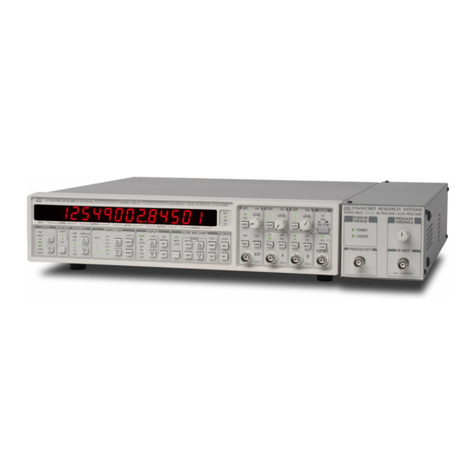
SRS Labs SR625 User manual
SRS Labs
SRS Labs Nitrogen Laser NL100 Operation manual
