SRS Labs SXMCMTU64 User manual

Satellite Radio Superstore | www.SatelliteRadioSuperstore.com | (800) 513-8554 | contactus@SatelliteRadioSuperstore.com | Page 1
Satellite Radio Commander Touch™
SXMCMTU64 UTV Kit Installaon Instrucons
Thank you for purchasing the SiriusXM™ Commander Touch UTV Kit! The SiriusXM™ Commander Touch™ has these
excing features to enhance your overall experience:
• Enjoy SiriusXM through your vehicle’s in-dash audio system with controls on the color touchscreen display
• Compact touchscreen controller mounts directly to the UTV mount for a fully integrated full-color display with
album art, arst name, song tle, channel logos and program informaon
• Pause, Rewind and Replay live Satellite Radio
• Automacally start songs from the beginning on your favorite channels with TuneStart™
• Use TuneMix™ to hear a mix of songs from your favorite channels
• Keep moving with the most current updates using Trac & Weather Now™
• Connects to any radio with either an AUX input or FM connecon
• Professional installaon recommended for best results
• Can be updated by a USB ash drive (not included) to add new features and capabilies as they become available
• Works on the XM Network
Package Includes:
(1)Commander Touch™ Controller
(1) SiriusXM™ Radio Tuner with Mul Pin Cable
(1) SiriusXM™ Antenna
(1) FMDA25 Direct Wire Adapter
(1) Rubber Wrap for Controller
(1) Female AMPS Plate / (1) Male AMPS Plate
(1) RAM Mount Adapter
(1) Adhesive Swivel Mount
(1) AUX Audio Cable
Addional Resources
Scan the QR codes below for addional installaon documentaon, support arcles and user manuals.
1
2
Online Installaon Guide Commander Touch™
User Guide
Commander Touch™
Update Instrucons
Need help?
Scan the QR code for
SMS/Text support

Satellite Radio Superstore | www.SatelliteRadioSuperstore.com | (800) 513-8554 | contactus@SatelliteRadioSuperstore.com | Page 2
Install the Rubber Case Around Controller
Follow the steps below to install the case around the controller.
1
2
Insert the cable into the hole in the
boom le of the case from inside out.
Pull the cable all the way through the hole and
push the controller ush to the end of the case.
Pull the rubber case around the controller.
Prepping the Rubber Case
The rubber case is used to keep out dust and water from the edges of the
Commander Touch™ controller. On the back of the case are four holes used
to mark the locaon of the four screw holes on the back of the controller.
It is recommended to use a small screw driver to push through the case
inside the circles and make a small hole. This will allow the screws to pass
through the case when mounng the case. This step can also be done aer
the case has been installed on the Commander Touch™ controller.
Aaching the Dual Mounng Plate
Locate the Dual Male AMPS Plate from the bag of parts along with the screws. Use a screw driver or other tool to
push a hole through the back of the case in the designated circles marked on the back of the case. Next, take the
Dual Male AMPS Plate and screw it to the back of the rubber case making sure the screw goes all the way through
the case to the screw hole. Be sure to not overghten the screws.
Dual Male AMPS Plate

Satellite Radio Superstore | www.SatelliteRadioSuperstore.com | (800) 513-8554 | contactus@SatelliteRadioSuperstore.com | Page 3
Mount Assembly Opons
Before geng started, it is recommended to locate an installaon spot on your UTV that will allow you to see the
screen of the receiver and operate the unit safely while driving. There are three dierent mounng opons included
with this kit. Select the opon that best ts your UTV and installaon requirements.
FLUSH MOUNT
Locate the Dual Female AMPS Plate in the parts bag.
RAM Mount Adapter
Dual Female AMPS Plate
Using four screws or adhesive tape screws mount the Dual Female AMPS
Plate on the dash or other desired locaon.
RAM MOUNT
Locate the RAM Mount Adapter Plate in the parts bag.
Next line up the dual T notches on the back of the controller with the slots
on the Dual Female AMPS Plate and push the controller down. The picture
on the le shows what the plate will look like from the back when the
notches line up with the slots. Be sure to mount the DUAL Female AMPS
Plate to the surface before sliding the display onto the plate.
Using the provided screws aach the
RAM Mount Adapter to the back of the
display. Be sure to press the screws all
the way through the rubber case so
they insert into the screw holes.
ADHESIVE SWIVEL MOUNT
Locate the Adhesive Swivel Mount and the Dual Female AMPS Plate in the bag of parts. Aach the Dual
Female AMPS Plate to the Adhesive Swivel Mount with the provided screws and nuts. Next, slide the display
controller onto the Dual Female AMPS Plate.
Adhesive Swivel Mount
Dual Female AMPS Plate

1) Selecng the Correct Antenna Adapter
Included in the kit are two FAKRA antenna adapters that are used to connect the FMDA25 to the Ride Command®
antenna system. For vehicles prior to 2020 use the blue colored adapter. For vehicles manufactured in 2020 and
newer use the cable with the black FAKRA connector.
Blue for vehicles prior to 2020
Black for 2020 vehicles and newer
Universal antenna adapter cable
2) Connecng Adapters to FMDA25
If your vehicle has an AM/FM antenna to you can sll use the antenna with the FMDA25. The FMDA25 allows the
AM/FM signal to pass-thru to the Ride Command® system (or other aermarket stereo system).
1. Connect the RCA-FKA adapter cable into the female socket on the TO VEHICLE FM ANTENNA port on the
FMDA25
2. Connect the PRC-FKA (or V2 RIDECO per step 1) to the TO VEHICLEL FM RADIO port on the FMDA25
RCA-FKA
Installaon without AM/FM Antenna
If there is no AM/FM antenna installed in the vehicle the RCA-FKA antenna adapter
is not needed and the port labeled TO VEHICLE FM ANTENNA should be le open.
PRC-FKA or V2 RIDEOCO
Satellite Radio Superstore | www.SatelliteRadioSuperstore.com | (800) 513-8554 | contactus@SatelliteRadioSuperstore.com | Page 4

3) Locate the RIDE COMMAND® AM/FM Antenna Port
Locate the AM / FM antenna connector in your UTV. The color and locaon may vary based on the year and model
of your vehicle. In our example it is the connect on the right of the connecon cluster shown below.
1
2
3
4) Connect the FMDA25 to the Vehicle AM/FM Antenna Port
Plug the connecon from the FMDA25 labeled
"TO VEHICLE FM RADIO" into the RideCommand®
Antenna port. Make sure the connector is pushed all
the way down and the FAKRA connectors snaps in.
If the vehicle has an AM/FM antenna connect the
aqua colored connector on the port labeled
“TO VEHICLEL FM RADIO”. Make sure the connector is
pushed all the way down and the FAKRA connectors snaps in.
Satellite Radio Superstore | www.SatelliteRadioSuperstore.com | (800) 513-8554 | con[email protected] | Page 5

Step 5) Connect the Audio Cables to the SiriusXM Dock
Satellite Radio Superstore | www.SatelliteRadioSuperstore.com | (800) 513-8554 | con[email protected] | Page 6
Step 6) Connecng Power and Power Opons
Included in the package are 3 power opons
1. Hardwired Power Adapter
2. USB Power Cable
3. SXDPIP1 Cigaree Lighter Power Adapter
Connecng Power
Once you have selected your power opon connect the power
adapter to the power port on the docking cradle (PWR). If using
the hardwired power adapter please reference the installaon
instrucons provided in the packaging.
Please Note - Each power opon will work with the docking cradle that is included in
the kit. Feel free to select the power opon that best meets your installaon needs.
On the FMDA25 locate the audio cable labeled "TO SIRIUS RADIO" and connect the cable into the FM Port on the
docking cradle. Shown by the arrows in the pictures below.

7) SiriusXM Radio Antenna Installaon
Once you have the audio and power connected it's me to install the SiriusXM Radio antenna.
It is recommended to select a locaon on your UTV that will allow the antenna to have maximum clearance from a
roof or other objects.
8) Connecon the Antenna to the Cradle
1. Run the antenna cable from the antenna either inside the roll cage pipe
tubing or along the outside securing the antenna cable with cable es
(not supplied). Be sure not to over ghten the cable es as the stress
could cause damage to the antenna wire.
2. Bring the antenna connecon to the desired locaon (dry box is
recommended) to the SiriusXM receiver. It is recommended to leave a
couple of inches of play in the cable.
3. Connect the antenna wire to the antenna port (ANT) on the docking
cradle.
4. If you need addional cable length to run the antenna you can
purchase SiriusXM antenna extension cables from our website.
9) Power Up and Tune Radio
Aer connecng the antenna, power, and audio to
the receiver docking cradle you will need to tune
the Radio to an empty FM radio channel.
To nd an empty FM channel in your area visit:
hps://www.siriusxm.com/frequency
If there is stac we recommend to select a dierent FM channel.
Satellite Radio Superstore | www.SatelliteRadioSuperstore.com | (800) 513-8554 | con[email protected] | Page 7
Antenna Installaon Tips
• Magnec Antenna - It is recommended to place the antenna on a
metal surface as high as possible on the vehicle such as the roof or
roll bar. This antenna requires a ground plane for opmal recepon.
• For installing the UTV Post Antenna refer to those instrucons.

Commander Touch Connecons
Display Controller Connecons
Display Controller Pigtail Cable: Connects to the DISP connecon on the Tuner Module.
Micro USB Port: SiriusXM may occasionally release a system soware update for Commander Touch.
The update can be installed by connecng a USB Flash Drive with the soware update to the micro
USB port located at the boom of the Display Controller. A micro USB Flash Drive or a USB type A
Flash Drive with a USB type A to Micro USB Adapter is required (not included)
Tuner Module Connecons
Satellite Radio Superstore | www.SatelliteRadioSuperstore.com | (800) 513-8554 | contactus@SatelliteRadioSuperstore.com | Page 8
ANT (Antenna): Connecon for the Magnec Mount Antenna.
FM: Connecon for the FMDA25 FM Direct Adapter.
AUX (Auxiliary audio output): Connecon for the AUX Audio Cable.
PWR (Power): Connecon for the Wiring Harness.
DISP (Display): Connecon for the Display Controller pigtail cable.
Installaon Wiring Diagram
Refer to the wiring diagram below and install the Power Wiring Harness, and the AUX In or FM Input audio connecon.

Install the Power Wiring Harness
The wiring harness has 4 wires: BAT (baery, yellow); ACC (accessory, red); ILL (illuminaon, orange); GND (ground,
black). When installing the harness, keep the fuse holder which is connected to the BAT wire in a locaon that is
accessible in case the fuse ever needs to be replaced.
1. Plug the Wiring Harness connector to the PWR connector on the Tuner Module.
2. Route and connect the BAT yellow wire to a constant 12 volt source, a source which is
always on even when the motorcycle is turned o.
3. Route and connect the ACC red wire to a switched 12 volt source, a source which
provides power only when the vehicle is turned on . This should be ed to the motorcycle’s accessory wire.
4. Route and connect the ILL orange wire to a 12 volt source which is on ONLY when the motorcycle’s exterior
parking or headlights are turned on. DO NOT connect to the Dimmer line as the voltage uctuates. Connecon to
the ILL wire is oponal, but it will allow you to take advantage of the independent Auto Day/Night brightness
seng opon.
5. Route and connect the GND black wire to the motorcycle ground connecon, usually the motorcycle’s chassis.
Install Audio Connecon
There are two ways to connect the audio for the Commander Touch: using the AUX Audio Cable, or using the
FMDA25 FM Direct Adapter. Both audio connecon soluons are included with the Commander Touch and both
audio soluons can be acve at the same me.
• AUX Audio Cable: Best: If your motorcycle’s radio has a auxiliary input jack, this is the easiest way to connect
the audio and provides excellent audio .
• FMDA25 FM Direct Adapter: Good: The FMDA25 FM Direct Adapter directly connects the FM signal from the
Commander Touch to the motorcycle’s radio, reducing any interference which might be present from FM radio
staons. When the Commander Touch is turned o, the motorcycle’s FM antenna is automacally connected
back to the motorcycle’s radio. The FMDA25 FM Direct Adapter connects directly in-line with the motorcycle’s
exisng AM/FM antenna input. Follow the instrucons below for the audio connecon you have selected.
Connecng the Audio Using the AUX Audio Cable
The auxiliary input jack may be located on the face plate of the motorcycle’s radio, on the back of the radio, or
anywhere on the front dash panel.
1. Connect the AUX Audio Cable to the auxiliary input jack of the motorcycle radio.
2. Connect the other end of the AUX Audio Cable to the AUX.
Connector on the Tuner Module.
3. Turn the motorcycle’s radio on, and set it to the AUX In source.
4. Press the Power buon on the Commander Touch Display Controller. Aer the
start up sequence you should hear SiriusXM Preview Channel 1 through your motorcycle’s radio.
Satellite Radio Superstore | www.SatelliteRadioSuperstore.com | (800) 513-8554 | contactus@SatelliteRadioSuperstore.com | Page 9

5. The audio level can be adjusted by swiping to the Sengs page, tap Audio Opons, then tap Audio Output Level
and adjust the audio output level.
Connecng the Audio Using the FMDA25 FM Direct Adapter
Certain models of motorcycles will require adapters to connect the AM/FM antenna to the FMDA25 and to connect
the FMDA25 to the motorcycle’s radio. These adapters are sold separately at auto parts stores or by professional
installers.
1. Remove the motorcycle’s radio from the dash and disconnect the AM/FM antenna cable from the rear of
the motorcycle’s radio.
2. Plug the FM Antenna Connector (A) from the FMDA25 into the same connector on the vehicle’s radio.
(Addional antenna adapter may be required.)
3. Plug the motorcycle’s AM/FM antenna cable into the female FM Antenna Socket (B) of the FMDA25.
(Addional antenna adapter may be required.)
4. Plug the Mini Connector (C) of the FMDA25 into the FM connecon of the Tuner Module.
5. If needed reinstall the radio.
6. The FMDA25 should be secured in a hidden locaon on the bike.
7. Turn the vehicle’s radio on and tune it to FM channel 97.9.
8. Press the Power buon on the Commander Touch Display Controller. Aer the start up sequence, you
should hear SiriusXM Preview Channel 1 through your vehicle’s radio.
Satellite Radio Superstore | www.SatelliteRadioSuperstore.com | (800) 513-8554 | contactus@SatelliteRadioSuperstore.com | Page 10

9. The audio level can be adjusted by swiping to the Sengs page, tap Audio Opons, then tap Audio Output Level
and adjust the audio output level.
NOTE! The Audio Output Level adjusts both the AUX audio output level as well as the FMDA audio output
level. Use cauon when making the adjustments. For FM, it is recommended to adjust the level to MAX.
10. If channel 97.9 has stac or interference, other FM channels can be selected by swiping to the Sengs page,
tap FM and adjust the FM channel. Tap a + buon to save it as a preset. Set the vehicle’s radio to the same FM
channel.
The installaon is now complete you are ready to acvate the CommanderTouch.
Subscribe to SiriusXM Radio Programming
Follow these steps to subscribe your Commander Touch. Once you have successfully acvated the Commander
Touch, you will be able to tune to other channels.
1. Make sure your Commander Touch is turned on, receiving the SiriusXM signal, and tuned to Preview Channel 1
so that you can hear the SiriusXM audio.
2. Make a note of your Radio ID. You can nd it by swiping to Sengs and tapping About, by tuning to channel 0,
on a label on the boom of the gi box, and on the label on the back of the Commander Touch Tuner Module .
3. NOTE! The Radio ID does not use the leers I, O, S, or F .
4. To subscribe:
• Online: www.siriusxm.com/acvatenow to access or set up an online account, subscribe to the service,
and acvate your Commander Touch
• Phone: Call 1-866-587-4225 (If calling to acvate, be sure to menon “Never Miss A Beat”). Acvaon
usually takes 10 to 15 minutes aer you have completed the subscripon process, but may take up to an
hour. We recommend that your Commander Touch remain on unl subscribed. Once subscribed, the
Commander Touch will receive, and you can tune to, the channels in your subscripon plan.
Satellite Radio Superstore | www.SatelliteRadioSuperstore.com | (800) 513-8554 | contactus@SatelliteRadioSuperstore.com | Page 11
Table of contents
Other SRS Labs Measuring Instrument manuals
SRS Labs
SRS Labs SIM970 Operation manual

SRS Labs
SRS Labs SR715 User manual

SRS Labs
SRS Labs UGA100 User manual
SRS Labs
SRS Labs SIM922A Operation manual

SRS Labs
SRS Labs SR785 User manual
SRS Labs
SRS Labs SR1 Manual
SRS Labs
SRS Labs SR625 User manual
SRS Labs
SRS Labs BGA244 User manual
SRS Labs
SRS Labs SIM940 Operation manual
SRS Labs
SRS Labs SR780 User manual
Popular Measuring Instrument manuals by other brands
sauter
sauter SAUTER TE SERIES instruction manual

SBS
SBS SBS-3510 Instruction Manual and Safety Information

EUCOL
EUCOL U2683 Operation manual
FASTLITE
FASTLITE MOZZA operating manual
Agilent Technologies
Agilent Technologies E2730A Installation and operation manual
Konica Minolta
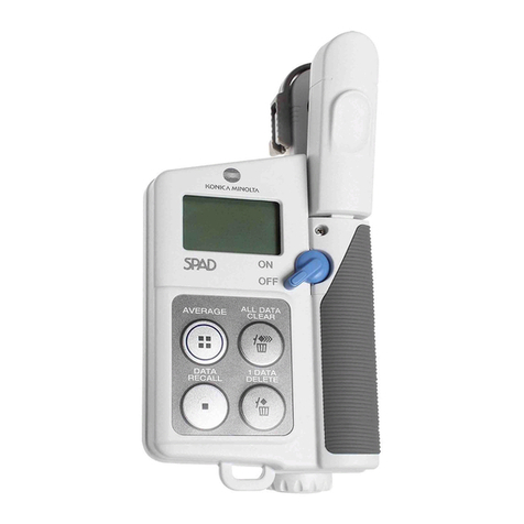
Konica Minolta SPAD-502 PLUS brochure
