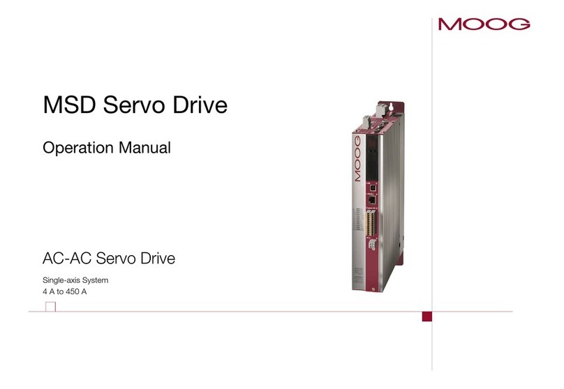
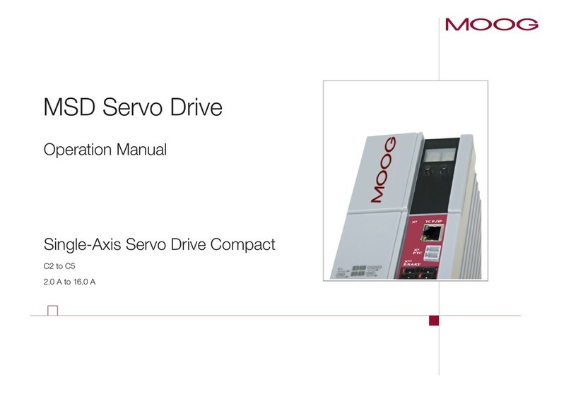
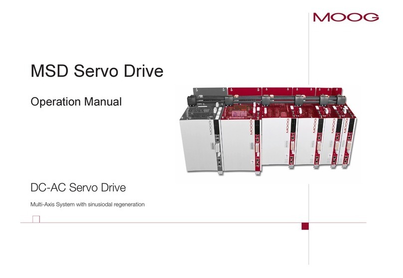
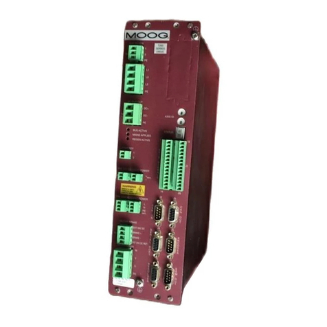
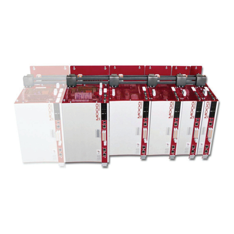
Moog MSD User manual

moog
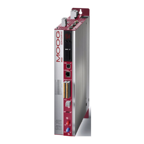
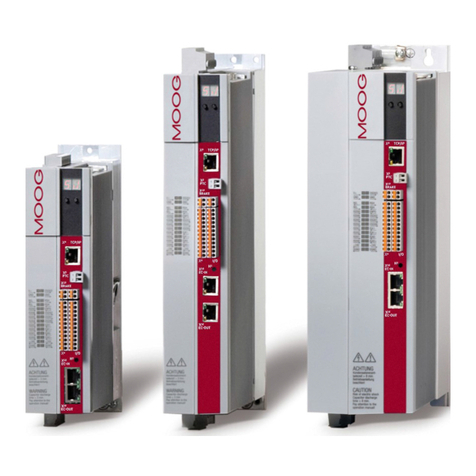
MSD Servo Drive
User Manual
Single-Axis System
Multi-Axis System
Compact

moog MSD Servo Drive User Manual Profibus
Profibus for MSD Servo Drive user manual
Id. no.: CA65645-001, Rev. 2.0
Da te : 0 8 / 20 11
We reserve the right to make technical changes.
Technical alterations reserved.
The contents of our documentation have been compiled with greatest care and in com-
pliance with our present status of information.
Nevertheless we would like to point out that this document cannot always be updated
parallel to the technical further development of our products.
Information and specifications may be changed at any time. For information on the
latest version please refer to drives-support@moog.com.
This document details the functionality of the following equipment variants:
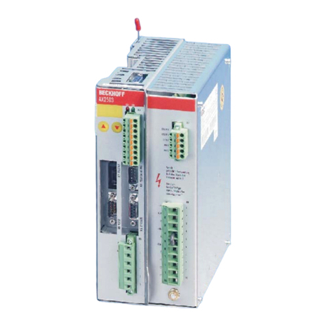
MSD Servo Drive Single-axis system
MSD Servo Drive Multi-axis system
MSD Servo Drive Compact

moog MSD Servo Drive User Manual Profibus 3
Table of contents
How to use this manual.................................................................. 5
1 General ................................................................................... 7
1.1 Measures for your Safety ........................................................................................7
1.2 Introduction to Profibus ..........................................................................................7
1.3 System requirements...............................................................................................7
1.4 Further documentation ...........................................................................................8
2 Commissioning the Profibus Interface....................................... 9
2.1 Connections and user controls................................................................................9
2.2 Plug configuration for the P
rofibus
cable..................................................................9
2.3 Bus termination.......................................................................................................10
2.4 Setting the drive address.........................................................................................10
2.5 Operating displays ..................................................................................................11
2.6 GSD file...................................................................................................................11
3 Cyclic data transmission – DPV0 ............................................. 13
3.1 Parameter process data objects (PPO) .....................................................................13
3.1.1 Standard “PROFIdrive” telegrams ................................................................13
3.1.2 User-specific PPOs .......................................................................................15
3.1.3 PKW parameter channel ..............................................................................19
3.2 Master control word ...............................................................................................20
3.2.1 Jog mode speed mode ................................................................................21
3.2.2 Jog mode positioning mode ........................................................................22
3.2.3 Jog mode reference value parameter ...........................................................22
3.3 Drive status word....................................................................................................22
3.4 Drive status machine...............................................................................................24
4 Acyclic data transmission – DPV1 ........................................... 27
4.1 Examples of request and reply telegrams ................................................................32
5 Operating modes................................................................... 35
5.1 Speed Control.........................................................................................................35
5.2 Speed control circuit and associated control parameters .........................................36
5.3 Position control.......................................................................................................37
5.4 Position control circuit and associated control parameters ......................................39
6 Homing ................................................................................. 41
6.1 Homing runs performed by the drive ......................................................................41
6.2 Homing run speed ..................................................................................................41
6.3 Homing run acceleration.........................................................................................41
6.4 Zeroing offset .........................................................................................................41
6.5 Homing cams, limit switches...................................................................................41
6.6 Homing run methods..............................................................................................43
7 Examples of commissioning using manufacturer-specific
telegrams .............................................................................. 45
7.1 Position control using PPO 5 ...................................................................................45
7.2 Conversion of reference values and actual values using factor group parameters....46
7.3 Examples for setting the user factor group..............................................................48
7.4 Speed control using PPO 2 ......................................................................................48
7.4.1 Speed input .................................................................................................49
7.5 Mappable parameters.............................................................................................50
8 Profibus parameters............................................................... 51
9 Appendix Glossary................................................................. 53

moog MSD Servo Drive User Manual Profibus 4

moog MSD Servo Drive User Manual Profibus 5
How to use this manual
Dear user!
This manual is intended for use by project engineers, commissioning engineers and pro-
grammers of drives and automation solutions involving the Profibus fieldbus.
It assumes that you have received appropriate training on Profibus and that you have
access to relevant reference books. We assume that your drive has already been commis-
sioned – if not, please first refer to the user manual.
11 General
44 Acyclic data transmission - DPV1
55 Operating modes
66 Homing
Appendix: Glossary, key words directory
33 Cyclic data transmission - DPV0
22 Commissioning the Profibus interface
77 Commissioning examples
88 Profibus parameters

moog MSD Servo Drive User Manual Profibus 6
Pictograms
Attention! Incorrect operation may damage the drive or cause it to malfunc-
tion.
Danger from electrical tension! Improper conduct may endanger human life.
Danger from rotating parts! The drive may start up automatically.
Note: Useful information

moog MSD Servo Drive User Manual Profibus 7
[ Kapitel 1 ]
1 General
1.1 Measures for your Safety
Servo controllers of the MSD Servo Drive family are quick and easy to handle. For your
own safety and for the safe functioning of your device, please be sure to observe the
following points:
Read the Operating Manual first!
1.
• Follow the safety instructions!
Electric drives are subject to certain hazards:
• Electric voltages > 230 V/460 V:
Dangerously high voltages may still be present 10 minutes after the power
is switched off. so always make sure the system is no longer live!
• Rotating parts
• Hot surfaces
Your qualification:
• In order to prevent personal injury or damage to property, only personnel
with electrical engineering qualifications may work on the device.
• Knowledge of the national accident prevention regulations (such as VBG4
in Germany)
• Knowledge of structure and networking using the CAN fieldbus
U
V
N
L+
RB
L-
L3
L2
L1
U
V
N
L+
RB
L-
L3
L2
L1
During installation observe the following instructions:
• Always comply with the connection conditions and technical specifications.
• Standards for electrical installation, e.g. cable cross-sections, screening etc.
• Do not touch electronic components and contacts (electrostatic discharge
may destroy components)
1.2 Introduction to Profibus
The Profibus implementation in MSD Servo Drive is based on the PROFIdrive profile
“Profibus PROFdrive profile version 4.0” dated August 2005.
Performance features in key words
–Data transmission using two-wire twisted pair cable (RS 485)
–Transmission rate: optionally 9.6 K, 19.2 K, 45.45 K, 93.75 K, 187.5 K, 500 K,
1.5 M, 3 M, 6 M or 12 MBaud
–Automatic Baud rate detection
–Profibus address can be set using the rotary coding switches or alternatively
using the addressing parameters
–Cyclic data exchange reference and actual values using DPV0
–Acyclic data exchange using DPV1
–Synchronisation of all connected drives using freeze mode and sync mode
–Reading and writing drive parameters using the PKW channel or DPV1
1.3 System requirements
It is assumed that you have access to a standard Profibus set-up program or a Profibus
interface driver.

moog MSD Servo Drive User Manual Profibus 8
1.4 Further documentation
•User manual for commissioning the drive device
•User manual for further parameterisation to customise the application.
•The User Manual can be downloaded as a PDF file from the Product DVD, which is
enclosed the MSD Servo Drive.
•CiA 301 (Rev. 4.0): Application Layer and Communication Profile
•CiA 402 (Rev. 2.0): Device Profile Drives and Motion Control
•Profibus User Organisation „Profidrive - Profil Drive Technology for Profibus and
Profinet“ Version 4.1, May 2006, Order no. 3.172

moog MSD Servo Drive User Manual Profibus 9
[ Chapter 2 ]
2 Commissioning the
Profibus Interface
2.1 Connections and user controls
The connections and user controls for the Profibus interface are shown schematically
in Figure 2-1. The LEDs H1, H2, H3 act as status indicators. The rotary coding switches
S1 and S2 can be used to set the Profibus address for the drive. The Profibus cable is
connected to the plug X14.
Front plate No. Comments
H1 LED for status indication (yellow)
H2 LED for status indication (red)
H3 LED for status indication (green)
S1 Rotary coding switch for setting the Profibus address for the
drive = 0x(S2)(S1)
S2 Rotary coding switch for setting the Profibus address for the
drive = 0x(S2)(S1)
X14 Profibus cable connection
Table 2.1 Profibus options card
2.2 Plug configuration for the Profibus cable
The Profibus is connected using a nine-pin sub-D plug. The pin assignment is shown in
Fig. 2-2 and described in Table 2.1.
Figure 2.1
X14
12345
6789
RxD
TxD-P DGND
RxD
TxD-N
VP
5 Volt
Pin assignment of sub-D-plug connector
PIN RS-485 Signal Description
1SHIELD Earthed shield
2RP Reserved for power supply via the bus
3B/B’ (red) RxD / TxD-P Send and receive data (+)
4CNTR-P Control signal for repeater (+)
5C/C’ DGND Data reference potential and power supply to
terminating resistor (-)
6VP Power supply for terminating resistor (+)
7RP Reserved for power supply via the bus
8A /A’ ( gr ee n) RxD / TxD-N Send and receive data (-)
9CNTR-N Control signal for repeater (-)
Table 2.2 Description of pin assignment
The pin assignments shown with dark backgrounds in the table are not necessary from
the user’s point of view. The control signals used for the repeaters are optional, and the
power supply for the terminating resistors is provided by the device.

moog MSD Servo Drive User Manual Profibus 10
2.3 Bus termination
If the servo controller is initially at the end of the bus system, a plug with an integral
terminating resistor Rt should be used. In addition to the cable terminating resistor in ac-
cordance with the EIA-485 standard, a pull-down resistor Rd against the data reference
potential DGND and a pull-up resistor Ru against VP are provided. This ensures a defined
no-load potential of 1.1 Volt between pins 3 and 8. In a made-up Profibus cable these
resistors are all incorporated as standard in the Profibus plug and the terminating resistor
can be activated using a switch on the Profibus plug. The following figure shows a Sub-
D 9-pin plug bus termination.
Figure 2.2
Plug Profibus cable
Device
Vp = 5 Volt (6)
RxD TxD-P (3)
RxD TxD-N (8)
GND (6)
Ru = 390 Ohm
Rt = 220 Ohm
Rd = 390 Ohm
B (red)
A (green)
Sub-D 9-pin plug bus termination
2.4 Setting the drive address
The drive address can be set as standard using the rotary coding switches on the options
card (see Fig. 2-1). The address range runs from 0 to 125. The drive address is not loaded
until a 24 Volt reset has been applied to the device.
The drive address can also be assigned using parameter P 0918 COM_DP_Address.
For this purpose the rotary coding switches must be set to value in excess of 125.
The drive address set by software address is not loaded until a 24 Volt reset has been
applied to the device.
In the MSD Servo Drive Compact the address cannot be set using the switches.
On all devices the bus address can also be set using the buttons on the device, see ope-
rating instructions for MSD Servo Drive Compact.
Diagnostics can be performed on the MSD Servo Drive Compact using the internal
control unit in the device. The control unit comprises the following elements that are all
positioned on the front:
•2-digit 7-segment display (1, 2)
•2 buttons (3, 4)
Figure 2.3
1
2
3
4
Integrated control unit MSD Servo Drive Compact

moog MSD Servo Drive User Manual Profibus 11
[ Chapter 2 ]
The following functions and indications are available:
•Indication of the device status
The device status is indicated after switching on the control supply. If an entry is
not made using the buttons for 60 seconds, the display returns to the display of
the device status.
•Indication of the device error status
On the occurrence of an error in the device, the display is immediately switched to
the indication of the error code.
•Parameter setting (indication „PA“)
Reset the device parameter settings to the factory setting
•Ethernet IP address setting (indication „IP“)
Setting for the Ethernet IP address as well as the subnet mask
•Fieldbus settings (indication „Fb“)
Setting e.g. for the fieldbus address
2.5 Operating displays
Options module: Three LEDs are mounted on the options card; these give indications
regarding the current operating status of the module. In Tables 2-2 and 2-3 the opera-
ting statuses of the Profibus module are listed, based on the various LED illumination
combinations.
LED 1, green LED 2, red Status
Reset (after switching on)
ASIC RAM test and initialisation
End of ASIC RAM test and initialisation
Table 2.3 Selftest during diagnostic
LED 1, green LED 2, red Status
Seeking Baud rate after switching on without bus
connection
Seeking Baud rate after the bus connection has
already been established
Awaiting parameterisation data
Table 2.4 Operation diagnostics
LED 1, green LED 2, red Status
Communication: Data exchange without acyclic
master class 2 connection. Yellow LED lights up.
Communication: Data exchange “clear state”
Incorrect parameterisation data
Incorrect configuration data
Communication: Data exchange with acyclic
master class 2 connection.
Table 2.4 Operation diagnostics
LED 3, yellow Status
Device is exchanging data
Table 2.5 Data exchange
2.6 GSD file
The device master data file contains the summary of the device features in a standar-
dised form. The device features include for instance the device name, the bus timing,
the extended services available and the modules that can be selected (telegram types).
In order to use different telegram types, the GSD file must be linked in at the configura-
tion phase of the Profibus network. This file contains, as well as the standard “Profidrive
Profile” telegrams, additional manufacturer-specific telegram types.

moog MSD Servo Drive User Manual Profibus 12

moog MSD Servo Drive User Manual Profibus 13
[ Chapter 3 ]
3 Cyclic data transmission –
DPV0
3.1 Parameter process data objects (PPO)
The establishment of communications between a class 1 master and the
MSD Servo Drive servo controller is essentially performed in three phases. Firstly the
MSD Servo Drive is parameterised with the current bus parameters, monitoring times
and drive-specific parameters (phase 1). In the configuration phase a configuration sent
by the master is compared with the actual MSD Servo Drive configuration (phase 2).
Once these two phases have been completed successfully, the cyclic user data traffic
starts (phase 3).
The various telegram types (Parameter Process Data Objects - PPO) are prepared in the
GSD file. These PPOs form the basis of the configuration phase. The project engineer
knows from the GSD file how many bytes are required for the input and output data for
Profibus communication between the master and the servo controller and can use this
information to perform his settings in the configuration tool. As well as the standard
telegrams in accordance with the “PROFIdrive – Profile”, there are additional user-
specific telegram types. In addition to the PZD process data channel, the user-specific
telegram make partial use of a PKW parameter channel.
3.1.1 Standard “PROFIdrive” telegrams
The table below lists firstly the standard “Profidrive” telegrams that are supported by the
servo controller. Table 3-1 explains the abbreviations used to assign standard telegrams
to a specific process data channel. The process data channel (abbreviated to PZD) is
grouped by words.
Abbreviation Name Number of words
STW1 Control word 1 1
STW2 Control word 2 1
ZSW1 Status word 1 1
ZSW2 Status word 2 1
NSOLL_A Speed reference 1
NIST_A Actual speed 1
SATZ ANW Set selection (from the driving set table) 1
AKTSAT Z Current set selection (from the driving set
table)
1
XSOLL_A Reference position 2
XIST_A Actual position 2
TARPOS_A Reference destination position 2
VELOCIT Y_ A Reference speed 2
Figure 3.1 Abbreviations
Standard telegram 1 is a defined telegram type for speed control. It consists of two input
words and two output words as shown in the following table.
PZD number 1 2
Reference values STW1 NSOLL_A
PZD number 1 2
Actual values ZSW1 NIST_ A
Table 3.1 Standard telegram 1
Standard telegram 7 is a defined telegram type for selecting the driving set. In total 16
driving sets saved in the drive can be selected. The telegram type comprises 2 input
words and two output words as in the following table.
PZD number 1 2
Reference values STW1 SAT ZANW
PZD number 1 2
Actual values ZSW1 AKTSATZ
Table 3.2 Standard telegram 7

moog MSD Servo Drive User Manual Profibus 14
Standard telegram 8 is a defined telegram type for positioning with the facility for spe-
cifying a positioning speed. It consists of 5 input words and 5 output words as shown in
the following table.
PZD number 12345
Reference values XSOLL_A STW2 NSOLL_A
PZD number 12345
Actual values XIST_A ZSW2 NIST_A
Table 3.3 Standard telegram 8
Standard telegram 9 is a defined telegram type for positioning. It consists of 6 input
words and five output words as shown in the following table.
PZD number 123456
Reference values STW1 TARPOS_ A STW2 VELOCITY_A
PZD number 12345
Actual values ZSW1 XIST_A ZSW2 NIST_ A
Table 3.4 Standard telegram 9
Every standard telegram in the device is described in the GSD file by a PROFIdrive Profile
configuration identifier (ID). The following table shows these identifiers for the selected
standard telegrams.
Telegram type Data area Identifier (ID)
Standard telegram 1 2 output words and 2 input words 0xC3 0xC1 0xC1 0xFD 0x00 0x01
Standard telegram 7 2 output words and 2 input words 0xC3 0xC1 0xC1 0xFD 0x00 0x07
Standard telegram 8 5 output words and 5 input words 0xC3 0xC4 0xC4 0xFD 0x00 0x08
Standard telegram 9 6 output words and 5 input words 0xC3 0xC5 0xC4 0xFD 0x00 0x09
Table 3.5 Identifier

moog MSD Servo Drive User Manual Profibus 15
[ Chapter 3 ]
3.1.2 User-specific PPOs
As well as the standard telegrams that are supported there are in addition further user-
specific PPOs (Parameter Process data Objects). The following PPOs are also transmitted
cyclically and in addition to the PZD process data channel partially contain a PKW para-
meter channel, thereby allowing access to the drive parameter values.
PPO PKW PZD
1PKE IND PKW
1
PKW
2
STW/
ZSW
REFERENCE VALUE/
ACTUAL VALUE
--------
2PKE IND PKW
1
PKW
2
STW/
ZSW
REFERENCE VALUE/
ACTUAL VALUE
PZD
3
PZD
4
PZD
5
PZD
6
----
3* - - - - STW/
ZSW
REFERENCE VALUE/
ACTUAL VALUE
--------
4 - - - - STW/
ZSW
REFERENCE VALUE/
ACTUAL VALUE
PZD
3
PZD
4
PZD
5
PZD
6
----
5PKE IND PKW
1
PKW
2
STW/
ZSW
REFERENCE VALUE/
ACTUAL VALUE
PZD
3
PZD
4
PZD
5
PZD
6
PZD
7
PZD
8
PZD
9
PZD
10
- - - - STW/
ZSW
REFERENCE VALUE/
ACTUAL VALUE
PZD
3
PZD
4
------
PKE IND PKW
1
PKW
2
STW/
ZSW
REFERENCE VALUE/
ACTUAL VALUE
PZD
3
PZD
4
------
- - - - STW/
ZSW
REFERENCE VALUE/
ACTUAL VALUE
PZD
3
PZD
4
PZD
5
PZD
6
PZD
7
PZD
8
- -
PKE IND PKW
1
PKW
2
STW/
ZSW
REFERENCE VALUE/
ACTUAL VALUE
PZD
3
PZD
4
PZD
5
PZD
6
PZD
7
PZD
8
- -
- - - - STW/
ZSW
REFERENCE VALUE/
ACTUAL VALUE
PZD
3
PZD
4
PZD
5
PZD
6
PZD
7
PZD
8
PZD
9
PZD
10
(*) PPO3 is the standard telegram 1
Table 3.6 User-specific Parameter Process data Objects

moog MSD Servo Drive User Manual Profibus 16
In the drive parameter list there exist two signal tables, which contain all the process
data that can be cyclically read and written for the Profibus communications DPV0. All
possible process data signals that can be written can be found in the signal table
P 1284 COM_DP_SignalList_Write and all possible process data signals that can be read
can be found in the signal table P 1285 COM_DP_SignalList_Read. The most important
parameters that can be read and written are also documented in Chapter 6.
The process data signals that can be written can be configured in the signal table
P 0915 COM_DP_PZDSelectionWrite. The number of process data available to be written
are determined by the PPO type that is selected.
The process data signals that can be read can be configured in the signal table
P 0916 COM_DP_PZDSelectionRead. The number of process data available to be read are
also determined by the PPO type that is selected.
When using standard telegrams the process data signals in the signal tables are automa-
tically configured by the firmware.
A maximum of 15 process data signals can be „mapped“. Here both words and double
words can be used.
The user-specific drive telegram types are described by a configuration identifier (ID) in
the GSD file. This describes the structure of the cyclic report data using a special identifi-
cation format shown in the figure below.
Figure 3.2 Identification format (Identifier)
After the parameterisation phase, the master sends the drive a configuration telegram
containing this special identification (ID). On receipt of this, the drive compares the data
in the configuration telegram with the configuration held in the drive. The identifier
determined by the PPO type can be found in the GSD file under the heading “Modules”.
The following table shows these identifiers for the user-specific telegrams.
Length of the data
00 = 1 byte/word
15 = 16 bytes/words
Input/Output
00 = specic identication format
01 = input
10 = output
11 = input/output
0 = byte, 1 = word
0 = consistency over byte/word
1 = consistency over the overall
length

moog MSD Servo Drive User Manual Profibus 17
[ Chapter 3 ]
PPO
type
Identifier
(ID) Hex
Identifier
(ID) Bin Evaluation using the special identification format (Figure 3.6) Reference to Table AK
slave-master
10xF3
0xF1
1111 0 011
1111 0 0 0 1
4 words input/output data (consistent overall length)2 words input/output
data (consistent overall length) PKW channel
20xF3
0xF5
1111 0 011
1111 0101
4 words input/output data (consistent overall length)6 words input/output
data (consistent overall length) PZD channel
30xF1 1111 0 0 0 1 2 words input/output data (consistent overall length) PKW channel
40xF5 1111 0101 6 words input/output data (consistent overall length) PZD channel
50xF3
0xF9
1111 0 011
1111 1 0 01
4 words input/output data (consistent overall length)10 words input/output
data (consistent overall length) PZD channel
0xF3 1111 0 011 4 words input/output data (consistent overall length) PZD channel
0xF3
0xF3
1111 0 0 11
1111 0 0 11
4 words input/output data (consistent overall length)4 words input/output
data (consistent overall length) PKW channel
0xF7 1111 0111 8 words input/output data (consistent overall length) PZD channel
0xF3
0xF7
1111 0111
1111 0111
4 words input/output data (consistent overall length)8 words input/output
data (consistent overall length) PZD channel
0xF9 1111 1 0 01 10 words input/output data (consistent overall length) PKW channel
0xC0
0xCD
0xCD
14 words input/output data (consistent overall length) PZD channel
0xF3
0xC0
0xCD
0xCD
14 words input/output data (consistent overall length) PZD channel
0xC0
0xD1
0xD1
18 words input/output data (consistent overall length) PKW channel
0xF3
0xC0
0xD1
0xD1
18 words input/output data (consistent overall length) PZD channel
0xC0
0xD5
0xD5
22 words input/output data (consistent overall length) PZD channel
0xF3
0xC0
0xD5
0xD5
22 words input/output data (consistent overall length) PKW channel
Table 3.7 Listing of identifiers

moog MSD Servo Drive User Manual Profibus 18
PPO
type
Identifier
(ID) Hex
Identifier
(ID) Bin Evaluation using the special identification format (Figure 3.6) Reference to Table AK
slave-master
0xC0
0xD9
0xD9
26 words input/output data (consistent overall length)
0xF3
0xC0
0xD9
0xD9
26 words input/output data (consistent overall length) PKW channel
0xC0
0xDD
0xDD
30 words input/output data (consistent overall length)
0xF3
0xC0
0xDD
0xDD
30 words input/output data (consistent overall length) PKW channel
Table 3.7 Listing of identifiers

moog MSD Servo Drive User Manual Profibus 19
[ Chapter 3 ]
3.1.3 PKW parameter channel
Some PPOs offer an additional cyclic parameter channel. This channel allows drive
parameters to the read and written.
PKW
1st byte 2nd byte 3rd byte 4th byte 5th byte 6th byte 7th byte 8th byte
PKE (1 word) IND (1 word) PKW1 (1 word) PKW2 (1 word)
The parameter consists of a total of 4 words: the parameter identifier PKE (1 word), the
sub-index IND (1 word) and the parameter identification word, which occupies the data
area PKW1 (1 word) to PKW2 (1 word). The parameter identification is shown by bits in
the following table.
AK PNU
15 14 13 12 11 10 9876543210
AK Request or reply identification (value range 0..15)
PNU Parameter number (value range 1…4095)
Table 3.8 PKE parameter identification
The following tables list the request identification (master) and the reply identification
(slave).
Request identification Function
0No request
1Request parameter value
2Change parameter value (word)
3Change parameter value (double word)
4Read parameter description
5 -
6Request parameter value (array)
7Change parameter value (array) (word)
8Change parameter value (array) (double word)
Table 3.9 Request identification AK (master slave)
Reply identification Function
0No reply
1 Parameter value sent (word)
2 Parameter value sent (double word)
3Parameter description sent
4 Parameter value (array) sent (word)
5 Parameter value (array) sent (double word)
6 –
7 Request not executable, see error no.
Table 3.10 Reply identification AK (Slave Master)
On reply identification 7 the error number sent to the drive from the master is shown in
the area PKW1 to PKW2. The following table lists these error numbers.
Error Statement
0Impermissible PNU
1Parameter cannot be changed
2 Lower or upper parameter value limit transgressed
3 Defective sub-index
4 Not an array
5Incorrect data type
...
17 Request cannot be executed because of the operating status
18 Other error
Table 3.11 Reply identification AK (Slave Master)
In addition request identification 4 can be used to read a parameter description. The
parameter description receives relevant information regarding the respective parameter.
The following table shows the sub-indexes that can be used to access the individual
parameter structure elements. The sub-index is indicated only by byte 3.
Sub-index Meaning Data type
1Identifier (ID) V2
2Number of field elements or string length Unsigned 16
Table 3.12 Parameter description

moog MSD Servo Drive User Manual Profibus 20
Sub-index Meaning Data type
3Standardisation factor Floating Point
4Variable attributes OctetString 2
5Reserved OctetString 4
6 Name (only the first four bytes are sent) VisibleString 16
7Lower limit value OctetString 4
8 Upper limit value OctetString 4
9Reserved OctetString 2
10 ID extension extension V2
11 PZD reference parameter Unsigned 16
12 PZD standardisation V2
Table 3.12 Parameter description
The identifier (sub-index 1) in the parameter description identifies additional characteris-
tics of the respective parameter. Table 3-8 describes the meaning of the identifier.
Bit Meaning Explanation
15 Reserved
14 Array
13 Parameter value can only be reset If this bit is set, the respective parameter
value can be varied externally only so as to
be set to zero
12 Parameter value was changed to a value
different from the factory settings
If this bit is set, the parameter value is
different from the factory settings
11 Reserved
10 Additional text array can be called up
9 Parameter cannot be written
8Standardisation factor and variable attri-
butes not relevant
This bit is set if the parameter is of a data
type that cannot be used to calculate any
physical values (e.g. data type string)
0 - 7 Data type of the parameter value (value =
“Profi-Drive table 9”)
Table 3.13 Structure of the identifier
3.2 Master control word
Bit Operating mode: Speed Control Operating mode: Positioning control
Bit 15
(MSB)
0Apply relative positioning immedia-
tely after start enable
1Speed mode
Bit 14
0Normal positioning
1Speed mode
Bit 13
0 Not used New reference values activated by toggling the
master control word bit 6
1 Not used New reference values are loaded directly
Bit 12
0 Not used Positioning reference value = absolute
1 Not used Positioning reference value = relative
Bi t 11
0 Not used Stop homing run
1 Not used Start homing run
Bit 10
0 No access rights over the PLC
1 Access rights over the PLC
Bit 9
0 Jog mode 2 off Jog mode 2 off
1 Jog mode 2 on Jog mode 2 on
Bit 8
0 Jog mode 1 off Jog mode 1 off
1 Jog mode 1 on Jog mode 1 on
Bit 7
0Error acknowledgement at rising flank 0 1
1
Table 3.14 Master control word
Other manuals for MSD
3
Table of contents
Other Moog Servo Drive manuals
Popular Servo Drive manuals by other brands
SYNAPTICON
SYNAPTICON SOMANET Circulo 7 manual
Inovance
Inovance SV670P Series troubleshooting guide
Rockwell Automation
Rockwell Automation Allen-Bradley Kinetix 5500 Series user manual
Moons'
Moons' SS03-S-A Hardware manual

ABB
ABB ACQ580-01 Series Quick installation and start-up guide

Oriental motor
Oriental motor BX Series operating manual
AutoVac
AutoVac VACUUM IQ C2000 Series quick start guide
GEZE
GEZE E 170/230 V AC Wiring diagram
DMM
DMM DYN3 Installation, Commissioning, and Testing Procedures
Delta Electronics
Delta Electronics ASDA-A Series user manual
Copley Controls
Copley Controls Xenus PLUS Compact CANopen Series manual
YAKO
YAKO ES2 Series user manual

