manuals.online logo
Brands
  1. Home
  2. •
  3. Brands
  4. •
  5. Parker
  6. •
  7. Servo Drive
  8. •
  9. Parker ACR9030 User manual

Parker ACR9030 User manual

Safety Warning! !!
High-performance motion control equipment is capable of producing rapid movement and
very high forces. Unexpected motion may occur especially during the development of controller
programs. KEEP WELL CLEAR of any machinery driven by servo motors. Never touch any part
of the equipment while it is in operation.
This product is sold as a motion control component to be installed in a complete system
using good engineering practice. Care must be taken to ensure that the product is installed and
used in a safe manner according to local safety laws and regulations. In particular, the product
must be positioned so that no part is accessible while power may be applied.
This and other information from Parker Hannifin Corporation, its subsidiaries, and authorized
distributors provides product or system options for further investigation by users having tech-
nical expertise. Before you select or use any product or system, it is important that you analyze
all aspects of your application and review the information concerning the product in the current
product catalog. The user, through its own analysis and testing, is solely responsible for making
the final selection of the system and components and assuring that all performance, safety, and
warning requirements of the application are met.
If the equipment is used in any manner that does not conform to the instructions given in this
user guide, then the protection provided by the equipment may be impaired.
Electromechanical Division
Parker Hannifin Corporation
p/n 88-027023-01A
Effective: April 2007
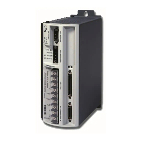
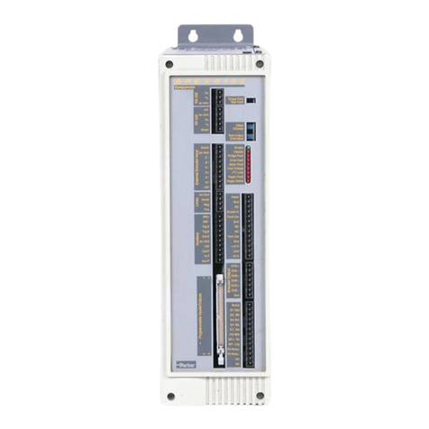
Product Type . . . . . . . . . . . . . . . . . . . . . Aries AR-04PE, -08PE, and -13PE Drives
ACR9030 and ACR9040 Controllers
The above product complies with the requirements of directives EMC Directive 89/336/EEC,
Low Voltage Directive 73/23/EEC, and CE Marking Directive 93/68/EEC, provided the installation
requirements described in the Aries EPL Hardware Installation Guide are met, and there are no
special requirements of the installation and operating environment so that the application may be
considered typical.
The above equipment conforms with the protection requirements of Council Directive
89/336/EEC as amended by Directive 92/31/EEC on the approximation of the laws of the
Member States relating to Electromagnetic Compatibility when installed, operated, and
maintained as intended. Also, the above equipment conforms with the requirements of
Council Directive 73/23/EEC (Low Voltage Directive) as amended by Directive 93/68/EEC
(CE Marking Directive), when installed, operated, and maintained as intended.
In accordance with IEC 61800-3:1997 (adjustable-speed electrical power drive systems) this
product is of the restricted sales distribution class which meets the needs of an industrial
environment when installed as directed. However, further measures may need to be taken for
use of the product in a domestic environment.
The installation requirements are detailed in the Information supplied with the equipment. The
equipment is sold only to competent system builders.
Quick Reference Guide
Aries AR-04PE, -08PE, and -13PE Servo Drives
ACR9030 and ACR9040 Controllers
ETHERNET
Powerlink
Aries EPL Drive ACR EPL Controller
To additional
Aries EPL Drive
Flag
Number
Parameter
Number
Controller Flags & Parameters
Control Flags
Start Network
Reset Network
Status Flags
EPL Controller Installed
Network Operational
Network Start Failed
EPL Node Failure
EPLD Stream OPEN
EPLD Stream Disconnected
EPL Drive(s) Enabled
Insufficient Period
Starting Network
Resetting Network
Opening EPLD Stream
16640
16641
16648
16649
16650
16651
16652
16653
16654
16655
16656
16657
16660
P37376
P37632*
P37634*
P37635*
P37384
P37385
P37386
P37387
P37388
P37389
EPL Network Control
Number of CNs (default 1; range 0–15)†
Node ID EPLD0 (default 1; range 1–99)†
Drive Mode EPLD0
TCP/IP Port Number EPLD0
EPL Network Status
Network State
Non-Operating Nodes Bit Reports
EPL Operation Error Code (0 = no error)
EPLD object OPENed (-1 = none)
OPENed EPLD Device Number
Operational Duration in Seconds
† Set by user
*For higher numbered EPLDs, work from EPLD0 and
add n x 16 to each parameter number
http://www.parkermotion.com
Compliance
UL, cUL Recognized Component, 508c
EPL Status LED
Drive Status LEDs
Axis Status LEDs
Address Switches
Ethernet Status LEDs
EPL Network Status LED
AC Power
Status LED
CANopen Status LED
ETHERNET
Powerlink
Drive I/O Connector EPL/Ethernet Connector
NOTE: A box surrounding the pins
indicates a requirement for twisted-
pair wiring.
•
•
•
Warning!
You must connect the drive’s protective conductor
terminal, marked with the earth symbol , to a reliable
system Protective Earth.
The drive’s connector strip terminals are at hazardous
voltages when power is applied to the drive, and up to
several minutes after power is removed. Lower voltages
may still be present for several minutes after power is
removed.
During normal operation, these high voltage terminals
must not be accessible to the user.
Signal Pin
Drive Output Power Connector
MOTOR
BK
BK
W
V
U
Motor Brake Relay
Motor Brake Relay
Motor Safety Earth
Motor Phase
Motor Phase
Motor Phase
Power Supply
Fuse Information
120/240 VAC, 50-60Hz, single phase
RX+ 1
RX– 2
TX+ 3
Not used 4
Not used 5
TX– 6
Not used 7
Not used 8
Signal Pin
Motor Feedback Connector
Signal Pin
*When using the SinCos protocol, pins
9 and 13 require twisted pair wiring.
Drive Status LEDs
Drive Enabled
Off
Yellow (flashes in Regen)
Yellow/Green (alternating)
Drive Disabled
Off
Yellow
Yellow
Yellow & 1 Green flash
Yellow & 2 Green flashes
Yellow & 3 Green flashes
Yellow & 4 Green flashes
Green
Green
Green
Red
Off
Red
Red
Red
Red
Red
Enabled
Regeneration active
Autorun mode
No faults, or Ethernet boot (8 sec)
Motor control boot (4 sec)
No bridge power
Bridge fault
Feedback fault
Thermal fault
Other fault
LED State
—
Left
Right What it means
Controller & Drive Ethernet Status LEDs
Ethernet Link/Activity
Ethernet Speed
Off
Yellow
Yellow, flashing
Off
Green
No Ethernet link detected
Ethernet link established;
no activity
Ethernet link established
and active
Ethernet 10Mbps
Ethernet 100Mbps
LED
State What it means
Drive EPL Status LEDs
Off
Off/Green (alternating, 50 ms)
Red/Green (alternating, 50 ms)
Green, 1 flash
Green, 2 flashes
Green, 3 flashes
Green, constant
Red/Green (alternating, 200 ms)
Powering up, searching for Ethernet
Standard Ethernet mode, no error
Standard Ethernet mode, EPL error
Waiting for configuration (followed by
Start of Cycle frame)
Waiting for configuration to complete
Ready to operate in EPL mode
EPL mode
Not participating in frame exchange,
but observing EPL communications
LED
State What it means
Drive has no internal fuses. For safety, you
must provide a fuse in each AC input line.
See installation guide for complete information.
Controller has one accessible fuse by the AC
power connector. 250 VAC, 2.5A, TD, 5x20 mm.
See installation guide for complete information.
Factory installed jumpers
C1 to L1
C2 to L2
Remove jumpers to use separate control
and motor mains AC power input.
R+
R-
C2
C1
L2
L1
Protective Earth GND
Control Input Power
Control Input Power
External Regeneration Resistor
Motor Input Power
Motor Input Power
Drive Mains Power Connector
Ethernet Cable: Use braid over foil twisted-pair
wiring (straight or crossover).
Controller CANopen Status LEDs
Green, flickering
Green, 1 flash
Green, blinking
Green, constant
Red, 1 flash
Red, flickering
Red, 2 flashes
Red, 3 flashes
Red, constant
Off
AutoBaud detection is in progress, or LSS services are
in progress (alternately flickering with red LED)
Stopped—Device is in the stopped state
Pre-operational—Device is in the pre-operational state
Operational—Device is in the operational state
Warning Limit Reached—At least one of the error
counters of the CAN controller has reached or
exceeded the warning level (too many error frames)
AutoBaud detection is in progress, or LSS services are
in progress
A guard event (NMT-slave or NMT-master) or a
heartbeat event (heartbeat consumer) has occurred
SYNC message has not been received within the
configured communication cycle period time out
(see Object Dictionary Entry 0x1006)
BUS off—CAN controller is bus off
Reset—controller is executing a reset
LED State
What it means
Axis disabled, no fault
Axis enabled, no fault
Axis fault; motion on axis disabled
LED
State What it means
Controller Axis Status LEDs
Off
Green
Red
NOTE: LED illuminates red whenever the drive fault input
is activated.
Drive IP Address Switches
Set IP address/node ID with drive’s rotary decimal switches.
Ex: set 14 by rotating x10 switch to 1 and x1 switch to 4 (valid
range is 01 to 99; 00 not valid). IP addresses are 192.168.100.xx,
with xx being drive’s switch setting.
Controller EPL Network Status LEDs
Off
Green
Flickering
1 flash
2 flashes
3 flashes
Constant
Blinking
Reset or not active—MN is off, initializing, or
in reset state
Basic Ethernet—Node operating as a basic
Ethernet device, not EPL
Pre-Operational 1—MN asking node status &
configuring CNs; full EPL cycles not started
Pre-Operational 2—Full EPL cycles started,
node confguration not finished, data ignored
Ready to operate—CN has responded to
request from MN; exchanged data ignored
Operational—Network exchanging valid data
Stopped—Network has stopped
LED State
What it means
Red Indicates error state, obtained via P37386
0
1
2
3
4
5
6
7
8
9
0
1
2
3
4
5
6
7
8
9
EPL
Status
Drive
Status
Address
Switches
See front cover for controllerLED locations.
Input 0+ 1
Input 0– 14
Input 1+ 2
Input 1– 15
Input 2+ 3
Input 2– 16
High-Speed Input 4+ 4
High-Speed Input 4– 17
High-Speed Input 5+ 5
High-Speed Input 5– 18
High-Speed Input 6+ 6
High-Speed Input 6– 19
Input 3+ 7
Input 3– 20
Not used 8
Not used 21
Output 0+ 9
Output 0– 22
Output 1+ 10
Output 1– 23
Output 2+ 11
Output 2– 24
Output 3+ 12
Output 3– 25
Not used 13
ENC Z+/DATA+ 1
ENC Z–/DATA– 2
DGND 3
+5 VDC (250mA max) 4
+5 VDC (250mA max) 5
DGND 6
ENC A–/SIN– 7
ENC A+/SIN+ 8
Hall 1/SCLK+ *9
Thermal+ 10
Thermal– 15
ENC B–/COS– 11
ENC B+/COS+ 12
Hall 2/SCLK– *13
Hall 3 14
This manual suits for next models

4

Other Parker Servo Drive manuals

Parker Compax3 Fluid T40 Installation manual

Parker

Parker Compax3 Fluid T40 Installation manual

Parker P Series User manual

Parker

Parker P Series User manual

Parker PSD1-S User manual

Parker

Parker PSD1-S User manual

Parker OEM750 User manual

Parker

Parker OEM750 User manual

Parker Compumotor TQ10 User manual

Parker

Parker Compumotor TQ10 User manual

Parker FL20-CA Series User manual

Parker

Parker FL20-CA Series User manual

Parker Gemini GV Series User manual

Parker

Parker Gemini GV Series User manual

Parker F10 Series User manual

Parker

Parker F10 Series User manual

Parker Compax3 C3I20T11 User manual

Parker

Parker Compax3 C3I20T11 User manual

Parker K Series User manual

Parker

Parker K Series User manual

Parker P Series User manual

Parker

Parker P Series User manual

Parker FL20-S Series User manual

Parker

Parker FL20-S Series User manual

Parker FL-20-C Series User manual

Parker

Parker FL-20-C Series User manual

Parker PSD1-S User manual

Parker

Parker PSD1-S User manual

Parker PSD1-SW1200 User manual

Parker

Parker PSD1-SW1200 User manual

Parker Compax3 I10T10 User manual

Parker

Parker Compax3 I10T10 User manual

Parker Compumotor APEX615 Series User manual

Parker

Parker Compumotor APEX615 Series User manual

Parker Compax3S025V2 User manual

Parker

Parker Compax3S025V2 User manual

Parker PSD1 User manual

Parker

Parker PSD1 User manual

Parker 590C User manual

Parker

Parker 590C User manual

Parker ViX250AH User manual

Parker

Parker ViX250AH User manual

Parker NK Series User manual

Parker

Parker NK Series User manual

Parker 638 series User manual

Parker

Parker 638 series User manual

Parker Compax3 Fluid T40 User manual

Parker

Parker Compax3 Fluid T40 User manual

Popular Servo Drive manuals by other brands

Mitsubishi Electric Melservo-Jet HG-SNS Series user manual

Mitsubishi Electric

Mitsubishi Electric Melservo-Jet HG-SNS Series user manual

Vescent Photonics D2 Series manual

Vescent Photonics

Vescent Photonics D2 Series manual

Siemens MICROMASTER 6SE92 Getting started

Siemens

Siemens MICROMASTER 6SE92 Getting started

Acoms AS17 Technical note

Acoms

Acoms AS17 Technical note

Fastech Ezi-SERVO ST Operation manual

Fastech

Fastech Ezi-SERVO ST Operation manual

Overview Leto OVU00243 quick start guide

Overview

Overview Leto OVU00243 quick start guide

Hiwin D2 user manual

Hiwin

Hiwin D2 user manual

Danfoss VLT ISD 511 operating guide

Danfoss

Danfoss VLT ISD 511 operating guide

Leadshine HBS Series Hardware installation manual

Leadshine

Leadshine HBS Series Hardware installation manual

Allen-Bradley 2094-AC05-MP5 user manual

Allen-Bradley

Allen-Bradley 2094-AC05-MP5 user manual

Festo CMTT-AS S1 Series Description

Festo

Festo CMTT-AS S1 Series Description

WEG SCA06 user guide

WEG

WEG SCA06 user guide

Siemens sinamics V60 CPM60.1 user manual

Siemens

Siemens sinamics V60 CPM60.1 user manual

RHINO MOTION CONTROLS RMCS-2301 Installation Manual and Datasheet

RHINO MOTION CONTROLS

RHINO MOTION CONTROLS RMCS-2301 Installation Manual and Datasheet

Eaton NFX9000 Quick reference guide

Eaton

Eaton NFX9000 Quick reference guide

A-TS TECHNOLOGY RT20 user manual

A-TS TECHNOLOGY

A-TS TECHNOLOGY RT20 user manual

Moons' Applied Motion Products SV7-C Quick setup guide

Moons'

Moons' Applied Motion Products SV7-C Quick setup guide

OE Max Controls CSDJ Plus user manual

OE Max Controls

OE Max Controls CSDJ Plus user manual

manuals.online logo
manuals.online logoBrands
  • About & Mission
  • Contact us
  • Privacy Policy
  • Terms and Conditions

Copyright 2025 Manuals.Online. All Rights Reserved.