SSV RMG/938 User manual
Remote Maintenance Gateway
RMG/9
38
with eSOM/7210
First Steps
SSV Software Systems GmbH
Dünenweg 5
D-30419 Hannover
Phone: +49 (0)511/40 000-0
Fax: +49 (0)511/40 000-40
Document Revision: 1.0
Date: 2022-06-03

Remote Maintenance Gateway RMG/938 – First Steps
2
D oc u m e n t R e v i s i o n 1 . 0
CONTENT
1
INTRODUCTION ............................................................................................................... 3
1.1
Conventions ........................................................................................................................... 3
2
SAFET GUIDELINES ..................................................................................................... 4
3
REQUIRED EQUIPMENT ................................................................................................. 5
4
CONNECTIONS ................................................................................................................ 6
4.1
Ethernet Link .......................................................................................................................... 6
4.2
Serial Ports COM2 and COM3 ................................................................................................ 7
4.3
Power Suppl ......................................................................................................................... 8
5
OPERATION ..................................................................................................................... 9
5.1
Booting the RMG/938 ............................................................................................................ 9
5.2
Accessing the SSV/WebUI ...................................................................................................... 9
5.3
Accessing the SSV/WebUI with DHCP enabled ................................................................... 10
5.4
LAN1 Configuration .............................................................................................................. 12
5.5
Access via Telnet .................................................................................................................. 13
5.6
Access via FTP ...................................................................................................................... 14
5.7
Bluetooth Service Configuration ......................................................................................... 15
5.8
Node-RED Configuration ...................................................................................................... 16
6
TECHNICAL DATA ......................................................................................................... 18
7
PINOUT SCREW TERMINALS ....................................................................................... 18
8
LED FUNCTIONS ........................................................................................................... 19
9
HELPFUL LITERATURE ................................................................................................ 20
CONTACT ............................................................................................................................. 20
DOCUMENT HISTOR ......................................................................................................... 20
Remote Maintenance Gateway RMG/938 – First Steps
D o c u m e n t R e v i s i o n 1 . 0
3
1 INTRODUCTION
This documentation gives an overview about the initial operation and the first steps of use
with the RMG/938.
IMPORTANT!
You will need further e uipment to operate the RMG/938. Please refer to chapter 3.
1.1 Conventions
Convention
Usage
bold
Impor
tant terms
monospace
Filenames, Pathnames, program code, command lines
Table 1: Conventions used in this document

Remote Maintenance Gateway RMG/938 – First Steps
4
D o c u m e n t R e v i s i o n 1 . 0
2 SAFETY GUIDELINES
Please read the ollowing sa ety guidelines care ully! In case o property or personal
damage by not paying attention to this manual and/or by incorrect handling, we do not
assume liability. In such cases any warranty claim expires.
• The power supply should be in immediate proximity to the device.
• The power supply must provide a stable output voltage between 11 – 28 VDC. The out-
put power should be at least 2.5 W.
• Please pay attention that the power cord or other cables are not s ueezed or damaged
in any way when you set up the device.
• Do NOT turn on the power supply while connecting any cables, especially the power
cables. This could cause damaged device components! First connect the cables and
THEN turn the power supply on.
• The installation of the device should be done only by ualified personnel.
• Discharge yourself electrostatic before you work with the device, e.g. by touching a
heater of metal, to avoid damages.
• Stay grounded while working with the device to avoid damage through electrostatic
discharge.
• The case of the device should be opened only by ualified personnel.

Remote Maintenance Gateway RMG/938 – First Steps
D o c u m e n t R e v i s i o n 1 . 0
5
3 REQUIRED EQUIPMENT
To operate the RMG/938 the following hardware is re uired:
• 24 VDC power supply
• One Ethernet cross-over cable or two Ethernet patch cables and a switch.
To configure the RMG/938 a computer with the following features is re uired:
• Windows 7 or higher
• Web browser (e.g. Firefox, Chrome)
• Telnet/SSH client (e.g. TeraTerm)
• FTP client (e.g. FileZilla)
• 10/100 Mbps Ethernet network controller and TCP/IP configuration
Remote Maintenance Gateway RMG/938 – First Steps
6
D o c u m e n t R e v i s i o n 1 . 0
4 CONNECTIONS
For a uick and easy start with the RMG/938 there are a few cable connections necessary.
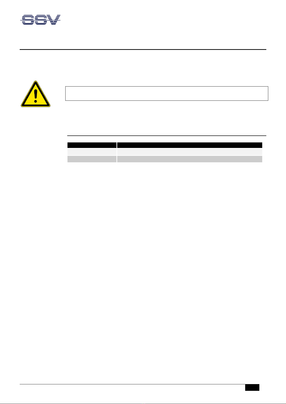
4.1 Ethernet Link
The Ethernet link between the PC and LAN1 of the RMG/938 can be made on two ways:
• Direct with an Ethernet cross-over cable like shown in ig. 1.
• With two standard Ethernet patch cables over a hub or switch like shown in ig. 2.
Figure 1: Ethernet link with cross-over cable
Please note:
For the Ethernet connection in ig. 1 it is re uired to use a cross-over cable. Do not
use an ordinary patch cable. Both types of cables are in most cases visual indistin-
guishable. But the internal wiring is fully different. Mixing up these types of cables
leads to LAN errors. Hence pay attention to the label of the cable or packing.
Figure 2: Ethernet link with hub or switch
The IP address of the LAN1 interface is ex-factory set to 192.168.0.126.
Remote Maintenance Gateway RMG/938 – First Steps
D o c u m e n t R e v i s i o n 1 . 0
7
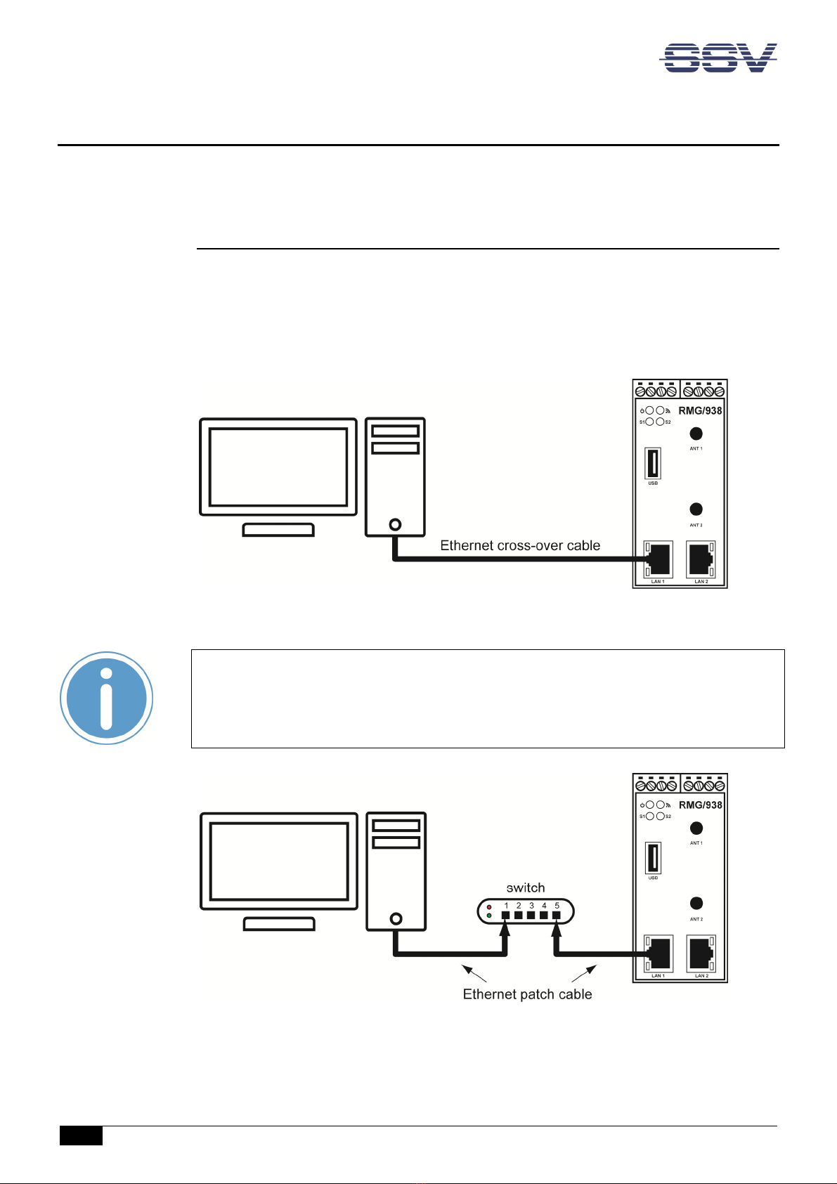
4.2 Serial Ports COM2 and COM3
You can create an RS485 serial link on port COM2 and COM3 of the RMG/938.
An RS232 serial link is only possible on port COM3.
Figure 3: Serial links on COM2 and COM3
Terminal
Signal
A1
COM2 RS485 Serial Port RX /TX+
A2
COM2 RS485 Serial Port RX /TX
-
B4
Signal Ground
Table 2: Screw terminals COM2
Terminal
Signal
B2
COM3 Serial Port: TXD (RS232), RX/TX
-
(RS485)
B3
COM3 Serial Port: RXD (RS232), RX/TX+ (RS485)
B4
Signal Ground
Table 3: Screw terminals COM3
Please note:
The RS485 (officially called TIA/EIA-485-A) connection between your RMG/938 and
the field devices needs termination resistors on both ends for proper operation. The
RMG/938 does not o er internal termination resistors. Please make sure, that the
RS485 cable connection is e uipped with external termination resistors.
Remote Maintenance Gateway RMG/938 – First Steps
8
D o c u m e n t R e v i s i o n 1 . 0
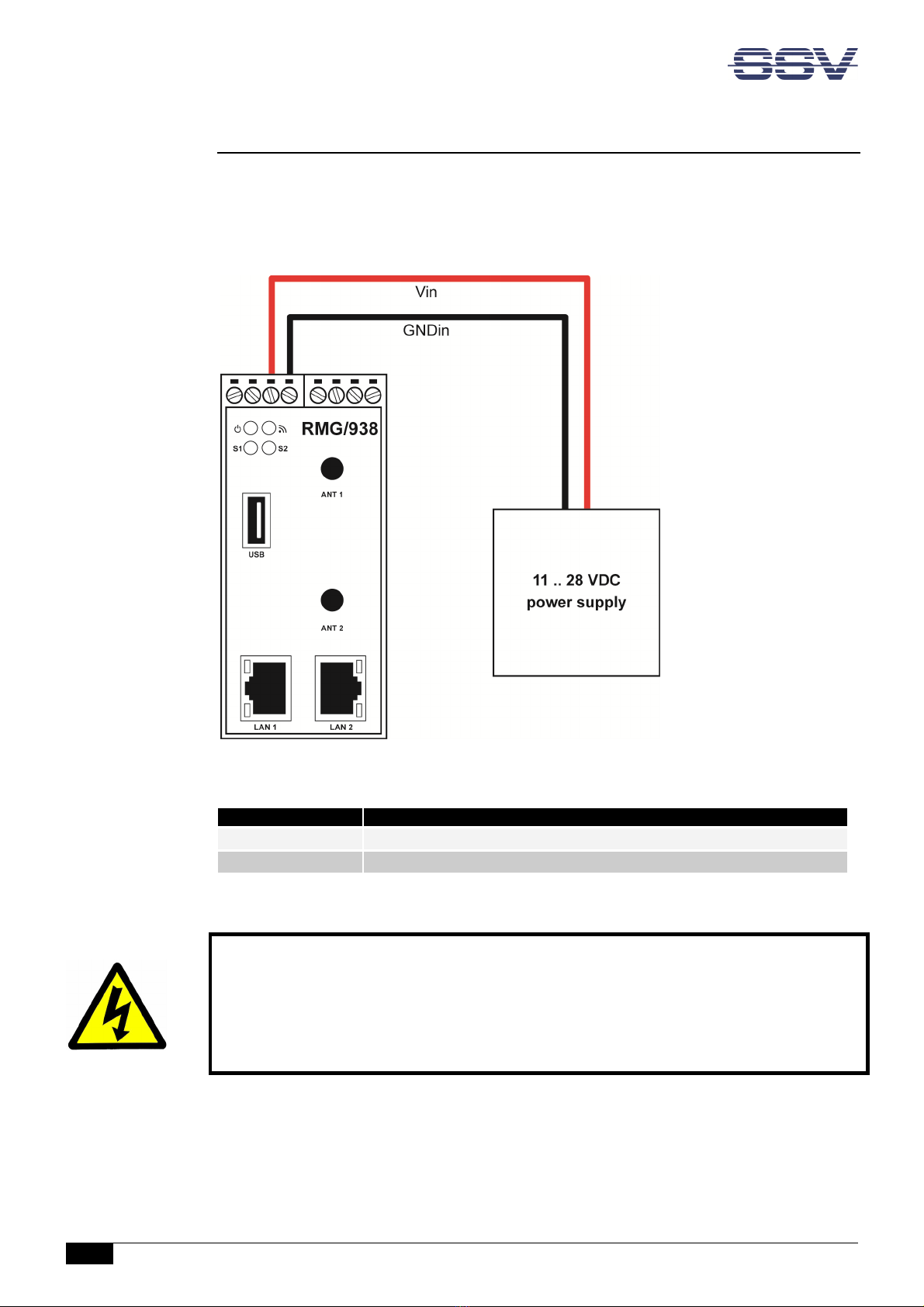
4.3 Power Supply
The RMG/938 needs a supply voltage of 11 – 28 VDC to work.
Connect the cables of an appropriate power supply like shown in ig. 4.
Figure 4: Power supply or the RMG/938
Terminal
Signal
A3
Vin (11 .. 28 VDC)
A4
GNDin
Table 4: Screw terminal power
CAUTION!
Providing the RMG/938 with a higher voltage than the regular 11 – 28 VDC could cause
damaged device components!
Do NOT turn on the power supply while connecting it with the RMG/938. This could cause
damaged device components! First connect the power supply and THEN turn it on.

Remote Maintenance Gateway RMG/938 – First Steps
D o c u m e n t R e v i s i o n 1 . 0
9
5 OPERATION
5.1 ooting the RMG/938
Just power up the RMG/938 and the boot process starts immediately. This may take up to
one minute.
5.2 Accessing the SSV/WebUI
To open the login page of the SSV/WebUI enter the ex-factory IP address and port number
of LAN1 of the RMG/938 manually in a web browser:
https://192.168.0.126:7777
Enter your username and password and click on [Login]. Both username and password can
be found on the nameplate of the RMG/938.
Figure 5: Login page o the SSV/WebUI

Remote Maintenance Gateway RMG/938 – First Steps
10
D o c u m e n t R e v i s i o n 1 . 0
5.3 Accessing the SSV/WebUI with DHCP enabled
If the automatic IP address configuration of LAN1 via DHCP is enabled, you have to check
the assigned IP address, which is necessary to access the RMG/938 via a Telnet client or a
web browser.
Therefore open in Windows Control Panel > Network and Internet > View network com-
puters and devices. The RMG/938 should show up in this list.
Figure 6: Selecting the RMG/938
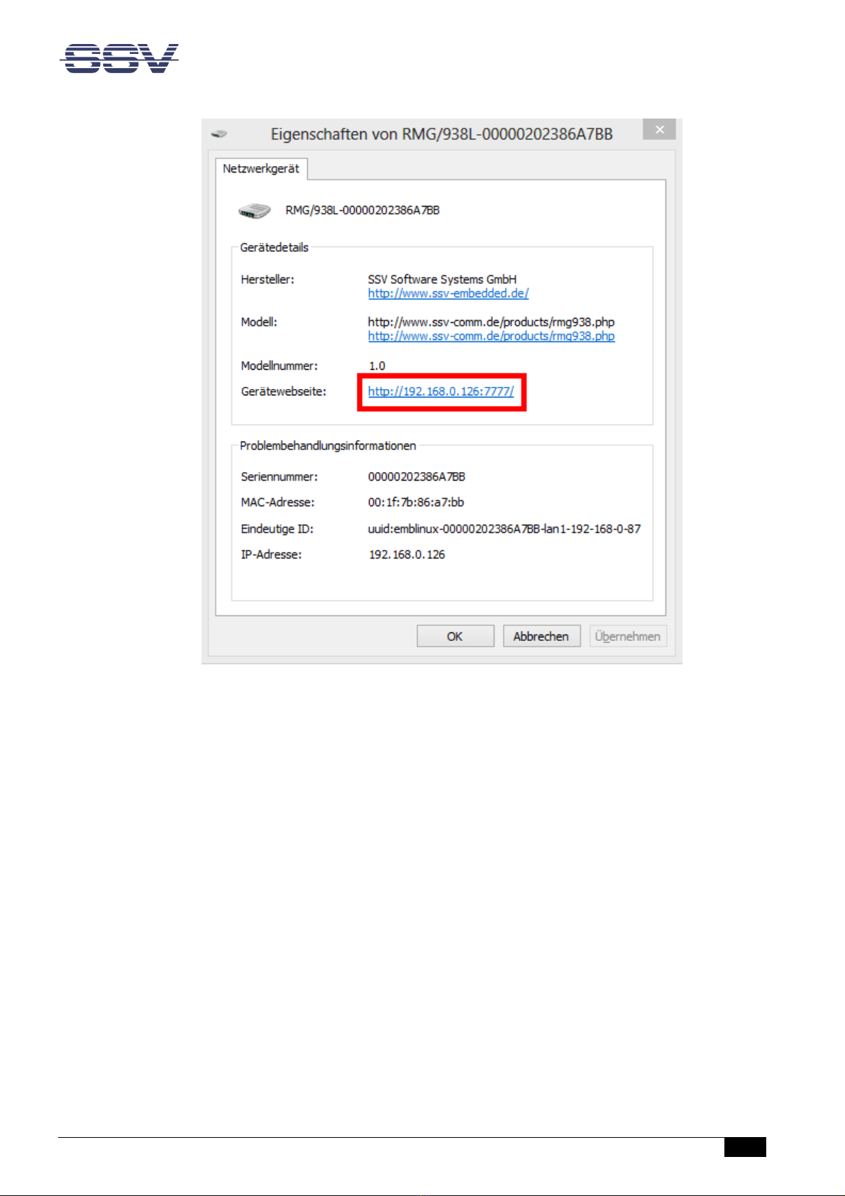
Just right-click on the RMG/938 to open the properties dialog, where you can see the cur-
rent IP address of the RMG/938 like shown in ig. 7.
A double-click on the RMG/938 opens the SSV/WebUI in a web browser.
Please note:
To access the SSV/WebUI, it is important to add the port number 7777 to the cur-
rent IP address of the RMG/938, e.g.: http://192.168.0.126:7777!
Remote Maintenance Gateway RMG/938 – First Steps
D o c u m e n t R e v i s i o n 1 . 0
11
Figure 7: The properties dialog shows the current IP address
Now you are able to access the RMG/938 via a Telnet client or a web browser.
RMG/938 – First Steps
12
D o c u m e n t R e v i s i o n 1 . 0
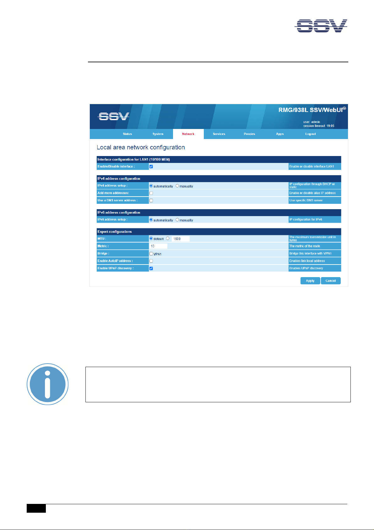
5.4 LAN1 Configuration
The IP address of the LAN1 interface is ex-factory set to 192.168.0.126.
To configure the LAN1 settings choose from the menu Network > LAN1.
Figure 8: LAN1 settings
To enable the automatic IP address assignment via DHCP follow these steps:
1. In the section IP address con iguration enable the radio button automatically.
2. Click on [Apply].
Please note:
After DHCP was enabled, it is necessary to re-log into the SSV/WebUI with the new
assigned IP address of LAN1. Please refer to chapter 5.3 to find out the current IP
address.

Remote Maintenance Gateway RMG/938 – First Steps
D o c u m e n t R e v i s i o n 1 . 0
13
5.5 Access via Telnet
Please note:
The Telnet server must be enabled via the SSV/WebUI. Therefore choose from the
menu Services > General, enable the checkbox in the line Telnet server and click on
[Apply].
To access the RMG/938 via Telnet open a Telnet client program (like TeraTerm) on your
host PC and enter the current IP address of the RMG/938 to activate a Telnet session.
In the upcoming Telnet window you can enter your login data.
Figure 9: Accessing the RMG/938 via Telnet client
Remote Maintenance Gateway RMG/938 – First Steps
14
D o c u m e n t R e v i s i o n 1 . 0
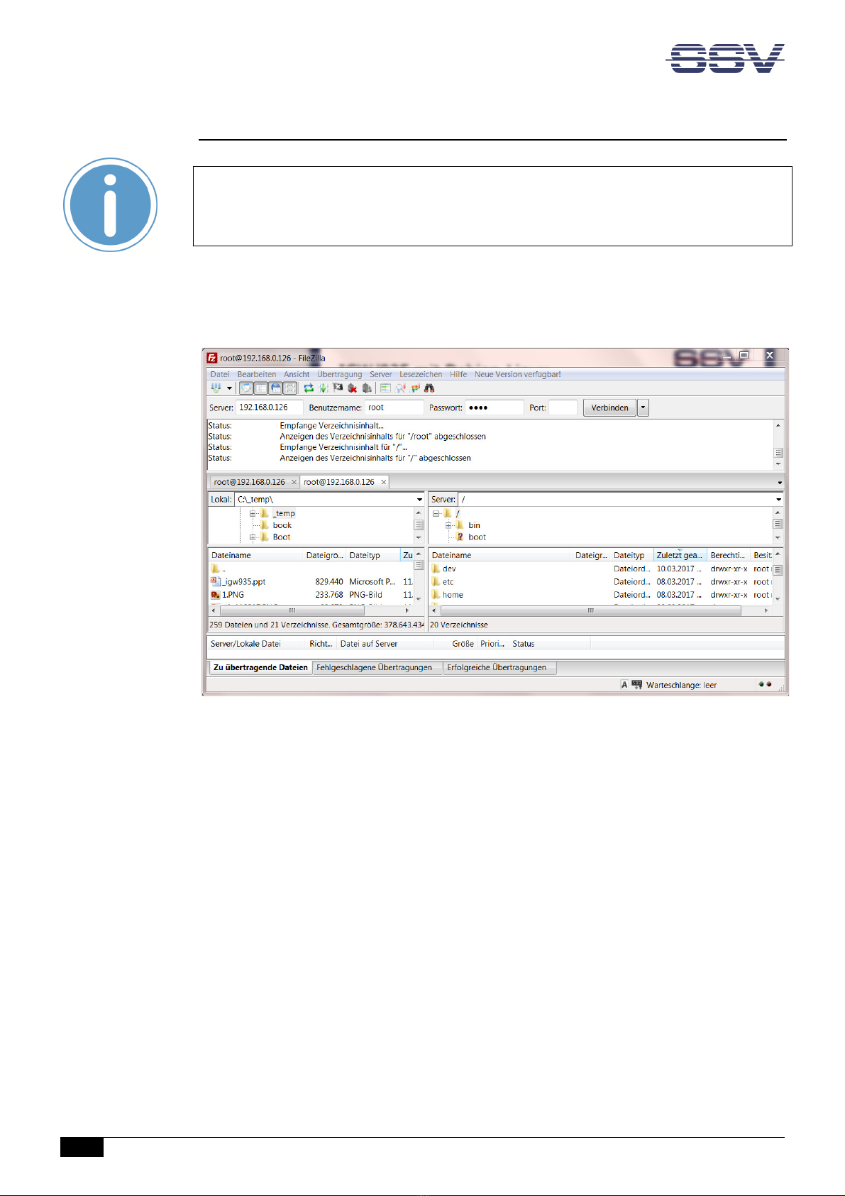
5.6 Access via FTP
Please note:
The FTP server must be enabled via the SSV/WebUI. Therefore choose from the
menu Services > General, enable the checkbox in the line FTP server and click on
[Apply].
The RMG/938 comes with a pre-installed FTP server, which allows the file transfer via
Ethernet between a PC and the RMG/938. To access the RMG/938 via FTP use an FTP client
like e.g. FileZilla.
Figure 10: FileZilla as FTP client to access the FTP server
Use for the FTP login the current IP address of the RMG/938. After the login you have FTP
read/write permission in the file system.
We recommend to use the directory /media/data to store own files.

Remote Maintenance Gateway RMG/938 – First Steps
D o c u m e n t R e v i s i o n 1 . 0
15
5.7 luetooth Service Configuration
To configure the Bluetooth settings choose from the menu Network > Bluetooth.
Figure 11: Bluetooth settings
To enable the Bluetooth interface follow these steps:
1. In the section General con iguration enable the checkbox.
2. Click on [Apply].
A green arrow on the right side indicates that Bluetooth is enabled.

Remote Maintenance Gateway RMG/938 – First Steps
16
D o c u m e n t R e v i s i o n 1 . 0
5.8 Node-RED Configuration
To configure Node-RED click in the menu on Apps > Node-RED.
Figure 12: Node-RED settings
To enable Node-RED follow these steps:
1. In the section General con iguration enable the checkbox.
2. Click on [Apply].
A green arrow on the right side indicates that Node-RED is enabled.
After a few seconds the Node-RED editor can be opened with the hyperlink node-red on
the right side.
Alternatively you can enter the RMG/938’s IP address with the port number 1880 directly in
the address bar of the web browser, e.g. https://<IP address>:1880.
Remote Maintenance Gateway RMG/938 – First Steps
D o c u m e n t R e v i s i o n 1 . 0
17
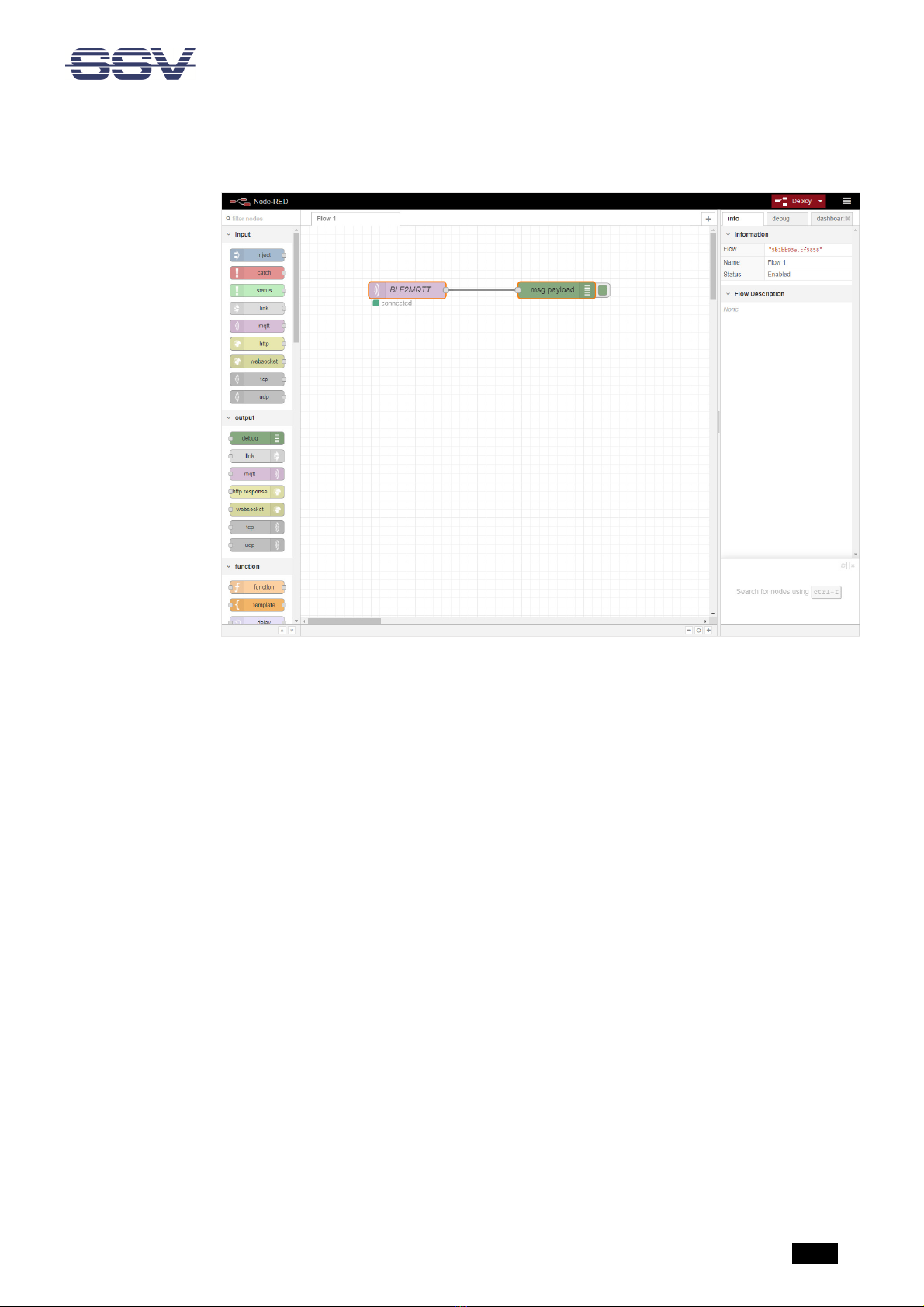
The Node-RED editor offers a simple flow to display incoming Bluetooth data in the debug
window on the right side of the workspace.
Figure 13: Node-RED editor

Remote Maintenance Gateway RMG/938 – First Steps
18
D o c u m e n t R e v i s i o n 1 . 0
6 TECHNICAL DATA
Supply voltage ................................................................................. 11 – 28 VDC
Weight ..................................................................................................... < 270 g
Mechanical Dimensions (LxWxH) ............................. 112 mm x 45 mm x 100 mm
Temperature range ........................................................................... 0° C – 60° C
Rel. air himudity .................................................................................. max. 85%
7 PINOUT SCREW TERMINALS
Table 6 shows the pinout of the screw terminals of the RMG/938.
Terminal
Signal
A1
COM2 Serial Port: RS485 RX/TX+
A2
COM2 Serial Port: RS485 RX/TX
-
A3
Vin (11 .. 28 VDC)
A4
Power Ground
B1
---
B2
COM3 Serial Port: TXD (RS232), RX/TX
-
(RS485)
B3
COM3 Serial Port: RXD (RS232), RX/TX+ (RS48
5)
B4
Signal Ground
Table 5: Pinout o the screw terminals
Please note:
The RS485 (officially called TIA/EIA-485-A) connection between your RMG/938 and
the field devices needs termination resistors on both ends for proper operation. The
RMG/938 does not o er internal termination resistors. Please make sure, that the
RS485 cable connection is e uipped with external termination resistors.

Remote Maintenance Gateway RMG/938 – First Steps
D o c u m e n t R e v i s i o n 1 . 0
19
8 LED FUNCTIONS
L D
Description
Off
Flash
On
Power
No Power
---
Power On
N/A
---
---
---
S1
System
Not ready
Booting
Re
ady
S2
VPN state
Off
Connecting
Ready
Table 1: LED unctions
The LED S2 shows the VPN connection state by different flashing. The following table de-
scribes the functions of the particular LED signals.
On Time
Off Time
Description
Permanent
---
VPN connected
1
s
1
s
VPN
-
client tries connecting the VPN
-
server
---
Permanent
Unknown state, VPN disconnected
Table 2: LED S2 unctions

RMG/938 – First Steps
20
D o c u m e n t R e v i s i o n 1 . 0
9 HELPFUL LITERATURE
• https://nodered.org
CONTACT
SSV So tware Systems GmbH
Dünenweg 5
D-30419 Hannover
Phone: +49 (0)511/40 000-0
Fax: +49 (0)511/40 000-40
Email: [email protected]
Internet: www.ssv-embedded.de
Forum: www.ssv-comm.de/forum
Wiki: mewi.ssv-embedded.de
Social: https://www.linkedin.com/company/ssv-software-systems
DOCUMENT HISTORY
Revision
Date
Remarks
Name
Review
1.0 2022-06-03 First version WBU ENE
The content of this document can change any time without an
nouncement. There is taken over no guaran-
tee for the accuracy of the statements. The user assumes the en
tire risk as to the accuracy and the use of
this document. Information in this docu
ment is provided ‘as is’ without warranty of any kind. Some names
within this document can be trademarks of their respective holders.
© 2022 SSV SOFTWARE SYSTEMS GMBH. All rights reserved.
Table of contents
Other SSV Gateway manuals

SSV
SSV IGW/925 Installation and user guide

SSV
SSV IGW/922 Application guide

SSV
SSV IGW/922 User manual

SSV
SSV IGW/936A User guide

SSV
SSV IGW/920 User manual

SSV
SSV IGW/100 Application guide

SSV
SSV IGW/935 User manual

SSV
SSV IGW/925-W Application guide

SSV
SSV IGW/935 User manual

SSV
SSV RMG/941 Series Application guide


Popular Gateway manuals by other brands


Edgewater Networks
Edgewater Networks EdgeMarc 4552 quick start guide

ZyXEL Communications
ZyXEL Communications P-794H user guide

RTA
RTA 460ECBM-NNA1 Product user guide

Dell
Dell Dell Edge Gateway 3002 Specifications

Bivocom
Bivocom TG452 Series user guide

Edgewater Networks
Edgewater Networks 4610W Hardware installation guide