SSV IGW/935 User manual
WEB APPLICATION GATEWAY
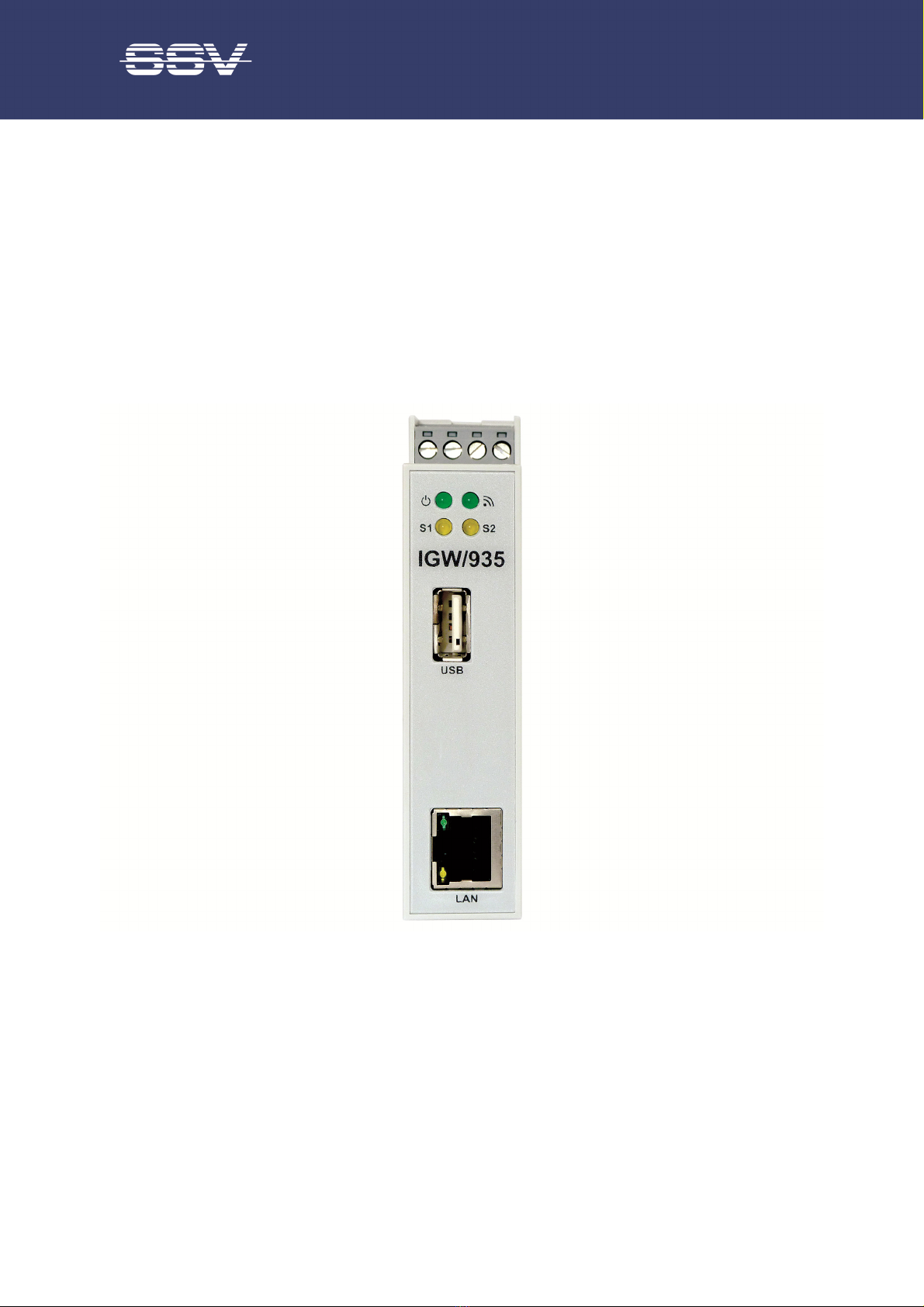
IGW/935
with eSOM/3517
First Steps
SSV SOFTWARE SYSTEMS Document Revision 1.4 // 2023-07-11

Introduction
2
IGW/935 //
First Steps
CONTENT
1
INTRODUCTION .................................................................................................... 3
1.1
Checklist .................................................................................................................... 3
1.2
Required Equipment ................................................................................................. 3
1.3
Document Conventions ............................................................................................. 3
2
SAFETY GUIDELINES .......................................................................................... 4
3
CONNECTIONS ..................................................................................................... 5
3.1
Ethernet Link ............................................................................................................. 5
3.2
RS485 Seri l Link ....................................................................................................... 6
3.3
Power Supply ............................................................................................................. 7
4
OPERATION .......................................................................................................... 8
4.1
Accessing the SSV/WebUI ......................................................................................... 8
4.2
Accessing the SSV/WebUI with DHCP en bled ......................................................... 9
4.3
Firew ll Configur tion ............................................................................................. 11
4.4
LAN Configur tion ................................................................................................... 12
4.5
Accessing the SSV/WebUI Demo P ge .................................................................... 13
4.6
Access vi Telnet ..................................................................................................... 14
4.7
Access vi FTP .......................................................................................................... 15
5
SOFTWARE EXPANSIONS & APPS .................................................................. 17
6
TROUBLE SHOOTING IP ADDRESS PROBLE S ............................................ 17
7
TECHNICAL INFOR ATION .............................................................................. 18
7.1
Technic l D t ......................................................................................................... 18
7.2
Pinout Screw Termin ls ........................................................................................... 18
8
HELPFUL LITERATURE ..................................................................................... 19
CONTACT ................................................................................................................. 19
DOCU ENT HISTORY ............................................................................................. 19

Introduction
IGW/935 // First Steps
3
1 INTRODUCTION
This documentation gives you an overview about the initial operation and the first steps of use with
the Web Application Gateway IGW/935
1.1 Checklist
Compare the content of your IGW/935 package with the checklist below If any item is missing or ap-
pears to be damaged, please contact SSV
Web Application Gateway IGW/935 with eSOM/3517
Documentation
Plu -in power supply
CD-ROM for eSOM/3517
Screwdriver
1.2 Required Equipment
To operate the IGW/935 the following hardware is required:
One Ethernet cross-over cable or two Ethernet patch cables and a switch.
To configure the IGW/935 a PC with the following features is required:
Windows 7 or hi her
Web browser (e. . Firefox, Chrome)
Telnet/SSH client (e. . TeraTerm)
FTP client (e. . FileZilla)
10/100 Mbps Ethernet network controller and TCP/IP confi uration
CD-ROM drive
1.3 Document Conventions
Convention
Usage
bold
Important terms
monospace
Filenames, Pathnames, program code, command lines
Table 1: Conventions used in this document

Safety Guidelines
4
IGW/935 //
First Steps
2 SAFETY GUIDELINES
Please read the followin safety uidelines carefully! In case of property or personal dama e by
not payin attention to this document and/or by incorrect handlin , we do not assume liability. In
such cases any warranty claim expires.
ATTENTION!
OBSERVE PRECAUTIONS FOR HANDLING – ELECTROSTATIC SENSITIVE DEVICE!
The power supply should be in immediate proximity to the device.
The power supply must provide a stable output volta e at 12 .. 24 VDC ±10%. The output
power should be at least 10 W.
Please pay attention that the power cord or other cables are not squeezed or dama ed in
any way when you set up the device.
Do NOT turn on the power supply while connectin any cables, especially the power cables.
This could cause dama ed device components! First connect the cables and THEN turn the
power supply on.
The installation of the device should be done only by qualified personnel.
Dischar e yourself electrostatic before you work with the device, e. . by touchin a heater
of metal, to avoid dama es.
Stay rounded while workin with the device to avoid dama e throu h electrostatic dis-
char e.
The case of the device should be opened only by qualified personnel.
Connections
IGW/935 // First Steps
5
3 CONNECTIONS
For a quick and easy start with the IGW/935 there are a few cable connections necessary The follow-
ing chapters describe how these connections have to be made
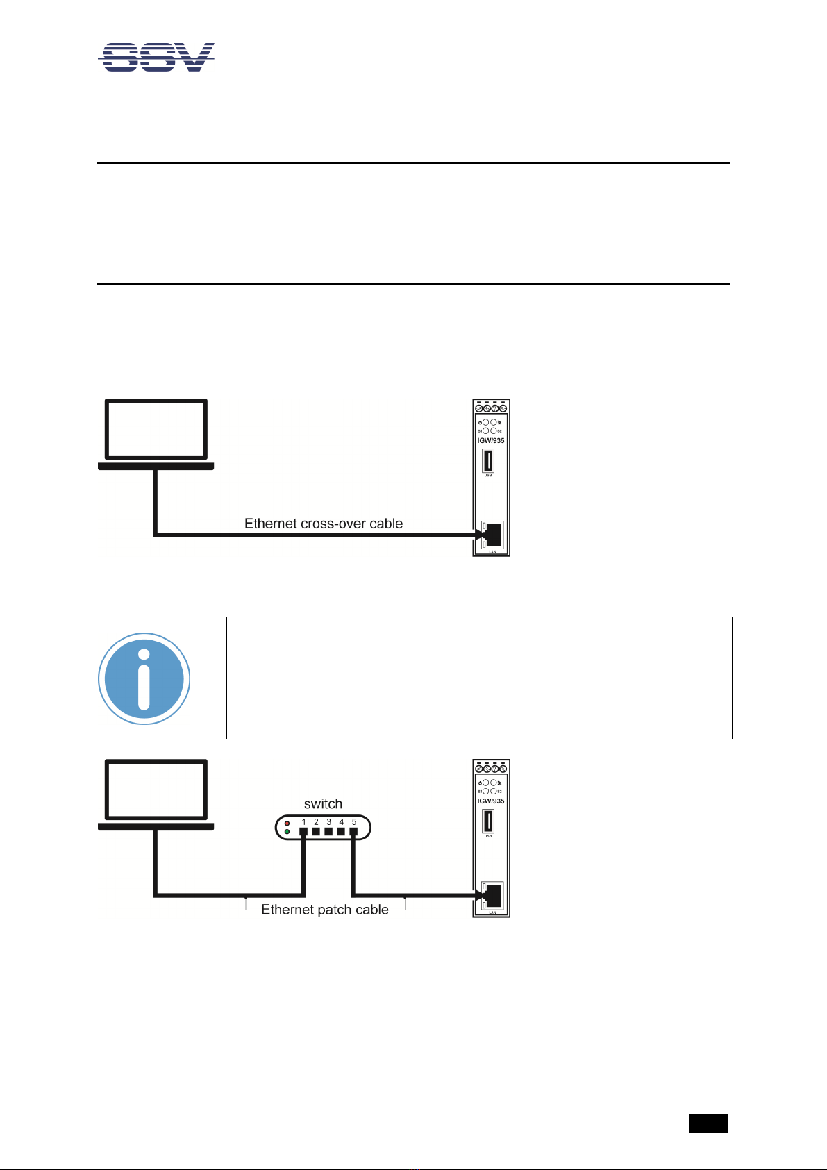
3.1 Ethernet Link
The Ethernet link between the PC and LAN1 of the IGW/935 can be made on two ways:
Direct with an Ethernet cross-over cable like shown in fi ure 1
With two standard Ethernet patch cables over a hub or switch like shown in fi ure 2
Fi ure 1: Ethernet link with cross-over cable
Please note:
For the Ethernet connection in fi ure 1 it is required to use a cross-over cable
Do not use an ordinary patch cable Both types of cables are in most cases visu-
al indistinguishable But the internal wiring is fully different Mixing up these
types of cables leads to LAN errors Hence pay attention to the label of the ca-
ble or packing
Fi ure 2: Ethernet link with hub or switch
The IP address of the LAN1 interface is ex-factory set to 192.168.0.126
Connections
6
IGW/935 //
First Steps
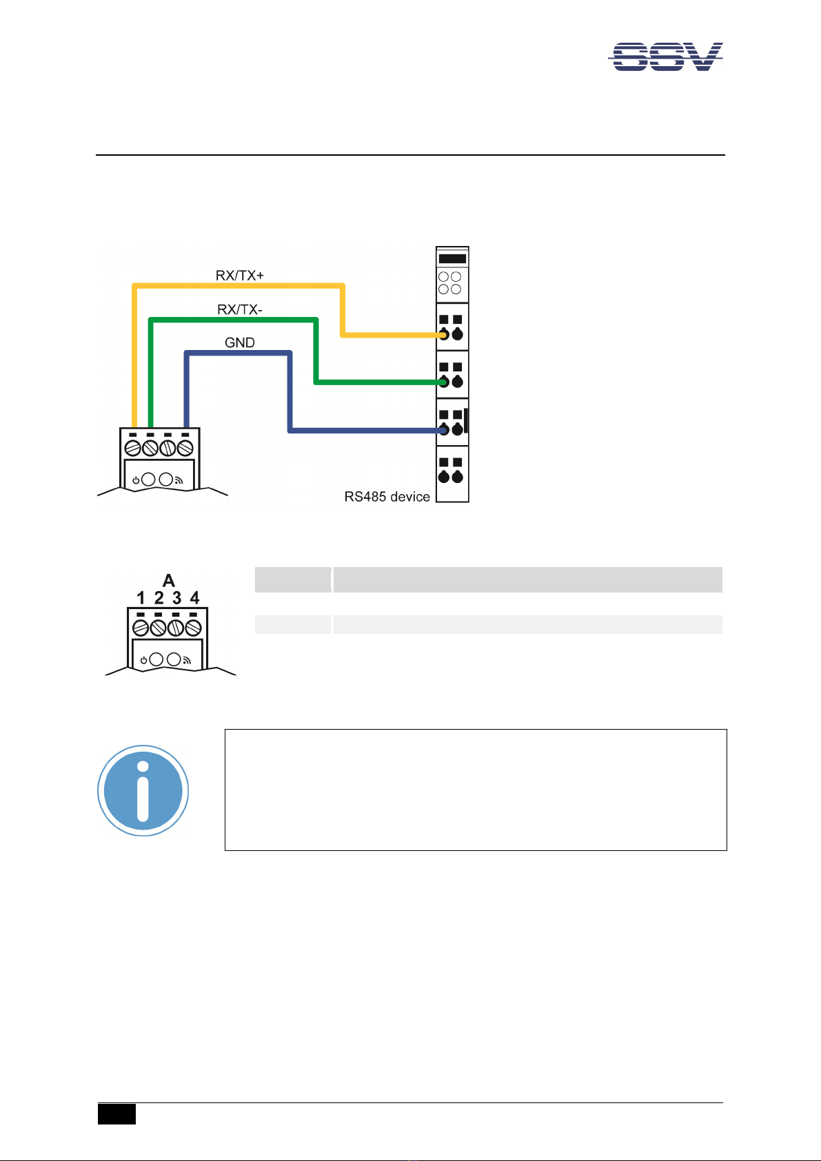
3.2 RS485 Seri l Link
To create an RS485 serial link on port COM1 of the Fehler! Verwenden Sie die Re isterkarte 'Start',
um Produktname dem Text zuzuweisen, der hier an ezei t werden soll. connect an RS485 device
like shown in fi ure 3
Fi ure 3: Layout of IGW/935
Terminal
Signal
A1
COM2 Serial Port: RS485 RX/TX+
A2
COM2 Serial Port: RS485 RX/TX
-
A4
Vin
-
Table 2: Pinout screw terminals COM1
Please note:
The RS485 (officially called TIA/EIA-485-A) connection between your IGW/935
and the field devices needs termination resistors on both ends for proper oper-
ation The IGW/935 does not offer internal termination resistors Please make
sure, that the RS485 cable connection is equipped with external termination re-
sistors.

Connections
IGW/935 // First Steps
7
3.3 Power Supply
The IGW/935 needs a supply voltage of 12 24 VDC ±10% to work
Connect the cables of an appropriate power supply to provide the system with the necessary power
like shown in fi ure 5
Fi ure 4: Power supply for the IGW/935
Terminal
Signal
A
3
Vin
+
(1
2
2
4
VDC
±10%
)
A
4
V
in
-
Table 3: Pinout screw terminals power
CAUTION!
Providing the IGW/935 with a higher voltage than the regular 12 24 VDC ±10%
could cause damaged device components!
Do NOT turn on the power supply while connecting it with the IGW/935 This
could cause damaged device components! First connect the power supply and
THEN turn it on.

Operation
8
IGW/935 //
First Steps
4 OPERATION
Just power up the IGW/935 and the boot process starts immediately The IGW/935 boots thereby an
embedded Linux out of its Flash memory This may take up to one minute
4.1 Accessing the SSV/WebUI
To open the login page of the SSV/WebUI enter the ex-factory IP address and port number of LAN1
of the IGW/936 manually in a web browser:
http://192.168.0.126:7777*
The username is admin, the password is ssvadmin
Fi ure 5: Lo in pa e of the SSV/WebUI
Please note:
To access the SSV/WebUI, it is important to add the port number 7777 to the
current IP address of the IGW/935.

Operation
IGW/935 // First Steps
9
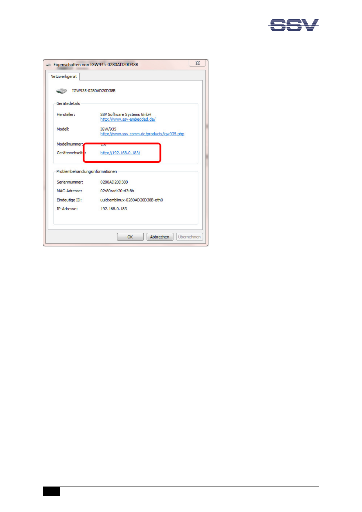
4.2 Accessing the SSV/WebUI with DHCP en bled
If the automatic IP address configuration of LAN1 via DHCP is enabled, you have to check the as-
signed IP address, which is necessary to access the IGW/935 via a Telnet client or a web browser
Therefore open in Windows Control Panel > Network and Internet > View network computers and
devices The IGW/935 should show up in this list
Fi ure 6: Selectin the IGW/935
Just ri ht-click on the IGW/935 to open the properties dialog, where you can see the current IP ad-
dress of the IGW/935 like shown in fi ure 7
A double-click on the IGW/935 opens the SSV/WebUI in a web browser
Please note:
To access the SSV/WebUI, it is important to add the port number 7777 to the
current IP address of the IGW/935, e g : http://192.168.0.126:7777!
Operation
10
IGW/935 //
First Steps
Fi ure 7: The properties dialo shows the current IP address
Now you are able to access the IGW/935 via a Telnet client or a web browser
Operation
IGW/935 // First Steps
11
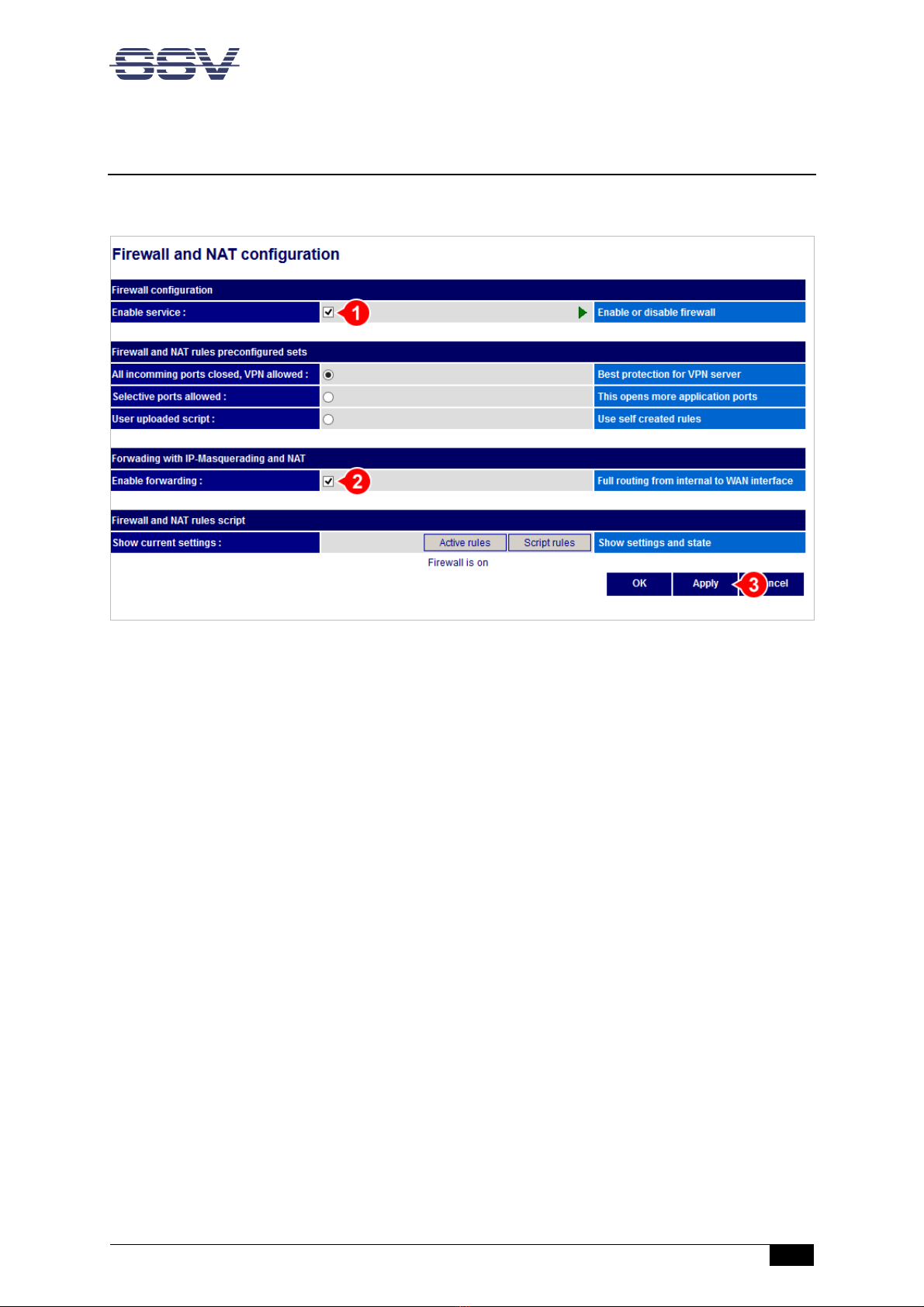
4.3 Firew ll Configur tion
Choose from the menu Services > Firewall and NAT
Fi ure 8: Firewall and NAT settin s
1. In the section Firewall confi uration enable the checkbox
2. In the section Forwarding with IP-Masquerading and NAT enable the checkbox
3. Click [Apply]
Operation
12
IGW/935 //
First Steps
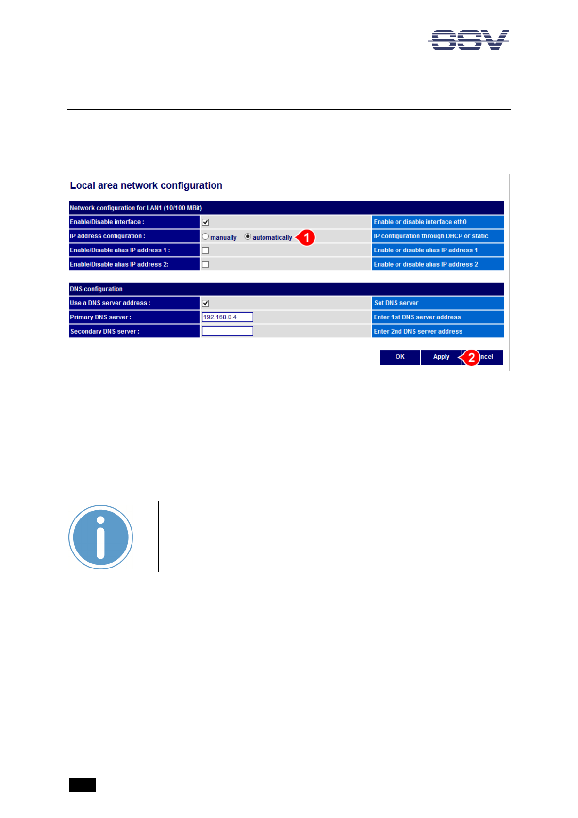
4.4 LAN Configur tion
The IP address of the LAN1 interface is ex-factory set to 192.168.0.126
To configure the LAN1 settings choose from the menu Network > LAN1
Fi ure 9: LAN1 settin s
To enable the automatic IP address assignment via DHCP follow these steps:
1. In the section IP address confi uration enable the radio button automatically
2. Click [Apply]
Please no
te:
After DHCP was enabled, it is necessary to re-log into the SSV/WebUI with the
new assigned IP address of LAN1 Please refer to chapter 4.2 to find out the cur-
rent IP address
Operation
IGW/935 // First Steps
13
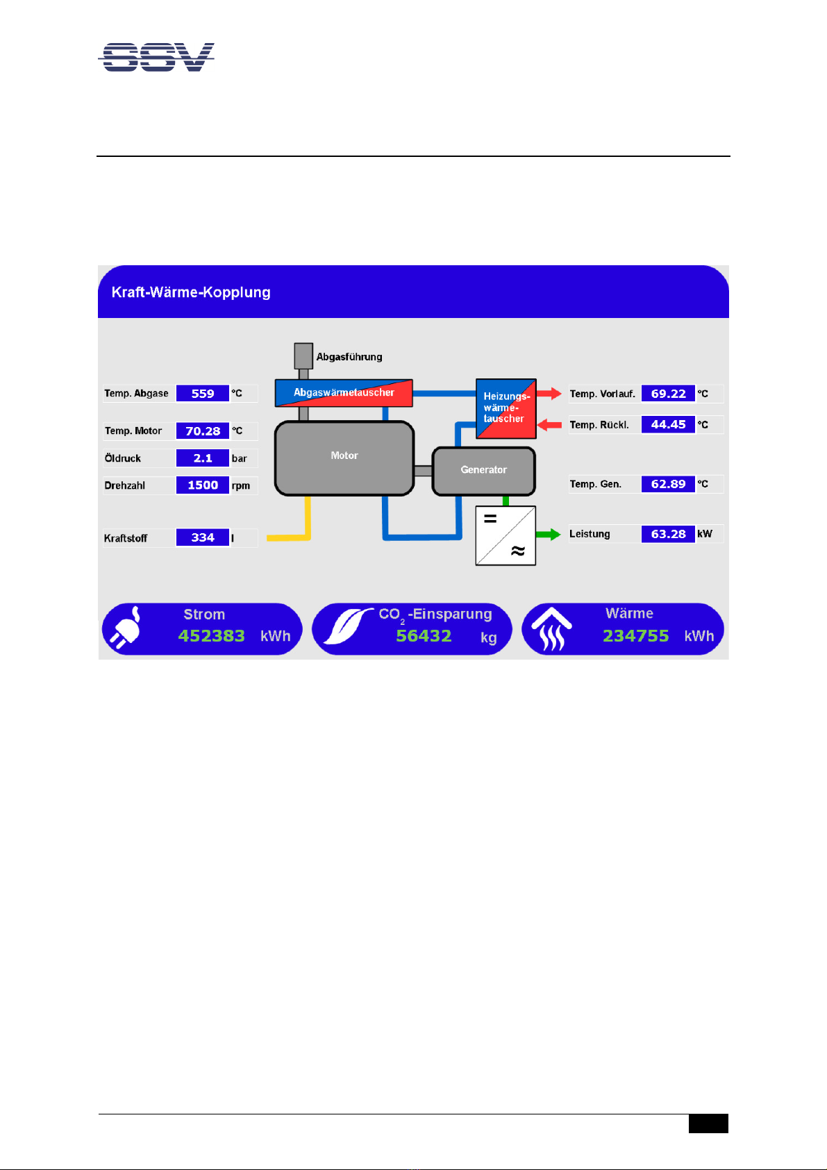
4.5 Accessing the SSV/WebUI Demo P ge
To open the demo page of the SSV/WebUI enter the current IP address of the IGW/935 in a web
browser:
192.168.0.126
Fi ure 10: Demo pa e of the SSV/WebUI

Operation
14
IGW/935 //
First Steps
4.6 Access vi Telnet
To access the IGW/935 via Telnet please open a Telnet client program (like e g TeraTerm) on your
host PC and enter the current IP address of the IGW/935 to activate a Telnet session
In the upcoming Telnet window you can login with the username root and the password root
Now you can enter any Linux commands, which will be executed by the IGW/935 operating system
Fi ure 11: Access via Telnet client
Please
note:
The ex-factory IP address of the LAN1 interface is 192.168.0.126 If DHCP is
enabled, please refer to chapter 4.2 to find out the current IP address
Operation
IGW/935 // First Steps
15
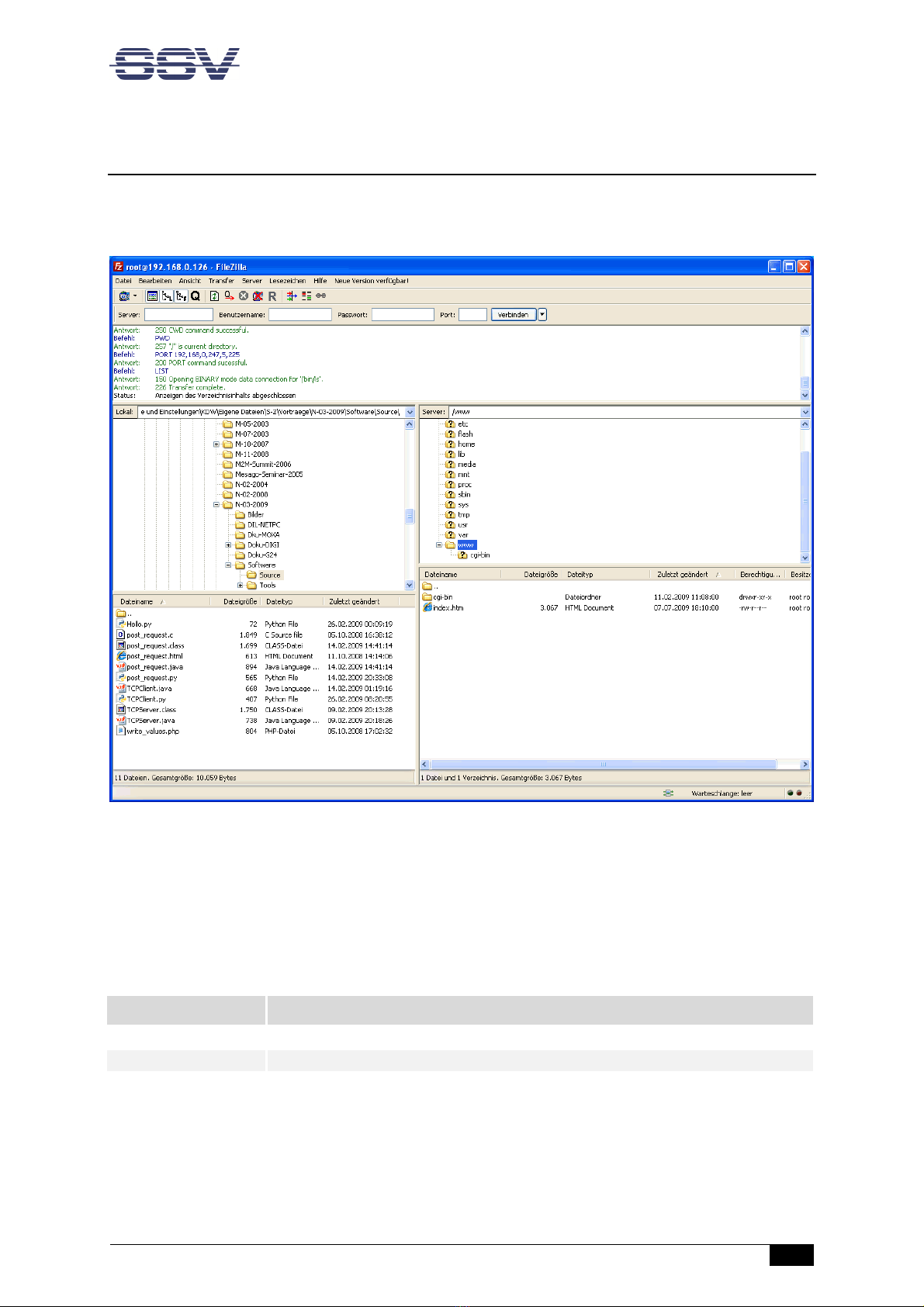
4.7 Access vi FTP
The IGW/935 comes with a pre-installed FTP server, which allows the file transfer via Ethernet be-
tween a PC and the IGW/935 To access the IGW/935 via FTP use an FTP client like e g FileZilla
Fi ure 12: FileZilla as FTP client to access the FTP server
Use for the FTP login the current IP address of the IGW/935, the username root and the password
root With this login you have FTP read/write permission in the file system
The default setting of the root file system after the boot process is read-only There are only three
exceptions, which are shown in the table 4:
D
irectory
Remark
/flash
R/W directory, non
-
volatile memory within Flash
/home/root
R/W directory, RAM disk, volatile memory
/var/volatile
R/W directory, RAM disk, volatile memory
Table 4: R/W directories in the file system
The read-only restriction protects all files of the file system Under ordinary operating conditions it is
not possible to overwrite or delete a file which is necessary for the eSOM/3517 within the IGW/935
Operation
16
IGW/935 //
First Steps
To disable the write protection just login with the username root and the password root and enter
the following command:
mount / -o remount,rw
This command „mounts„ the file system as read/write All files are now writable and deletable
Please pay attention not to damage important system files! With the command
mount / -o remount,ro
the system is set back to the read-only initial condition after the boot process
Please
note:
The ex-factory IP address of the LAN1 interface is 192.168.0.126 If DHCP is
enabled, please refer to chapter 4.2 to find out the current IP address
SOFTWARE EX ANSIONS & A S
IGW/935 // First Steps
17
5 SOFTWARE EXPANSIONS & APPS
SSV offers some apps for the IGW/935 to expand its functionality Most of the apps are for free;
some apps require a license The apps can be obtained on the following website:
https://www.ssv-embe e . e/ ownloa s/igw935/
6 TROUBLE SHOOTING IP ADDRESS PROBLEMS
If the IP address of LAN1 is not configured properly it is possible, that the SSV/WebUI (the configura-
tion user interface) of the IGW/935 cannot be accessed anymore
In that case it is necessary to restore the factory settings of the IGW/935 To do so, please follow
these steps:
1. Connect the LAN1 interface of the IGW/935 via a cross-over-cable with the LAN interface of a
Windows PC Disconnect (if present) the cable from the LAN2 interface of the IGW/935 If not
already running turn on the IGW/935
2. Make sure that DHCP (IP address is obtained automatically) is enabled within the network
settings of the Windows PC for the LAN interface
3. Take a USB memory stick and format it under Windows with FAT16 or FAT32
4. Create a new simple text file on the memory stick, name it factoryreset and remove the
file extension
Please note:
Keep in mind that Windows hides file extensions by default!
5. At first unmount the memory stick over the USB symbol in the Windows system tray before
removing it from the PC
6. Now plug the memory stick into the USB port of the (running) IGW/935
7. The IGW/935 makes a reboot and the LED S1 turns off after 15 to 30 seconds
8. Remove the memory stick (at the latest when the LED S1 begins to blink)
9. The Windows PC shows the message Network restricted after 30 to 60 seconds
10. The IGW/935 answers via UPnP with its new IP address within the AutoIP range of
169.254.x.x It can now be found as an icon within the Windows network environment
A double click on this icon opens the IGW/935’s login page in a browser The URL of the login
page looks like this: http://169.256.x.x:7777

Technical Information
18
IGW/935 //
First Steps
7 TECHNICAL INFORMATION
7.1 Technic l D t
Supply voltage 12 24 VDC ±10%
Weight < 0,5 kg
Mechanical Dimensions (LxWxH) 112 mm x 22 5 mm x 100 mm
Temperature range 0° C – 60° C
Rel air himudity max 85%
7.2 Pinout Screw Termin ls
Terminal
Signal
A1
COM2 Serial Port: RS485 RX/TX+
A2
COM2 Serial Port: RS485 RX/TX
-
A3
Vin
+
(1
2
2
4
VDC)
A4
Vin
-
Table 5: Pinout screw terminals
Please note:
The RS485 (officially called TIA/EIA-485-A) connection between your IGW/935
and the field devices needs termination resistors on both ends for proper oper-
ation The IGW/935 does not offer internal termination resistors Please make
sure, that the RS485 cable connection is equipped with external termination re-
sistors.

Helpful Literature
IGW/935 // First Steps
19
8 HELPFUL LITERATURE
IGW/935 Hardware Reference
eSOM/3517 Hardware Reference
CONTACT
SSV SOFTWARE SYSTEMS GmbH
Dünenweg 5
30419 Hannover
Phone: +49 (0)511/40 000-0
Fax: +49 (0)511/40 000-40
E-mail: [email protected]
Web: www.ssv-embedded.de
Forum: www.ssv-comm.de/forum
Social: www.linkedin.com/company/ssv-software-systems
DOCUMENT HISTORY
Revision
Date
Remarks
Name
Review
1.0
2012
-
12
-
20
First version
WBU
HNE
1.1
2013
-
03
-
08
Added chapter 4.3
WBU
HNE
1.2
2018
-
06
-
2
Edited chapter 4
WBU
HNE
1.3
2018
-
08
-
2
Added chapter
WBU
HNE
1.4
2023
-
07
-
11
New layout, removed information about DVI
WBU
ENE
The contents of this document are subject to change without prior notice. SSV does not assume any liability and does not
gua
rantee that the presented information is accurate or complete. The information in this document is provided 'as is' with-
out warranty of any kind. Some names within this document may be trademarks of their respective holders.
© 2023 SSV SOFTWARE SYSTEMS GMBH. All rights reserved.
Other manuals for IGW/935
2
Table of contents
Other SSV Gateway manuals

SSV
SSV RMG/938 User manual

SSV
SSV MGW/865 User manual

SSV
SSV RMG/941L User manual

SSV
SSV IGW/935 Application guide

SSV
SSV RMG/941 Series Application guide

SSV
SSV IGW/925-W Application guide

SSV
SSV IGW/920 User manual

SSV
SSV IGW/922 Application guide

SSV
SSV IGW/925 Installation and user guide

SSV
SSV IGW/935 User manual


Popular Gateway manuals by other brands

Packet Force
Packet Force RVSG-4014 user manual

Network Electronics
Network Electronics SDI-IP-GTW user manual

Patton
Patton SmartNode 10200 Series quick start guide

The Things Network
The Things Network TTN Gateway v1 - EU Assembly instructions

Daikin
Daikin intelligent Touch Manager BACnet DCM014A51 Design guide

Dell
Dell PowerConnect J-SRX100 Hardware guide


