ST 32F412GDISCOVERY User manual

October 2021 UM2032 Rev 3 1/40
1
UM2032
User manual
Discovery kit with STM32F412ZG MCU
Introduction
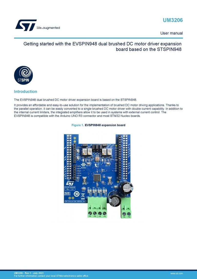
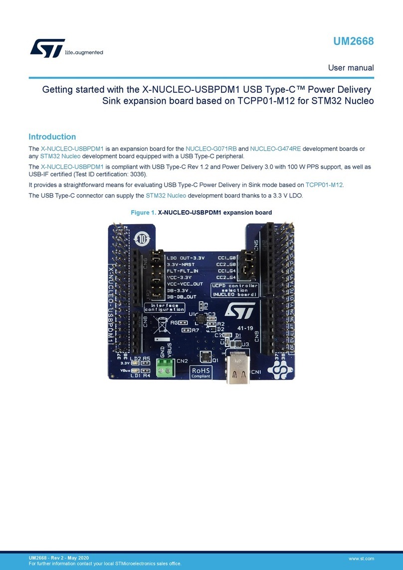
The 32F412GDISCOVERY Discovery kit is a complete demonstration and development
platform for STMicroelectronics Arm®Cortex®-M4 core-based STM32F412ZGT6
microcontroller. This microcontroller features four I2C buses, four USART ports, five SPI
ports with two multiplexed full-duplex I2S buses, SDIO interface, USB OTG full-speed 2.0
port, two CAN buses, FMC parallel interface, two digital filters for sigma-delta modulators,
PDM interface for two digital microphones, one 12-bit ADC, dual Quad-SPI interface, JTAG
and SWD debugging support. This Discovery kit offers everything required for users to get
started quickly and develop applications easily.
A full range of hardware features on the board helps users to evaluate on-board peripherals
such as: USB OTG FS, microSD™ card, full-duplex I2S with an audio codec and stereo jack
for headset including analog microphone, DFSDM with a pair of ST-MEMS digital
microphones on board, Quad-SPI Flash memory device, 1.54" TFT LCD using FMC
interface with capacitive touch panel.
The ARDUINO®Uno V3 compatible connectors expand the functionality with a wide choice
of specialized shields. The extension connectors allow easy connection of a daughterboard
for specific customer applications. The integrated ST-LINK/V2-1 provides an embedded
in-circuit debugger and programmer for the STM32.
Pictures are not contractual.
Figure 1. 32F412GDISCOVERY (top view) Figure 2. 32F412GDISCOVERY (bottom view)
www.st.com

Contents UM2032
2/40 UM2032 Rev 3
Contents
1 Features . . . . . . . . . . . . . . . . . . . . . . . . . . . . . . . . . . . . . . . . . . . . . . . . . . . 7
2 Ordering information . . . . . . . . . . . . . . . . . . . . . . . . . . . . . . . . . . . . . . . . 8
2.1 Codification . . . . . . . . . . . . . . . . . . . . . . . . . . . . . . . . . . . . . . . . . . . . . . . . . 8
3 Development environment . . . . . . . . . . . . . . . . . . . . . . . . . . . . . . . . . . . . 9
3.1 System requirements . . . . . . . . . . . . . . . . . . . . . . . . . . . . . . . . . . . . . . . . . 9
3.2 Development toolchains . . . . . . . . . . . . . . . . . . . . . . . . . . . . . . . . . . . . . . . 9
4 Conventions . . . . . . . . . . . . . . . . . . . . . . . . . . . . . . . . . . . . . . . . . . . . . . . . 9
5 Hardware layout and configuration . . . . . . . . . . . . . . . . . . . . . . . . . . . . 10
5.1 32F412GDISCOVERY Discovery kit mechanical drawing . . . . . . . . . . . . 13
5.2 Embedded ST-LINK/V2-1 . . . . . . . . . . . . . . . . . . . . . . . . . . . . . . . . . . . . . 13
5.2.1 Drivers . . . . . . . . . . . . . . . . . . . . . . . . . . . . . . . . . . . . . . . . . . . . . . . . . . 13
5.2.2 ST-LINK/V2-1 firmware upgrade . . . . . . . . . . . . . . . . . . . . . . . . . . . . . . 14
5.3 Power supply . . . . . . . . . . . . . . . . . . . . . . . . . . . . . . . . . . . . . . . . . . . . . . 14
5.3.1 Power supply sources . . . . . . . . . . . . . . . . . . . . . . . . . . . . . . . . . . . . . . 14
5.3.2 STM32 power supply options . . . . . . . . . . . . . . . . . . . . . . . . . . . . . . . . 15
5.3.3 Modification of STM32 voltage . . . . . . . . . . . . . . . . . . . . . . . . . . . . . . . 15
5.3.4 Supplying the 32F412GDISCOVERY through
the ST-LINK/V2-1 USB port . . . . . . . . . . . . . . . . . . . . . . . . . . . . . . . . . . 16
5.3.5 Programming/debugging when the power supply
is not from ST-LINK/V2-1 . . . . . . . . . . . . . . . . . . . . . . . . . . . . . . . . . . . . 17
5.3.6 Measurement of current IDD drawn by the microcontroller . . . . . . . . . . 17
5.4 Clock source . . . . . . . . . . . . . . . . . . . . . . . . . . . . . . . . . . . . . . . . . . . . . . . 20
5.4.1 HSE clock source . . . . . . . . . . . . . . . . . . . . . . . . . . . . . . . . . . . . . . . . . 20
5.4.2 LSE clock source . . . . . . . . . . . . . . . . . . . . . . . . . . . . . . . . . . . . . . . . . . 20
5.5 Reserved use of solder bridges . . . . . . . . . . . . . . . . . . . . . . . . . . . . . . . . 20
5.6 Reset source . . . . . . . . . . . . . . . . . . . . . . . . . . . . . . . . . . . . . . . . . . . . . . 20
5.7 Boot options . . . . . . . . . . . . . . . . . . . . . . . . . . . . . . . . . . . . . . . . . . . . . . . 21
5.8 Audio codec . . . . . . . . . . . . . . . . . . . . . . . . . . . . . . . . . . . . . . . . . . . . . . . 22
5.8.1 Stereo headset and headphone jack . . . . . . . . . . . . . . . . . . . . . . . . . . . 22
5.8.2 Loudspeaker output . . . . . . . . . . . . . . . . . . . . . . . . . . . . . . . . . . . . . . . . 22

UM2032 Rev 3 3/40
UM2032 Contents
4
5.9 Digital microphones . . . . . . . . . . . . . . . . . . . . . . . . . . . . . . . . . . . . . . . . . 22
5.10 USB OTG FS . . . . . . . . . . . . . . . . . . . . . . . . . . . . . . . . . . . . . . . . . . . . . . 22
5.10.1 32F412GDISCOVERY is USB device . . . . . . . . . . . . . . . . . . . . . . . . . . 23
5.10.2 32F412GDISCOVERY is USB host . . . . . . . . . . . . . . . . . . . . . . . . . . . . 23
5.11 microSD™ card . . . . . . . . . . . . . . . . . . . . . . . . . . . . . . . . . . . . . . . . . . . . 23
5.12 I2C extension connector . . . . . . . . . . . . . . . . . . . . . . . . . . . . . . . . . . . . . . 23
5.13 Quad-SPI NOR Flash memory . . . . . . . . . . . . . . . . . . . . . . . . . . . . . . . . . 24
5.14 Virtual COM port . . . . . . . . . . . . . . . . . . . . . . . . . . . . . . . . . . . . . . . . . . . . 24
5.15 ARDUINO®Uno V3 connectors . . . . . . . . . . . . . . . . . . . . . . . . . . . . . . . . 24
5.16 Extension connectors P1 and P2 . . . . . . . . . . . . . . . . . . . . . . . . . . . . . . . 26
5.17 LCD display, backlight and touch panel . . . . . . . . . . . . . . . . . . . . . . . . . . 28
5.17.1 LCD display . . . . . . . . . . . . . . . . . . . . . . . . . . . . . . . . . . . . . . . . . . . . . . 28
5.17.2 LCD signal access (CN7) . . . . . . . . . . . . . . . . . . . . . . . . . . . . . . . . . . . 29
5.17.3 Backlight . . . . . . . . . . . . . . . . . . . . . . . . . . . . . . . . . . . . . . . . . . . . . . . . 30
5.17.4 Touch panel . . . . . . . . . . . . . . . . . . . . . . . . . . . . . . . . . . . . . . . . . . . . . . 30
5.18 Joystick and LEDs . . . . . . . . . . . . . . . . . . . . . . . . . . . . . . . . . . . . . . . . . . 30
6 Connectors . . . . . . . . . . . . . . . . . . . . . . . . . . . . . . . . . . . . . . . . . . . . . . . 32
6.1 I2C extension connector CN10 . . . . . . . . . . . . . . . . . . . . . . . . . . . . . . . . . 32
6.2 USB OTG FS Micro-AB connector CN3 . . . . . . . . . . . . . . . . . . . . . . . . . . 32
6.3 microSD™ connector CN13 . . . . . . . . . . . . . . . . . . . . . . . . . . . . . . . . . . . 33
6.4 ST-LINK/V2-1 USB Micro-B connector CN6 . . . . . . . . . . . . . . . . . . . . . . 33
7 32F412GDISCOVERY Discovery kit information . . . . . . . . . . . . . . . . . 35
7.1 Product marking . . . . . . . . . . . . . . . . . . . . . . . . . . . . . . . . . . . . . . . . . . . . 35
7.2 32F412GDISCOVERY product history . . . . . . . . . . . . . . . . . . . . . . . . . . . 36
7.2.1 Product identification 32F412GDISCO/ . . . . . . . . . . . . . . . . . . . . . . . . . 36
7.2.2 Product identification DK32F412G$AU1 . . . . . . . . . . . . . . . . . . . . . . . . 36
7.3 Board revision history . . . . . . . . . . . . . . . . . . . . . . . . . . . . . . . . . . . . . . . . 36
7.3.1 MB1209 revision D-02 . . . . . . . . . . . . . . . . . . . . . . . . . . . . . . . . . . . . . . 36
7.3.2 MB1209 revision D-04 . . . . . . . . . . . . . . . . . . . . . . . . . . . . . . . . . . . . . . 36
7.4 Board known limitations . . . . . . . . . . . . . . . . . . . . . . . . . . . . . . . . . . . . . . 36
7.4.1 MB1209 revision D-02 . . . . . . . . . . . . . . . . . . . . . . . . . . . . . . . . . . . . . . 36
7.4.2 MB1209 revision D-04 . . . . . . . . . . . . . . . . . . . . . . . . . . . . . . . . . . . . . . 36

Contents UM2032
4/40 UM2032 Rev 3
8 Federal Communications Commission (FCC)
and ISED Canada Compliance Statements . . . . . . . . . . . . . . . . . . . . . . 37
8.1 FCC Compliance Statement . . . . . . . . . . . . . . . . . . . . . . . . . . . . . . . . . . . 37
8.1.1 Part 15.19 . . . . . . . . . . . . . . . . . . . . . . . . . . . . . . . . . . . . . . . . . . . . . . . 37
8.1.2 Part 15.21 . . . . . . . . . . . . . . . . . . . . . . . . . . . . . . . . . . . . . . . . . . . . . . . 37
8.1.3 Part 15.105 . . . . . . . . . . . . . . . . . . . . . . . . . . . . . . . . . . . . . . . . . . . . . . 37
8.2 ISED Compliance Statement . . . . . . . . . . . . . . . . . . . . . . . . . . . . . . . . . . 37
9 CE conformity . . . . . . . . . . . . . . . . . . . . . . . . . . . . . . . . . . . . . . . . . . . . . 38
Revision history . . . . . . . . . . . . . . . . . . . . . . . . . . . . . . . . . . . . . . . . . . . . . . . . . . . . 39

UM2032 Rev 3 5/40
UM2032 List of tables
5
List of tables
Table 1. Ordering information . . . . . . . . . . . . . . . . . . . . . . . . . . . . . . . . . . . . . . . . . . . . . . . . . . . . . . . 8
Table 2. Codification explanation . . . . . . . . . . . . . . . . . . . . . . . . . . . . . . . . . . . . . . . . . . . . . . . . . . . . 8
Table 3. ON/OFF conventions . . . . . . . . . . . . . . . . . . . . . . . . . . . . . . . . . . . . . . . . . . . . . . . . . . . . . . 9
Table 4. Power-supply-related jumper settings . . . . . . . . . . . . . . . . . . . . . . . . . . . . . . . . . . . . . . . . 17
Table 5. Boot options . . . . . . . . . . . . . . . . . . . . . . . . . . . . . . . . . . . . . . . . . . . . . . . . . . . . . . . . . . . . 21
Table 6. Boot-related solder bridge and resistor settings . . . . . . . . . . . . . . . . . . . . . . . . . . . . . . . . . 21
Table 7. ARDUINO®Uno V3 compatible connectors . . . . . . . . . . . . . . . . . . . . . . . . . . . . . . . . . . . . 24
Table 8. Pin assignment for the extension connector P1 . . . . . . . . . . . . . . . . . . . . . . . . . . . . . . . . . 26
Table 9. Pin assignment for the extension connector P2 . . . . . . . . . . . . . . . . . . . . . . . . . . . . . . . . . 27
Table 10. Pin assignment for connector CN15 . . . . . . . . . . . . . . . . . . . . . . . . . . . . . . . . . . . . . . . . . . 28
Table 11. Pin assignment for connector CN7 . . . . . . . . . . . . . . . . . . . . . . . . . . . . . . . . . . . . . . . . . . 29
Table 12. Port assignment to the LED indicators . . . . . . . . . . . . . . . . . . . . . . . . . . . . . . . . . . . . . . . . 31
Table 13. I2C extension connector pinout CN10 . . . . . . . . . . . . . . . . . . . . . . . . . . . . . . . . . . . . . . . . 32
Table 14. USB OTG FS Micro-AB connector CN3 . . . . . . . . . . . . . . . . . . . . . . . . . . . . . . . . . . . . . . . 32
Table 15. microSD™ connector CN13 . . . . . . . . . . . . . . . . . . . . . . . . . . . . . . . . . . . . . . . . . . . . . . . . 33
Table 16. USB Micro-B connector CN6 . . . . . . . . . . . . . . . . . . . . . . . . . . . . . . . . . . . . . . . . . . . . . . . 34
Table 17. Document revision history . . . . . . . . . . . . . . . . . . . . . . . . . . . . . . . . . . . . . . . . . . . . . . . . . 39

List of figures UM2032
6/40 UM2032 Rev 3
List of figures
Figure 1. 32F412GDISCOVERY (top view) . . . . . . . . . . . . . . . . . . . . . . . . . . . . . . . . . . . . . . . . . . . . . 1
Figure 2. 32F412GDISCOVERY (bottom view) . . . . . . . . . . . . . . . . . . . . . . . . . . . . . . . . . . . . . . . . . . 1
Figure 3. Hardware block diagram. . . . . . . . . . . . . . . . . . . . . . . . . . . . . . . . . . . . . . . . . . . . . . . . . . . 10
Figure 4. 32F412GDISCOVERY top layout . . . . . . . . . . . . . . . . . . . . . . . . . . . . . . . . . . . . . . . . . . . . 11
Figure 5. 32F412GDISCOVERY bottom layout . . . . . . . . . . . . . . . . . . . . . . . . . . . . . . . . . . . . . . . . . 12
Figure 6. 32F412GDISCOVERY mechanical drawing (dimensions in millimeters) . . . . . . . . . . . . . . 13
Figure 7. Updating the list of drivers in device manager . . . . . . . . . . . . . . . . . . . . . . . . . . . . . . . . . . 14
Figure 8. R90 and R92 resistors . . . . . . . . . . . . . . . . . . . . . . . . . . . . . . . . . . . . . . . . . . . . . . . . . . . . 15
Figure 9. I2C extension connector CN10 (front view) . . . . . . . . . . . . . . . . . . . . . . . . . . . . . . . . . . . . 32
Figure 10. USB OTG FS Micro-AB connector CN3 (front view). . . . . . . . . . . . . . . . . . . . . . . . . . . . . . 32
Figure 11. microSD™ connector CN13 (front view). . . . . . . . . . . . . . . . . . . . . . . . . . . . . . . . . . . . . . . 33
Figure 12. USB Micro-B connector CN6 (front view) . . . . . . . . . . . . . . . . . . . . . . . . . . . . . . . . . . . . . . 33

UM2032 Rev 3 7/40
UM2032 Features
39
1 Features
•STM32F412ZGT6 microcontroller, based on the Arm®(a) Cortex®-M4 processor,
featuring 1 Mbyte of Flash memory and 256 Kbytes of RAM in an LQFP144 package
•1.54-inch, 240x240 pixel TFT color LCD with parallel interface and capacitive touch
panel
•USB OTG FS
•I2S audio codec
•Stereo digital ST-MEMS microphones
•128-Mbit Quad-SPI NOR Flash memory
•Reset push-button and joystick
•4 color user LEDs
•Board connectors
– microSD™ card
– User USB with Micro-AB
– Stereo headset jack with analog microphone input and a loudspeaker output
–I
2C expansion connector
– ARDUINO®Uno V3 expansion connectors
– 2.54 mm pitch expansion connector for direct access to various features of the
STM32F412ZGT6 microcontroller
•Flexible power-supply options:
–ST-LINK/V2-1
– User USB FS connector
– VIN from ARDUINO®Uno V3
– +5 V from ARDUINO®Uno V3
•2.0 V and 3.3 V supply voltage options for the STM32F412ZGT6
•Comprehensive free software libraries and examples available with the STM32Cube
MCU Package
•On-board ST-LINK/V2-1 debugger/programmer with USB re-enumeration capability:
mass storage, Virtual COM port, and debug port
•Support of a wide choice of Integrated Development Environments (IDEs) including
IAR Embedded Workbench®, MDK-ARM, and STM32CubeIDE
a. Arm is a registered trademark of Arm Limited (or its subsidiaries) in the US and/or elsewhere.

Ordering information UM2032
8/40 UM2032 Rev 3
2 Ordering information
To order the 32F412GDISCOVERY Discovery kit, refer to Tabl e 1. Additional information is
available from the datasheet and reference manual of the target microcontroller.
2.1 Codification
The meaning of the codification is explained in Table 2.
Table 1. Ordering information
Order code Board reference Target STM32
STM32F412G-DISCO MB1209 STM32F412ZGT6
Table 2. Codification explanation
STM32F4XXY-DISCO Description Example: STM32F412G-DISCO
STM32F4 MCU series in STM32 32-bit Arm Cortex
MCUs STM32F4 Series
XX MCU product line in the series STM32F412
YSTM32 Flash memory size:
– G for 1 Mbyte 1 Mbyte
DISCO Discovery kit Discovery kit

UM2032 Rev 3 9/40
UM2032 Development environment
39
3 Development environment
3.1 System requirements
•Multi.OS support: Windows®10, Linux® (a) 64-bit, or macOS® (b)
•USB Type-A or USB Type-C®to Micro-B cable
3.2 Development toolchains
•IAR Systems®- IAR Embedded Workbench® (c)
•Keil®- MDK-ARM(c) (d)
•STMicroelectronics - STM32CubeIDE
4 Conventions
Table 3 provides the definition of some conventions used in the present document.
a. Linux®is a registered trademark of Linus Torvalds.
b. macOS®is a trademark of Apple Inc. registered in the U.S. and other countries.
c. On Windows®only.
d. All other trademarks are the property of their respective owners.
Table 3. ON/OFF conventions
Convention Definition
Jumper JPx ON Jumper fitted
Jumper JPx OFF Jumper not fitted
Solder bridge SBx ON SBx connections closed by solder
Solder bridge SBx OFF SBx connections left open

Hardware layout and configuration UM2032
10/40 UM2032 Rev 3
5 Hardware layout and configuration
The 32F412GDISCOVERY Discovery kit is designed around the STM32F412ZGT6 (144-pin
TQFP package). The hardware block diagram shown in Figure 3, illustrates the
STM32F412ZGT6 connections with the peripherals. Figure 4 and Figure 5 show the
location of the main components on the Discovery kit.
Figure 3. Hardware block diagram
MSv41795V1
STM32F412ZGT6
TQFP144 package
Audio CODEC
RTC
3.3 V power
supply
I2C1
I2S3
I2C extension
connector
1.54" LCD
Joystick
GPIO
SDIO
QSPI
OTG
FS USB connector
USART2
FSMC
GPIOs
SWD
Stereo headset output
Stereo digital
microphones
DFSDM
LCD touch
panel
ARDUINO®
connectors
Extension
connectors
I2C2
2.0 V power
supply
Monophonic loudspeaker output
Analog microphone input
GPIOs
GPIOs
128-Mbyte
Quad-SPI
Flash memory
4x LEDs
ST-LINK/V2-1
microSD™ card
connector
32 KHz crystal

UM2032 Rev 3 11/40
UM2032 Hardware layout and configuration
39
Figure 4. 32F412GDISCOVERY top layout
MSv41786V2
I2C extension connector
(CN10)
ARDUINO®LED
(LD9)
Reset button (B1)
VBUS LED (LD7)
USB fault LED (LD8)
User LEDs
(LD1, LD2, LD3, LD4)
Joystick (B2)
Extension connector (P1)
LCD (ZZ1)
ARDUINO®connectors
(CN1, CN2)
Supply source selection
(JP3)
+5 V power LED (LD6)
SWD connector (CN4)
ST-LINK/V2-1 Micro-B USB connector (CN6)
ST-LINK power switch fault LED
(LD10)
ARDUINO®connectors
(CN11, CN12)
STM32F412ZGT6 (U7)
Extension connector (P2)
microSD™ connector
(CN13)
Audio jack (CN9) Digital microphones (U4, U5)
USB OTG FS
Micro-AB connector (CN3)
IDD jumper (JP7)
VDD_USB source selection
(JP6)
VDD_MCU voltage selection
(JP5)

Hardware layout and configuration UM2032
12/40 UM2032 Rev 3
Figure 5. 32F412GDISCOVERY bottom layout
MSv43307V2
Capacitive touch panel
connector (CN14)
microSD™ connector
(CN13)
U16 regulator output
voltage adjustment
(R90, R92)

UM2032 Rev 3 13/40
UM2032 Hardware layout and configuration
39
5.1 32F412GDISCOVERY Discovery kit mechanical drawing
Figure 6. 32F412GDISCOVERY mechanical drawing (dimensions in millimeters)
5.2 Embedded ST-LINK/V2-1
ST-LINK/V2-1 programming and debugging tool is integrated into the
32F412GDISCOVERY Discovery kit.
For information about the debugging and programming features, refer to the ST-LINK/V2 in-
circuit debugger/programmer for STM8 and STM32 user manual (UM1075). For a
comparison of the various ST-LINK solutions, refer to the Overview of ST-LINK derivatives
technical note (TN1235).
5.2.1 Drivers
ST-LINK/V2-1 requires a dedicated USB driver, which, for Windows®7, Windows®8 and
Windows®10, is available from www.st.com.
In cases where the STM32F412 Discovery board is connected to the PC before the driver is
installed, some STM32F412 Discovery board interfaces might be declared as “Unknown” in
the PC device manager. In such cases, the user must install the dedicated driver files and
update the driver of the connected device from the device manager, as shown in Figure 7.
Note: It is preferable to use the “USB Composite Device” handle for a full recovery.
28
1
6
5
4
85
4
13
12
48
1
8
24
37
11
2
5
6
10
7
25
36
25
2
1
1
109
108
73
6
2
1
72
144
37
1 8
8 1
8
5
36
4
5
31
D
A
50
49
50
49
29
28
22
2
23
44
226
1
50.8
172
5.08
22.86
65.68
59.35
4.06
23.79
67 48.26

Hardware layout and configuration UM2032
14/40 UM2032 Rev 3
Figure 7. Updating the list of drivers in device manager
5.2.2 ST-LINK/V2-1 firmware upgrade
ST-LINK/V2-1 embeds a mechanism for in-situ firmware upgrade through the USB port. As
firmware may evolve during the lifespan of the ST-LINK/V2-1 product (for example new
functionalities, bug fixes, support for new microcontroller families), visiting the www.st.com
website is recommended before starting to use the STM32F412 Discovery board, then
periodically to stay up-to-date with the latest firmware version.
5.3 Power supply
5.3.1 Power supply sources
The 32F412GDISCOVERY Discovery kit is designed to be powered by the following
sources:
•5 V DC from the ST-LINK/V2-1 USB connector CN6 with 500 mA current limitation.
Power mechanism of supplying the Discovery kit by the ST-LINK/V2-1 is explained in
Section 5.3.4: Supplying the 32F412GDISCOVERY through the ST-LINK/V2-1 USB
port. A jumper should be placed in location STLK of JP3, connecting pins 3 and 4. The
green LED LD6 is lighted on to confirm the presence of +5 V voltage.
•5 V DC from the user USB FS connector CN3. A jumper should be placed in location
USB of JP3, connecting pins 5 and 6. The green LED LD6 is lighted on to confirm the
presence of +5 V voltage.
•6 V to 9 V DC from VIN pin of ARDUINO®Uno V3 compatible connector CN2. The
voltage is limited to 9 V to keep the temperature of the regulator U3 within his thermal
safe area. A jumper should be placed in location E5V of jumper JP3, connecting pin 1
to pin 2 of JP3. The green LED LD6 is lighted on to confirm the presence of +5 V
voltage.
•5 V DC from +5 V pin of ARDUINO®Uno V3 connector (CN2 pin 5) with limitations.
The jumpers on JP3 and CN5 have to be removed, SB21 (NRST) and SB28 (SWO)
have to be OFF. In such configuration the ST-LINK/V2-1 MCU is not powered, as
consequence the 8 MHz of the ST-LINK/V2-1 cannot be used as external input clock
for the STM32.
For details on JP3 jumper setting refer to Table 4: Power-supply-related jumper settings.

UM2032 Rev 3 15/40
UM2032 Hardware layout and configuration
39
5.3.2 STM32 power supply options
The 32F412GDISCOVERY offers the possibility to supply the STM32 under 2.0 V or 3.3 V.
A jumper must be placed in location 2.0 V of JP5 to supply the STM32 under 2.0 V, then
pins 2 and 3 are connected. Similarly the jumper must be placed in 3.3 V to supply the
STM32 with 3.3 V, then pins 1 and 2 of JP5 are connected.
For details on JP5 jumper setting refer to Table 4: Power-supply-related jumper settings.
5.3.3 Modification of STM32 voltage
Regulator U16 is dedicated to the 2.0 V supply. The output voltage of U16 is by default 2.0 V
but it is adjustable depending on the resistors R90 and R92 which are by default 120 and
68 ohms respectively. The output voltage is calculated as follows:
VOUT VREF 1 R92()R90()÷+()×=
with VREF = 1.25 V.
If necessary, resistors R90 and R92 can be changed to modify the STM32 supply voltage.
R90 and R92 are easily located bottom side of the Discovery kit near U16 (see Figure 5 and
Figure 8).
Figure 8. R90 and R92 resistors

Hardware layout and configuration UM2032
16/40 UM2032 Rev 3
5.3.4 Supplying the 32F412GDISCOVERY through
the ST-LINK/V2-1 USB port
To power the 32F412GDISCOVERY through the ST-LINK/V2-1, the USB host (a PC) gets
connected with the 32F412GDISCOVERY Micro-B USB receptacle CN6, via a USB cable.
This event starts the USB enumeration procedure. In its initial phase, the current supply
capability of the USB port located on the host, is limited to 100 mA. It is enough because
only the ST-LINK/V2-1 part of the 32F412GDISCOVERY Discovery kit draws power at that
time. If the solder bridge SB18 is OFF (default configuration), the U8 ST890 power switch is
set to OFF position, and only the ST-LINK/V2-1 is powered. In the next phase of the
enumeration procedure, the host PC informs the ST-LINK/V2-1 facility of its capability to
supply up to 500 mA of current. If the answer is positive, the ST-LINK/V2-1 sets the U8
switch to ON position to supply power to the remainder of the 32F412GDISCOVERY
Discovery kit. If the PC USB port is not capable of supplying up to 500 mA of current,
another power source should be used like VIN pin of connector CN2.
Should a short-circuit occur on the Discovery kit, the power switch protects the USB port of
the host against current demand exceeding 600 mA. In such an event, the red LED FAULT
LD10 lights on.
The 32F412GDISCOVERY Discovery kit can also be supplied from a USB power source not
supporting enumeration, such as a USB charger. In this particular case, SB18 solder bridge
must be ON. ST-LINK/V2-1 turns the power switch ON regardless of the enumeration
procedure result and passes the power unconditionally to the Discovery kit.
The green LED LD6 turns on whenever the Discovery kit is powered.

UM2032 Rev 3 17/40
UM2032 Hardware layout and configuration
39
5.3.5 Programming/debugging when the power supply
is not from ST-LINK/V2-1
Before connecting the USB cable from the ST-LINK/V2-1 USB connector CN6 to the PC, it
is mandatory to power the Discovery kit using the user USB FS connector CN3 or the VIN
pin of the ARDUINO®Uno V3 connector CN2. Proceeding this way, ensures that the
enumeration succeeds thanks to the external power source.
The following power sequence procedure must be respected:
1. Put a jumper in JP3 at location USB to use power from the user USB CN3 or at location
E5V to use power from VIN of ARDUINO®Uno V3 connector CN2.
2. Connect the corresponding external power source.
3. Check that the green LED LD6 is turned ON
4. Connect the PC to the ST-LINK/V2-1 USB connector CN6
If this order is not respected, the Discovery kit may be powered by VBUS first from ST-
LINK/V2-1, and the following risks may be encountered:
1. If more than 500 mA current is needed by the Discovery kit, the PC may be damaged
or current can be limited by PC. As a consequence the Discovery kit is not powered
correctly.
2. 500 mA is requested at the enumeration. If the PC cannot provide such current there is
a risk that the request is rejected and the enumeration does not succeed.
5.3.6 Measurement of current IDD drawn by the microcontroller
The jumper JP7 should be ON by default to supply the STM32F412ZGT6. To measure the
current IDD drawn by the microcontroller STM32F412ZGT6 only, remove the jumper JP7
and replace it by a multimeter (see Table 4).
Table 4. Power-supply-related jumper settings
Jumper Description
JP3
Default Setting
32F412GDISCOVERY is supplied through the Micro-B ST-LINK/V2-1 connector
CN6. Jumper in STLK place.
32F412GDISCOVERY is supplied through CN3 Micro-AB USB FS connector.
Jumper in USB place.
USB
STLK
E5V
1
USB
STLK
E5V
1

Hardware layout and configuration UM2032
18/40 UM2032 Rev 3
JP3
32F412GDISCOVERY is supplied through the VIN pin of the ARDUINO®Uno V3
compatible connector CN2. Jumper in E5V place.
32F412GDISCOVERY is supplied by +5 V pin of ARDUINO®Uno V3 compatible
connector CN2 (pin 5) or by pins 3 or 4 of the extension connector P2. No jumper in
JP3.
JP5
Default Setting
STM32F412ZGT6 is supplied with a +3.3 V voltage (VDD_MCU).
STM32F412ZGT6 STM32 is supplied with a +2.0 V voltage (VDD_MCU).
JP6
Default Setting
VDD_USB power pin of STM32F412ZGT6 is supplied with same voltage VDD_MCU
as remainder supply pins of STM32.
Table 4. Power-supply-related jumper settings (continued)
Jumper Description
USB
STLK
E5V
1
USB
STLK
E5V
1
+3V3
1
+2V
+2V +3V3
1
VDD +3V3
1

UM2032 Rev 3 19/40
UM2032 Hardware layout and configuration
39
JP6
VDD_USB power pin of STM32F412ZGT6 is supplied with a fix voltage of +3V3
independently of the remainder of supply pins of STM32.
JP7
Default Setting
JP7 IDD is ON by default to supply the STM32F412ZGT6 and when removed, it
offers the possibility to insert an ammeter to measure the current drawn by the
STM32 only.
Table 4. Power-supply-related jumper settings (continued)
Jumper Description
VDD +3V3
1
IDD

Hardware layout and configuration UM2032
20/40 UM2032 Rev 3
5.4 Clock source
5.4.1 HSE clock source
By default the 8 MHz clock source is provided to the STM32F412ZGT6 by the MCO output
of the ST-LINK/V2-1 MCU U6. In that case the solder bridge SB20 is ON, resistors R45 and
R46 are not soldered, solder bridge SB22 is OFF. The pins PH0 and PH1 are not available
for the extension connector P2.
Alternatively, the Discovery kit offers the possibility to use a crystal to provide the 8 MHz
HSE clock source of the STM32F412ZGT6 U7. In that case, PH0 and PH1 are used as
OSC_IN and OSC_OUT respectively. The solder bridges SB20, SB22, SB16 must be OFF,
0ohm resistors should be soldered to R45 and R46 and a crystal must be soldered in place
X2. Regarding component selection of X2, capacitors C19 and C21 (8.2 pF) are optimized
for a 8 MHz crystal and they are OFF. The pins PH0 and PH1 are not available for the
extension connector P2.
5.4.2 LSE clock source
By default, the 32.768 kHz crystal X3 is connected to pins PC14-OSC32_IN and PC15-
OSC32_OUT of STM32F412ZGT6 for the RTC clock. Solder bridges SB25 and SB23 must
be OFF.
If LSE clock is not used, it is possible to use PC14-OSC32_IN and PC15-OSC32_OUT of
STM32F412ZGT6 and to access by the extension connector P2. In that case, solder
bridges SB25 and SB23 must be ON and resistors R54, R56 removed.
5.5 Reserved use of solder bridges
The following solder bridges must not be changed otherwise the microcontroller
STM32F412ZGT6 U7 or other parts of the Discovery kit may be damaged:
•Solder bridges must be left ON: SB34, SB26
•Solder bridges must be left OFF: SB27, SB35
5.6 Reset source
The reset signal of 32F412GDISCOVERY Discovery kit is low active and the reset sources
include:
•Reset button B1, providing solder bridge SB1 is ON (default setting)
•Embedded ST-LINK/V2-1, providing solder bridge SB21 is ON (default setting)
•ARDUINO®Uno V3 compatible connector CN2 pin 3
•Extension connector P1 pin 6
Table of contents
Other ST Computer Hardware manuals

ST
ST STM32Cube User manual

ST
ST STM32L562E-DK User manual

ST
ST STEVAL-IFP043V1 User manual

ST
ST STLINK-V3PWR User manual

ST
ST ST32M103 Series User manual

ST
ST STA309A User manual

ST
ST STM32G071B-DISCO User manual

ST
ST STM32F10 Series Installation and operating instructions

ST
ST STM8S-DISCOVERY User manual

ST
ST STEVAL-TTM001V1 User manual
Popular Computer Hardware manuals by other brands

Simonds
Simonds CLP-274 Owners & safety manual

Seagate
Seagate Nytro 5350S NVMe SSD product manual

Avalue Technology
Avalue Technology ECM-TGUC user manual

PS Audio
PS Audio MultiWave II Installation and operation instructions

ekwb
ekwb EK-Quantum Vector FE RTX 3070 user guide

Cypress
Cypress CY62167DV18 Specification sheet