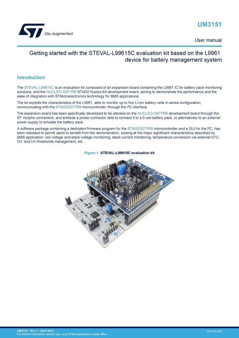
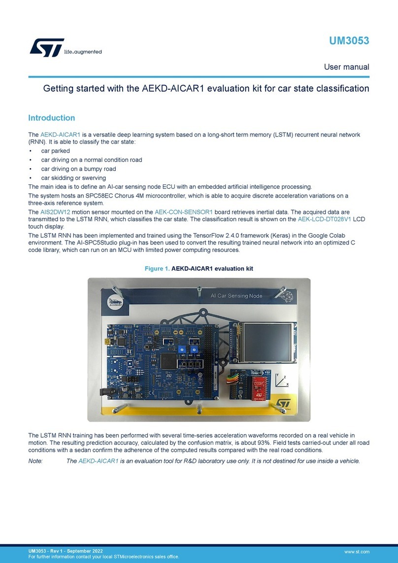
ST STEVAL-IHM020V1 User manual

November 2008 Rev 1 1/23
UM0583
User manual
STEVAL-IHM020V1 demonstration board based on the
STCC08 AC switch failure mode detector
Introduction
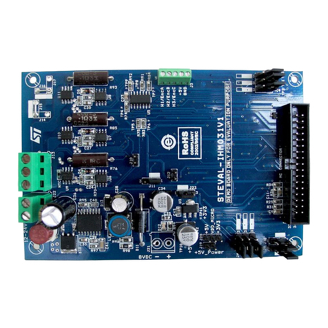
The STEVAL-IHM020V1 demonstration board (see Figure 1) provides a means to evaluate
the performance of the STCC08, which is an AC switch failure mode detector and an AC
power switch driver. The device is dedicated to driving up to 10 mA IGT AC switches (ACS,
ACST and TRIACs), and detecting any switch failures. This solution embeds a switch driver
and an AC switch state detector. It contributes to system safety by monitoring AC switches
driving sensitive loads such as drain pumps, door locks, heaters, cooling fans, and
compressors.
Figure 1. STEVAL-IHM020V1, STCC08 demonstration board
This user manual provides all information needed to set up and operate the demonstration
board. With this demonstration board, you can:
■Evaluate the full ST solution (microcontroller + STCC08)
■Test and analyze the AC switch failure detection features of the STCC08 device
AM01336v1
www.st.com

Contents UM0583
2/23
Contents
1 Demonstration board introduction . . . . . . . . . . . . . . . . . . . . . . . . . . . . . 4
1.1 Package contents . . . . . . . . . . . . . . . . . . . . . . . . . . . . . . . . . . . . . . . . . . . . 4
1.2 Board presentation . . . . . . . . . . . . . . . . . . . . . . . . . . . . . . . . . . . . . . . . . . . 4
2 STCC08 description . . . . . . . . . . . . . . . . . . . . . . . . . . . . . . . . . . . . . . . . . 6
2.1 Block diagram description . . . . . . . . . . . . . . . . . . . . . . . . . . . . . . . . . . . . . 6
2.2 Gate driver . . . . . . . . . . . . . . . . . . . . . . . . . . . . . . . . . . . . . . . . . . . . . . . . . 7
2.3 ACS failure detection . . . . . . . . . . . . . . . . . . . . . . . . . . . . . . . . . . . . . . . . . 7
3 Features . . . . . . . . . . . . . . . . . . . . . . . . . . . . . . . . . . . . . . . . . . . . . . . . . . 10
3.1 ST7LITE39F2 microcontroller . . . . . . . . . . . . . . . . . . . . . . . . . . . . . . . . . 10
3.2 DC capacitive power supply . . . . . . . . . . . . . . . . . . . . . . . . . . . . . . . . . . . 10
4 Using the demonstration board . . . . . . . . . . . . . . . . . . . . . . . . . . . . . . . 12
4.1 Load . . . . . . . . . . . . . . . . . . . . . . . . . . . . . . . . . . . . . . . . . . . . . . . . . . . . . 12
4.2 Measurement points . . . . . . . . . . . . . . . . . . . . . . . . . . . . . . . . . . . . . . . . . 12
4.3 Getting started . . . . . . . . . . . . . . . . . . . . . . . . . . . . . . . . . . . . . . . . . . . . . 13
4.3.1 Procedure . . . . . . . . . . . . . . . . . . . . . . . . . . . . . . . . . . . . . . . . . . . . . . . 13
5 IEC 61000-4-4 Burst immunity test . . . . . . . . . . . . . . . . . . . . . . . . . . . . 16
5.1 Test conditions . . . . . . . . . . . . . . . . . . . . . . . . . . . . . . . . . . . . . . . . . . . . . 16
5.2 Demonstration board immunity test . . . . . . . . . . . . . . . . . . . . . . . . . . . . . 16
5.3 Recommendations for improving application immunity . . . . . . . . . . . . . . 16
6 Conclusion . . . . . . . . . . . . . . . . . . . . . . . . . . . . . . . . . . . . . . . . . . . . . . . . 18
Appendix A STCC08 demonstration board schematic . . . . . . . . . . . . . . . . . . . . 19
Appendix B Bill of materials . . . . . . . . . . . . . . . . . . . . . . . . . . . . . . . . . . . . . . . . . 20

UM0583 List of figures
3/23
List of figures
Figure 1. STEVAL-IHM020V1, STCC08 demonstration board . . . . . . . . . . . . . . . . . . . . . . . . . . . . . . 1
Figure 2. Main components used (top view) . . . . . . . . . . . . . . . . . . . . . . . . . . . . . . . . . . . . . . . . . . . . 4
Figure 3. Main components used (top view) . . . . . . . . . . . . . . . . . . . . . . . . . . . . . . . . . . . . . . . . . . . . 4
Figure 4. STCC08 block diagram description . . . . . . . . . . . . . . . . . . . . . . . . . . . . . . . . . . . . . . . . . . . 6
Figure 5. Application diagram . . . . . . . . . . . . . . . . . . . . . . . . . . . . . . . . . . . . . . . . . . . . . . . . . . . . . . . 6
Figure 6. AC switch failure-detection principle. . . . . . . . . . . . . . . . . . . . . . . . . . . . . . . . . . . . . . . . . . . 8
Figure 7. Measurement points (top layer view) . . . . . . . . . . . . . . . . . . . . . . . . . . . . . . . . . . . . . . . . . 12
Figure 8. STCC08 demonstration board (top view) . . . . . . . . . . . . . . . . . . . . . . . . . . . . . . . . . . . . . . 13
Figure 9. Short-circuit detection. . . . . . . . . . . . . . . . . . . . . . . . . . . . . . . . . . . . . . . . . . . . . . . . . . . . . 15
Figure 10. Diode mode detection. . . . . . . . . . . . . . . . . . . . . . . . . . . . . . . . . . . . . . . . . . . . . . . . . . . . . 15
Figure 11. Open circuit detection. . . . . . . . . . . . . . . . . . . . . . . . . . . . . . . . . . . . . . . . . . . . . . . . . . . . . 15
Figure 12. AVF signal detection. . . . . . . . . . . . . . . . . . . . . . . . . . . . . . . . . . . . . . . . . . . . . . . . . . . . . . 16
Figure 13. STEVAL-IHM020V1 demonstration board schematic diagram. . . . . . . . . . . . . . . . . . . . . . 19

Demonstration board introduction UM0583
4/23
1 Demonstration board introduction
1.1 Package contents
The following items are supplied in this package:
●Demonstration board featuring the STCC08 AC switch failure mode detector
●DVD containing user manual, product presentation and datasheets.
1.2 Board presentation
Figures 2and 3show the board and the main components used.
Figure 2. Main components used (top view)
Figure 3. Main components used (top view)
AM01337v1
AC switch state
visualization
15 W AC load
STCC08
Capacitive
power
supply
AC switch failuressimulation
MCU ST7FLITE39
STCC08
control
ACS108-6S
AM01338v1
SW2 SW3SW1 SW4 SW5
U2
U1
U3D6
D9
D8
D7
D5
J3
J1

UM0583 Demonstration board introduction
5/23
Components on the demonstration board include:
●the STCC08 device (U1)
●the STLITE39F2 MCU (U2). The 8-bit MCU drives the AC switch through the STCC08,
analyzes the STCC08 AVF signals and powers LEDs to indicate AC switch failures
●the ACS108-6S (U3), transient voltage protected AC switch
●A capacitive DC power supply
●An ICC (in-circuit connector) (J3) to load the firmware in the MCU.
Warning: Before the board is connected to a computer through the ICC
connector, ensure that the AC line is connected to the board
through an insulated plug. This is essential to avoid electrical
shock.
●A switch to simulate an AC load failure in open circuit (SW1)
●2 switches (SW2, SW3) to simulate a diode mode failure in both polarities of the AC line
and a short-circuit of the AC switch (when SW2 and SW3 are in the “YES” position at
the same time)
●A switch to simulate an AC switch failure in open circuit (SW4)
●An STCC08 CNTRL switch (SW5). This switch is used to turn the AC switch (ACS) on
or off through the MCU and the STCC08
●An STCC08 CNTRL LED (D5), used to see whether or not the AC switch has been
controlled by the user
●LEDs to define the ACS state
– A “DIODE” LED (D6) to visualize an ACS failure in diode mode in both AC line
cycles. The LED is on if the AC switch fails in diode mode.
– An “OPEN” LED (D7) to indicate an ACS failure in open circuit. This LED is on if
the AC switch is damaged in open circuit
– A “CC” LED (D8) to show an ACS failure in short-circuit on both polarities of the
AC line. This LED is on if the AC switch is damaged in short-circuit
– An “ON” LED (D9) to indicate that the AC switch is on
●Test points to allow the connection of voltage probes:
– L (TP2) and N (TP1): line and neutral of the AC line
– VCC (TP3): positive power supply
– GND (TP4): power supply reference
– ZVS (TP5): zero crossing of the AC line voltage
– OUT (TP6): anode of the ACS
– AC (TP7): ACS status sense input
– AVF (TP8): alternating voltage feedback. ACS status output
– ON/OFF (TP12): “STCC08 CNTRL” switch state, used to turn on or off the ACS
through the MCU and the STCC08
– IN (TP9): STCC08 IN input used to control the ACS
●An AC line connector (J1)
●An AC load: light bulb (15 W at 230 VRMS).
For more detailed information, please refer to the schematic diagram in Appendix A.
STCC08 description UM0583
6/23
2 STCC08 description
2.1 Block diagram description
Figure 4 shows the block diagram of the STCC08. It includes a “gate driver” block to control
the AC switch, a “power switch signal shaping” block used to read the AC switch state and a
buffer able to send the AC switch state to the MCU (AVF DRIVER). This signal should be
analyzed by the MCU, which can power-off the application in hazardous situations (for
example, to open a relay (SW) placed in the front-end of the application - see Figure 5).
Table 1 provides the pin definitions of the STCC08.
Figure 4. STCC08 block diagram description
Figure 5. Application diagram
Note: The STCC08 AVF driver block is used to send the AC switch state to the MCU. The AVF
output is an open collector and should be loaded with an external resistor or connected
directly to the MCU, in pull-up input configuration.
AM01339v1
AVF
V
CC
GND
R
IG
AC
IN
G
POWER SWITCH
SIGNAL SHAPING
AVF DRIVER
GATE DRIVER
+
-
AVF
GND
STCC08
STCC08
AC
R
IG
G
AVF
IN GND
V
CC
NC
SO-8
1
2
3
4
8
5
6
7
AM01340v1
AVF
V
CC
GND
R
IG
AC
IN
G
POWER SWITCH
SIGNAL SHAPING
GATE DRIVER
+
-
MCU
V
CC
V
CC
V
CC
AVF
GND
LOAD
NEUTRAL
STCC08
STCC08
RShunt
RAC
R
IG
LINE
FRONT END RELAY
AVF
V
CC
GND
R
IG
AC
IN
G
P
O
W
E
R
S
W
I
T
C
H
S
I
G
N
A
L
S
H
A
P
I
N
G
G
A
T
E
D
R
I
V
E
R
+
-
S
T
C
C
0
8
S
SS
T
T
T
C
CC
C
C
C
0
00
8
8
8
POWER SWITCH
SIGNAL SHAPING
AVF DRIVER
GATE DRIVER
+
-
MCU
V
CC
= 3.3V to 5 V
V
CC
V
CC
AVF
GND
LOAD
NEUTRAL
ACS
STCC08
STCC08
RShunt
RAC
R
IG
LINE
FRONT END RELAY
SW

UM0583 STCC08 description
7/23
2.2 Gate driver
The STCC08 can control up to 10mA IGT TRIACs, ACST and ACS through a “GATE
DRIVER” block designed:
●to drive the AC switch according to the IN control input state:
– For IN = “1” = VCC: AC switch turn on
– For IN = “0” = GND: AC switch turn off
●to regulate the gate current of the AC switch, thanks to the internal current controller
2.3 ACS failure detection
External resistors (R1, R2, R3 and R4) sense the voltage across the ACS. Using these
resistors, the STCC08 constantly monitors the ACS state. Knowing the STCC08 IN input
state, the ACS state can be deduced by analyzing the AVF signal. Figure 6 gives the ACS
state according to the AVF signal state and the IN signal state.
Table 1. STCC08 pin definition
Pin Symbol Type Description
1 IN Signal AC switch drive
2 AVF Signal Alternating voltage feedback: AC switch state output
3 NC Not connected
4 AC Signal AC switch state sense input
5 VCC Power Positive power supply
6 G Signal AC switch gate driver output
7 RIG Signal AC switch gate current setting
8 GND Power Power supply reference

STCC08 description UM0583
8/23
Figure 6. AC switch failure-detection principle
AM01341v1
ACSstate: OFF if IN=0 (GND) or failed in open circuit if IN=1 (VCC)
ACSstate: ON if IN=1 (VCC) or failed in short circuit if IN=0 (GND)
ACSstate: failed in positive diode mode circuit if IN=0 (GND)
ACSstate: failed in negative diode mode if IN=0 (GND)
VCC
R
AVF
VCC
V
AVF
STCC08
V
AVF
AVF
V
AC
I
Load
AC
VCC/COM
RAC
AC switch
Load
Line
I
Load
RShunt
VCC
R
AVF
VCC
V
AVF
STCC08
V
AVF
AVF
V
AC
I
Load
AC
VCC/COM
RAC
AC switch
Load
Line
I
Load
RShunt
V
AC
VCC
V
AVF
V
AC
I
Load
VCC/COM
RAC
Load
Line
I
Load
RShunt
AC switch
VCC
R
AVF
STCC08
V
AVF
AVF
AC
VCC
V
AVF
V
AC
I
Load
VCC/COM
RAC
Load
Line
I
Load
RShunt
AC switch
VCC
R
AVF
STCC08
V
AVF
AVF
AC
V
AC
VCC
V
AVF
V
AC
ILoad
VCC/COM
RAC
Load
Line
ILoad
RShunt
AC switch
VCC
R
AVF
STCC08
V
AVF
AVF
AC
VCC
V
AVF
V
AC
ILoad
VCC/COM
RAC
Load
Line
ILoad
RShunt
AC switch
VCC
R
AVF
STCC08
V
AVF
AVF
AC
VAC
VCC
V
AVF
V
AC
I
Load
VCC/COM
RAC
Load
Line
I
Load
RShunt
AC switch
VCC
R
AVF
STCC08
V
AVF
AVF
AC
VCC
V
AVF
V
AC
I
Load
VCC/COM
RAC
Load
Line
I
Load
RShunt
AC switch
VCC
R
AVF
STCC08
V
AVF
AVF
AC
V
AC

UM0583 STCC08 description
9/23
Table 2 gives the AC switch state according to the AVF signal and the MCU control (IN).
Knowing the IN signal state, the MCU is able to define the AC switch state by analyzing the
AVF signal. According to the failure mode, the MCU can place the system in a safe
configuration by switching off the home appliance front-end relay.
Note: “If the AC switch is damaged in short-circuit: the ‘CC’ LED is ON (D8)”
“f the AC switch is damaged only in one direction (diode mode): the ‘DIODE’ LED is ON
(D6)”
Table 2. AVF output definition
STCC08 control (IN) AVF signal AC switch states
0+V
CC (except at each zero crossing of the AC line) OFF (no failure)
0 Toggle from +VCC to 0 Diode mode
0 0 Short-circuit
1 0 ON (no failure)
1+V
CC (except at each zero crossing of the AC line) Open circuit

Features UM0583
10/23
3 Features
3.1 ST7LITE39F2 microcontroller
The 8-bit MCU used in this board is the ST7LITE39F2. It belongs to the ST7 family of
microcontrollers, and offers a large number of features at minimum cost.
●The peripheral hardware requirements are reduced to a minimum:
– No quartz or external resonator is used. Instead, an internal RC-oscillator in the
ST7LITE3 is used to generate the clock
– No external RESET circuit is used
●In the MCU firmware, four options must be set:
– Software watchdog activation
– RC oscillator selection
– PLL disabled
– Low voltage detection selection
Note: The MCU firmware has been developed only to evaluate the STCC08 device and is not
compliant with the class B (IEC60335-1 Ed4) requirements.
3.2 DC capacitive power supply
A DC capacitive power supply is used on the board. One peculiarity of this DC power supply
is that it is “negative”. The VCC terminal is connected to neutral. This means that the GND
voltage is 5 V below neutral. Such a connection is mandatory to drive the ACS. Indeed, the
ACS can only be triggered by a negative current (i.e. sourced from the gate). The maximum
average current absorbed by the board is about 44 mA (see Table 3). In this case, a 2.2 µF
C16 capacitor value has been used to ensure that the board works correctly in the worst
application conditions (230 V/110 VRMS line voltage ± 10% and VCC ± 10%).
Note that a 43.2 ΩRIG resistor (R23) value is used. In this case, the minimum ambient
temperature must be 0 °C in order to work correctly the board. For lower ambient
Table 3. Maximum average current sunk by the board
Device Average
current
consumption Comments
MCU 2.5 mA Maximum supply current in run mode. FCPU=1 MHz and VCC=5.5 V
LEDs (two LEDs maximum
can be ON at the same time) 15 mA LED STCC08 controlled
LEDs visualizing the ACS failure
R19=R20= R21= R22=475 Ω ± 1%
Maximum current consumed
by STCC08 (include the gate
current of the ACS) 26 mA VCC_MAX=5.5 V, temperature = 0° C
RIG = 43.2 ± 1% (R23)
Others (mechanical switch) 0.5 mA VCC_Max=5.5 V
Total 44 mA

UM0583 Features
11/23
temperatures, please refer to application note AN2716 to redefine the RIG resistor, and
STCC08 consumption to redefine the C16 capacitor value.
To reduce the surge current when the board is powered, a 39 ΩR14 resistor is connected in
series with the C16 capacitor. Moreover, note that for 110 VRMS AC line voltage, the VCC
decreases (3.8 V), but the STCC08 demonstration board remains completely functional.
The minimum power supplied to the STCC08 must be higher than 3.3 V.

Using the demonstration board UM0583
12/23
4 Using the demonstration board
4.1 Load
The ACS included in the board can withstand a 0.8 A RMS permanent current up to an
ambient temperature of 80 °C. The switch can drive common washing-machine AC loads
without difficulty. In this demonstration board, a light bulb is used to simulate an AC load.
4.2 Measurement points
Figure 7 shows where the test points are located on the board. Table 4 gives the
measurement point definitions.
Figure 7. Measurement points (top layer view)
Table 4. Measurement points
Footprint name Description
L (TP2) Line
N (TP1) Neutral
OUT (TP6) Anode of the ACS
VCC (TP3) DC power supply (also connected to ACS cathodes)
GND (TP4) GND power supply
ON/OFF (TP12) STCC08 control status
ZVS (TP5) Zero voltage signal at MCU input
AVF (TP8) ACS status output connected to MCU input
AC (TP7) AC switch status sense input
IN (TP9) STCC08 input driving the ACS
AM01342v1
TP3
TP9
TP4 TP8
TP2
TP7
TP5
TP6
TP1
TP12

UM0583 Using the demonstration board
13/23
4.3 Getting started
Warning: The demonstration board is not electrically isolated from the
AC input. The MCU is directly linked to the mains voltage. No
insulation is ensured between the accessible parts and the
high voltage. The STCC08 demonstration board must be used
with care and only by persons qualified to work with
electricity at mains voltage levels.
Any measurement equipment must be isolated from the mains before powering the board.
To use an oscilloscope with the demonstration board, it is safer to isolate it from the AC line.
This prevents electric shocks which can occur as a result of touching any single point in the
circuit, but does not prevent shocks when touching two or more points in the circuit.
There is no insulation varnish on solder points. Care should be taken when performing
measurements (for example, voltage probes must be connected only when the line and the
power supply voltages are removed).
4.3.1 Procedure
Figure 8 shows the board and the main components used.
Figure 8. STCC08 demonstration board (top view)
AM01343v1
SW2 SW3SW1 SW4 SW5
U2
U1
U3
D6
D9
D8
D7
D5
J3
J1

Using the demonstration board UM0583
14/23
●To operate the STCC08 board correctly and at each test, perform the following
procedure first:
– Place the “STCC08 CNTRL” switch (SW5) to the “OFF” position
– Set the “N DIODE MODE (SW2)” and “P DIODE MODE (SW3)” switches to the
“NO” position
– Put the “OPEN LOAD” (SW1) switch in the “NO” position
– Set the “OPEN ACS” (SW4) switch to the “NO” position
– Connect the AC mains wire to the AC line connector (J1).
– In this case, all LEDs must be off
●To turn on the AC switch:
– Place all mechanical switches (SW1, SW2, SW3 and SW4) in the “NO” position
– Put the “STCC08 CNTRL” switch (SW5) in the “ON” position
– The “STCC08 CNTRL” LED (D5) and the “ON” LED (D9) must be on
– The light bulb must be on
●To simulate a diode mode of the ACS:
– Set the “N DIODE MODE” (SW2) or “P DIODE MODE” (SW3) switch to the “YES”
position, SW1and SW4 to the “NO” position and SW5 to the “OFF” position
– In this case, the “DIODE” (D6) LED is on
●To simulate a short-circuit of the ACS:
– Put the “N DIODE MODE” (SW2) and “P DIODE MODE” (SW3) switches in the
“YES” position, SW1and SW4 in the “NO” position and SW5 in the “OFF” position
– In this case, the “CC” LED (D8) is on
●To simulate an open circuit of the ACS:
– Place the “STCC08 CNTRL” switch (SW5) in the “ON” position and all mechanical
switches (SW1, SW2, SW3 and SW4) in the “NO” position
– Put the “OPEN ACS” (SW4) switch in the “ON” position
– In this case, the “OPEN” LED (D7) and “STCC08 CNTRL” LED (D9) is on
●To simulate AC switch failures in any AC load state:
– Place the “OPEN LOAD” (SW1) switch in the “YES” position (this disconnects the
AC load) and use the previous procedures to see the AC switch (ACS) state is
detected whatever the AC load state (AC load connected or disconnected)
●Read the “AVF” test point (TP8) with an oscilloscope connected through an insulated
plug (see example in Figure 9, 10 and 11).

UM0583 Using the demonstration board
15/23
Figure 9. Short-circuit detection
Figure 10. Diode mode detection
Figure 11. Open circuit detection
AM01344v1
Q1
Q4
Q2
Q3
Q5 Q6
IN
AVF
AC Line
I
Load
AM01345v1
Q1
Q4
Q2
Q3
Q5 Q6
IN
AVF
AC Line
I
Load
AM01346v1
Q1
Q4
Q2
Q3
Q5 Q6
IN
AVF
AC Line
I
Load

IEC 61000-4-4 Burst immunity test UM0583
16/23
5 IEC 61000-4-4 Burst immunity test
5.1 Test conditions
●Ambient temperature: 25 °C
●Relative humidity: 35%
●Test performed in accordance with IEC 61000-4-4
5.2 Demonstration board immunity test
The AC line input X2 capacitor C15 (10 nF) is used to help avoid triggering the AC switch
(ACS108-6S). The MCU program reads the AVF signal at each AC line peak voltage (see
Figure 12). The AC switch state detection is deducted if the AVF signal remains at the same
level for three consecutive AC line cycles.
Figure 12. AVF signal detection
The demonstration board and mains wires are placed 10 cm above the ground reference.
The mains wire is shorter than 1 m. Each operating cycle has been tested (load OFF and
ON). The burst withstanding level is higher than 4 kV without spurious triggering of the ACS
or ST7Lite3 MCU loss, whatever the coupling mode (to L, N, PE, etc.).
5.3 Recommendations for improving application immunity
To improve application EMC performance, the software must be EMC-oriented (for more
information please refer application note AN1015):
●Auto-recovery routine. At each RESET interrupt, the program must check if the data in
the RAM are stored as scheduled. Indeed, a RESET can occur without the supply
voltage having fallen below VRM (data retention parameter). In this case, a complete
startup is not necessary, and the program can continue working with the previous RAM
Z
V
S
V
AC
TIMER
Z
VS detection => TIMER O
N
Z
VS delay
> T/4 ms
T/2 ms
R
EAD AVF and TIMER OF
F
R
EAD AVF and TIMER OF
F
Z
VS detection => TIMER O
N
Z
VS delay
AM00149v1

UM0583 IEC 61000-4-4 Burst immunity test
17/23
data. This maintains the previous switch state, for example, when a RESET occurs due
to an EMI problem. If, when checked, the RAM registers are not as expected, a
complete initialization procedure is launched. If the RAM area is adequate, then a
“smart reset” can be performed. Only the registers which are used to store internal sub-
routine variables are cleared, and only the main registers keep their previous values
(AC switch status, AC switch control, etc)
●Use the watchdog properly. Enable the watchdog as soon as possible after reset and
never refresh the watchdog in an interrupt routine
●Secure the unused program memory area. Fill the unused memory locations with code
that forces a watchdog reset or jumps to a known program location if you do not want to
generate a reset
●Input filtering. Its recommended to read the AVF signal during several AC line cycles.

Conclusion UM0583
18/23
6 Conclusion
The STEVAL-IHM020V1 demonstration board has been developed to:
●Demonstrate the STCC08 failure-detection capabilities
●Show how to connect the STCC08 to an MCU (non-insulated version)
●Give the user the opportunity to evaluate a full ST solution (microcontroller + STCC08).
This user manual is intended to help home appliance designers test and evaluate the
STCC08 AC switch failure mode detector using the demonstration board.

UM0583 STCC08 demonstration board schematic
19/23
Appendix A STCC08 demonstration board schematic
Figure 13. STEVAL-IHM020V1 demonstration board schematic diagram
AM01347v1
LS
C4
10n/16V
D9
ON
TP9
IN
IN_MCU
R17
0
+
C1
2200uF/25V
C6
10n/16V
R15
680k
TP7
AC
C2
100n/16V
F1
FUSE/1A
R11
68k
R12
68k
C7
100n/16V
D8
CC
D1
5V6 - 0.5W
1 2
R14
39 - 6W
C16
2.2uF - X2
D2
1N4148
D7
OPEN
C15
10n - X2
D6
DIODE
R24
1.2K
C14
100n
U3
ACS
Varistor 375V
R13
IN_MCU
COM/VCC
COM/VCC
R3
56k
R4
56k
C11
10n
C12
10n
Gate
C8
120n/16V
C10
10n
C3
100n/16V
C13
10n
ZVS
STCC08
U1
IN 1
AVF 2
NC 3
AC 4
GND
8
RIG
7
GATE
6
VCC
5
R19
470
R18
470
R23
43
SW4
IN_MCU
AC
TP1
NCOM/VCC
TP12
ON/ OF F
STCC08 CNTRL
R7
56k
AC
C16
1n
TP3
Com/VCC
C5
10n/16V
R8
56k
J1
AC Mains
1
2
3
D3
1N4007
D4
1N4007
SW2
COM/VCC
SW3
R2
56k
R5
56k
Gate
R1
56k
R6
56k
RST
COM/VCC
C9
120n/16V
D5
STCC08 CNTRL
U2
ST7LITE39
PA4(HS) 14
OSC2 19
OSCI/CLKIN 20
PA0(HS) 18
PA1(HS) 17
PA2(HS) 16
PA3(HS) 15
PA5(HS) 13
PB6/ RD I
10 PB5/ AIN5
9PB4/ AIN4
8PB3/ AIN3
7
PB0/ AIN0
4
RST
3
PB1/ AIN1
5
VSS
1
PA7/TDO 11
PB2/ AIN2
6
PA6(HS) 12
VDD
2
COM/VCC
TP5
ZVS
ZVS
R20
470
R21
470
R22
470
COM/VCC
J2
J2 - Light Bulb - 15W
12
SW1
R9
68k
TP6
OUT
R10
68k
J3
INDART CONNECTOR : HE10
1
2
3
4
5
6
7
8
9
10
TP8
AVF
TP4
GND
RST
TP2
L
SW5
R16
0k

Bill of materials UM0583
20/23
Appendix B Bill of materials
Table 5. Bill of material
Ref. Part/value Tolerance
(%) Voltage/
current Watts Technology
information Package footprint
U1 STCC08 SO-8
U2 ST7LITE39FM6 SO-20
U3 ACS108-6S SOT 223
R1, R2, R3,
R4, R5, R6,
R7, R8 56 kΩ5 1/4 W SMD 1206
R9, R10, R11,
R12 68 kΩ5 1/4 W SMD 1206
R14 39 Ω5 > 700 V 6 W Through-hole
R15 680 kΩ5 1/4 W SMD 1206
R16, R17 0 Ω5 1/4 W SMD 1206
R18,R19,R20,
R21, R22 475 Ω5 1/4 W SMD 1206
R23 43.2 Ω 1 0.125 W SMD 1206
C1 2200 µF 20 16 V Radial
electrolytic
C2, C3 100 nF 20 50 V SMD 1206
C8, C9 120 nF 20 SMD 1206
C13 10 nF 20 50 V SMD 1206
C15 10 nF 20 300 V
c.a. X2 Through-hole - pitch: 15 mm
C16 2.2 µF 20 400 V X2 Through-hole -
pitch 27.5 mm
D1 Zener diode
5V6 5V6 0.5 W Through-hole - DO41
D2 Rectifier
1N4148 Through-hole
D3, D4 Rectifier
1N4007 Through-hole
D5, D9 GREEN LED -
CMS CMS TOPLED
D6, D7, D8 RED LED -
CMS CMS TOPLED
J1 Female
connector 3
inputs Pitch: 5,08 mm
Other manuals for STEVAL-IHM020V1
1
Table of contents
Other ST Motherboard manuals

ST
ST STM8L15LPBOARD User manual

ST
ST AEKD-USBTYPEC1 User manual

ST
ST STM32CubeH7 User manual

ST
ST SPC58NG-DISP User manual

ST
ST STM32L476G-EVAL User manual

ST
ST SPC58NHADPT176S User manual

ST
ST STM32F3DISCOVERY User manual

ST
ST STM32746G-EVAL User manual

ST
ST STEVAL-MKI109V2 User manual

ST
ST STM8L1528-EVAL User manual
Popular Motherboard manuals by other brands

Gigabyte
Gigabyte 7VT880-RZ user manual

Angel Medical Systems
Angel Medical Systems Guardian Prog-003 Setup & operation guide

Variscite
Variscite VAR-SOM-MX8X quick start guide

Renesas
Renesas RTKA211630DE0000BU manual

Lanner electronics
Lanner electronics MB-X62 Series manual

austriamicrosystems
austriamicrosystems AS5045 Operation manual