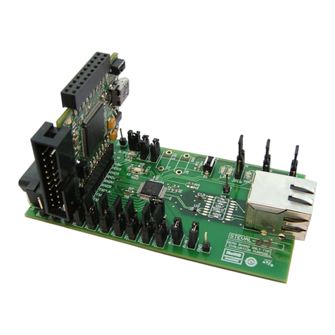
ST STEVAL-MKI005V1 User manual

November 2008 Rev 1 1/37
UM0603
User manual
STEVAL-MKI005V1
demonstration kit for the LIS3LV02DL
Introduction
The STEVAL-MKI005V1 is a demonstration kit designed to provide the user with a
complete, ready-to-use platform to demonstrate the LIS3LV02DL low power 3-axis linear
accelerometer with digital output. The device includes a sensing element and an IC
interface capable of translating information from the sensing element into a measured signal
that can be used for external applications.
In addition to the MEMS sensor, the demonstration board features an ST7-USB
microcontroller that functions as a bridge between the sensor and the PC, on which it is
possible to use the graphical user interface (GUI) downloadable from the web site, or
dedicated software routines for customized applications.
This user manual describes the hardware included with the demonstration kit and provides
the information required to install and run the demonstration kit user interface.
For details regarding the features of the LIS3LV02DL sensor, please refer to the datasheet
for this device and application note AN2381.
www.st.com
www.BDTIC.com/ST

Contents UM0603
2/37
Contents
1 Demonstration kit description . . . . . . . . . . . . . . . . . . . . . . . . . . . . . . . . . 5
2 STEVAL-MKI005V1 GUI installation . . . . . . . . . . . . . . . . . . . . . . . . . . . . . 7
2.1 PC system requirements . . . . . . . . . . . . . . . . . . . . . . . . . . . . . . . . . . . . . . 7
2.2 Software installation . . . . . . . . . . . . . . . . . . . . . . . . . . . . . . . . . . . . . . . . . . 7
2.3 Hardware installation . . . . . . . . . . . . . . . . . . . . . . . . . . . . . . . . . . . . . . . . . 8
3 Graphical user interface . . . . . . . . . . . . . . . . . . . . . . . . . . . . . . . . . . . . . 11
3.1 Connecting to the Virtual COM port . . . . . . . . . . . . . . . . . . . . . . . . . . . . . 12
3.2 “Easy Start” button . . . . . . . . . . . . . . . . . . . . . . . . . . . . . . . . . . . . . . . . . . 12
3.3 “Options” tab . . . . . . . . . . . . . . . . . . . . . . . . . . . . . . . . . . . . . . . . . . . . . . . 13
3.4 “Register Setup” tab . . . . . . . . . . . . . . . . . . . . . . . . . . . . . . . . . . . . . . . . . 14
3.5 “Bars” tab . . . . . . . . . . . . . . . . . . . . . . . . . . . . . . . . . . . . . . . . . . . . . . . . . 15
3.6 “Plot” tab . . . . . . . . . . . . . . . . . . . . . . . . . . . . . . . . . . . . . . . . . . . . . . . . . . 16
3.7 “Data” tab . . . . . . . . . . . . . . . . . . . . . . . . . . . . . . . . . . . . . . . . . . . . . . . . . 19
3.8 “Inclinometer” tab . . . . . . . . . . . . . . . . . . . . . . . . . . . . . . . . . . . . . . . . . . . 20
3.9 “Map Browsing” tab . . . . . . . . . . . . . . . . . . . . . . . . . . . . . . . . . . . . . . . . . 21
3.10 “FFT” tab . . . . . . . . . . . . . . . . . . . . . . . . . . . . . . . . . . . . . . . . . . . . . . . . . 23
3.11 “Interrupt” tab . . . . . . . . . . . . . . . . . . . . . . . . . . . . . . . . . . . . . . . . . . . . . . 23
3.12 “Direction detection” tab . . . . . . . . . . . . . . . . . . . . . . . . . . . . . . . . . . . . . . 24
4 “Data acquisition” quick start . . . . . . . . . . . . . . . . . . . . . . . . . . . . . . . . 26
5 EK Lite . . . . . . . . . . . . . . . . . . . . . . . . . . . . . . . . . . . . . . . . . . . . . . . . . . . 27
6 MEMS pointer . . . . . . . . . . . . . . . . . . . . . . . . . . . . . . . . . . . . . . . . . . . . . 28
6.1 GUI description . . . . . . . . . . . . . . . . . . . . . . . . . . . . . . . . . . . . . . . . . . . . . 28
6.1.1 Left side: main controls . . . . . . . . . . . . . . . . . . . . . . . . . . . . . . . . . . . . . 28
6.1.2 Left side: pointer application controls . . . . . . . . . . . . . . . . . . . . . . . . . . 29
7 Supported commands . . . . . . . . . . . . . . . . . . . . . . . . . . . . . . . . . . . . . . 30
7.1 Getting started . . . . . . . . . . . . . . . . . . . . . . . . . . . . . . . . . . . . . . . . . . . . . 30
7.2 Supported commands . . . . . . . . . . . . . . . . . . . . . . . . . . . . . . . . . . . . . . . 30
www.BDTIC.com/ST

UM0603 Contents
3/37
7.2.1 Start command . . . . . . . . . . . . . . . . . . . . . . . . . . . . . . . . . . . . . . . . . . . . 31
7.2.2 Debug command . . . . . . . . . . . . . . . . . . . . . . . . . . . . . . . . . . . . . . . . . . 31
7.2.3 Stop command . . . . . . . . . . . . . . . . . . . . . . . . . . . . . . . . . . . . . . . . . . . . 31
7.2.4 Register read . . . . . . . . . . . . . . . . . . . . . . . . . . . . . . . . . . . . . . . . . . . . . 31
7.2.5 Register write . . . . . . . . . . . . . . . . . . . . . . . . . . . . . . . . . . . . . . . . . . . . . 32
7.2.6 Single bit write . . . . . . . . . . . . . . . . . . . . . . . . . . . . . . . . . . . . . . . . . . . . 32
7.2.7 Zon and Zoff . . . . . . . . . . . . . . . . . . . . . . . . . . . . . . . . . . . . . . . . . . . . . 32
7.2.8 Device name . . . . . . . . . . . . . . . . . . . . . . . . . . . . . . . . . . . . . . . . . . . . . 32
7.2.9 Firmware version . . . . . . . . . . . . . . . . . . . . . . . . . . . . . . . . . . . . . . . . . . 32
7.3 Quick start . . . . . . . . . . . . . . . . . . . . . . . . . . . . . . . . . . . . . . . . . . . . . . . . 33
8 Schematic diagram . . . . . . . . . . . . . . . . . . . . . . . . . . . . . . . . . . . . . . . . . 34
9 Bill of materials . . . . . . . . . . . . . . . . . . . . . . . . . . . . . . . . . . . . . . . . . . . . 35
10 Revision history . . . . . . . . . . . . . . . . . . . . . . . . . . . . . . . . . . . . . . . . . . . 36
www.BDTIC.com/ST

List of figures UM0603
4/37
List of figures
Figure 1. Demonstration board block diagram. . . . . . . . . . . . . . . . . . . . . . . . . . . . . . . . . . . . . . . . . . . 5
Figure 2. Top silk-screen of the STEVAL-MKI005V1 kit . . . . . . . . . . . . . . . . . . . . . . . . . . . . . . . . . . . 6
Figure 3. Board photograph. . . . . . . . . . . . . . . . . . . . . . . . . . . . . . . . . . . . . . . . . . . . . . . . . . . . . . . . . 6
Figure 4. Software installation . . . . . . . . . . . . . . . . . . . . . . . . . . . . . . . . . . . . . . . . . . . . . . . . . . . . . . . 7
Figure 5. Notify icon. . . . . . . . . . . . . . . . . . . . . . . . . . . . . . . . . . . . . . . . . . . . . . . . . . . . . . . . . . . . . . . 8
Figure 6. Driver installation using the device manager . . . . . . . . . . . . . . . . . . . . . . . . . . . . . . . . . . . . 8
Figure 7. USB driver installation using the hardware update wizard . . . . . . . . . . . . . . . . . . . . . . . . . . 9
Figure 8. Virtual COM driver port assignment . . . . . . . . . . . . . . . . . . . . . . . . . . . . . . . . . . . . . . . . . . 10
Figure 9. Graphical User Interface: main window . . . . . . . . . . . . . . . . . . . . . . . . . . . . . . . . . . . . . . . 11
Figure 10. Options tab . . . . . . . . . . . . . . . . . . . . . . . . . . . . . . . . . . . . . . . . . . . . . . . . . . . . . . . . . . . . . 13
Figure 11. Register setup tab. . . . . . . . . . . . . . . . . . . . . . . . . . . . . . . . . . . . . . . . . . . . . . . . . . . . . . . . 14
Figure 12. Bars tab . . . . . . . . . . . . . . . . . . . . . . . . . . . . . . . . . . . . . . . . . . . . . . . . . . . . . . . . . . . . . . . 15
Figure 13. Bars tab . . . . . . . . . . . . . . . . . . . . . . . . . . . . . . . . . . . . . . . . . . . . . . . . . . . . . . . . . . . . . . . 16
Figure 14. Plot tab . . . . . . . . . . . . . . . . . . . . . . . . . . . . . . . . . . . . . . . . . . . . . . . . . . . . . . . . . . . . . . . . 17
Figure 15. Plot tab - Zoom . . . . . . . . . . . . . . . . . . . . . . . . . . . . . . . . . . . . . . . . . . . . . . . . . . . . . . . . . . 18
Figure 16. Data tab . . . . . . . . . . . . . . . . . . . . . . . . . . . . . . . . . . . . . . . . . . . . . . . . . . . . . . . . . . . . . . . 19
Figure 17. Inclinometer tab . . . . . . . . . . . . . . . . . . . . . . . . . . . . . . . . . . . . . . . . . . . . . . . . . . . . . . . . . 20
Figure 18. Axis inclination . . . . . . . . . . . . . . . . . . . . . . . . . . . . . . . . . . . . . . . . . . . . . . . . . . . . . . . . . . 20
Figure 19. Map Browsing tab. . . . . . . . . . . . . . . . . . . . . . . . . . . . . . . . . . . . . . . . . . . . . . . . . . . . . . . . 21
Figure 20. FFT tab . . . . . . . . . . . . . . . . . . . . . . . . . . . . . . . . . . . . . . . . . . . . . . . . . . . . . . . . . . . . . . . . 23
Figure 21. Interrupt tab . . . . . . . . . . . . . . . . . . . . . . . . . . . . . . . . . . . . . . . . . . . . . . . . . . . . . . . . . . . . 24
Figure 22. Direction detection tab . . . . . . . . . . . . . . . . . . . . . . . . . . . . . . . . . . . . . . . . . . . . . . . . . . . . 25
Figure 23. STEVAL-MKI005V1 lite GUI. . . . . . . . . . . . . . . . . . . . . . . . . . . . . . . . . . . . . . . . . . . . . . . . 27
Figure 24. MEMS pointer demo. . . . . . . . . . . . . . . . . . . . . . . . . . . . . . . . . . . . . . . . . . . . . . . . . . . . . . 28
Figure 25. Schematic diagram of the STEVAL-MKI005V1 board . . . . . . . . . . . . . . . . . . . . . . . . . . . . 34
www.BDTIC.com/ST

UM0603 Demonstration kit description
5/36
1 Demonstration kit description
The STEVAL-MKI005V1 is a complete demonstration kit which allows users to evaluate the
performance of the LIS3LV02DL low power 3-axis linear accelerometer with digital output.
The block diagram of the demonstration kit is shown in Figure 1.
Figure 1. Demonstration board block diagram
The ST7-USB microcontroller included on the board allows communication between the
sensor device and the PC. The user can interact with the hardware either through the GUI
provided with the kit, or through dedicated software routines to run customized applications.
Switches and LED indicators are used to control and monitor the functionality of the board.
The top silk-screen view and photo of the full board, respectively, are shown in Figure 2 and
Figure 3.
ST72F651
SPI
Control Switches
USB USB
Power On LED
Data Ready LED
General Purpose LED
(Left, Right and Reset)
MEMS
Sensor µC Connector
www.BDTIC.com/ST

Demonstration kit description UM0603
6/36
Figure 2. Top silk-screen of the STEVAL-MKI005V1 kit
Figure 3. Board photograph
Operation of the STEVAL-MKI005V1 demonstration kit requires the installation of a
dedicated driver which is included on the installation pack, together with a GUI interface
which allows simple interaction with the sensor. The steps required for driver and software
installation are described in the following section.
www.BDTIC.com/ST

UM0603 STEVAL-MKI005V1 GUI installation
7/36
2 STEVAL-MKI005V1 GUI installation
The installation of the graphical user interface (GUI) for the STEVAL-MKI005V1 requires two
steps:
1. installation on the PC the software downloaded to EK web page.
2. installation of the Virtual COM driver needed to use the demonstration kit board.
2.1 PC system requirements
Both the hardware and software that compose the STEVAL-MKI005V1 demonstration kit
have been designed to operate with Microsoft®Windows XP and Microsoft®Windows Vista.
2.2 Software installation
To install the software downloaded to EK web page:
1. double-click on “Setup.exe”
2. follow the on screen instructions (Figure 4)
Figure 4. Software installation
www.BDTIC.com/ST

STEVAL-MKI005V1 GUI installation UM0603
8/36
2.3 Hardware installation
To install the virtual COM driver, insert the demonstration kit board into a free USB port. The
“Notify” icon should appear as in Figure 5.
Figure 5. Notify icon
If the “Hardware Update Wizard” window appears (Figure 7), follow the instructions on the
screen. Otherwise, the installation can be performed by following the instructions indicated
in Figure 6 and Figure 7.
Figure 6. Driver installation using the device manager
2
1
Right click on My Computer Right click on “ST MEMS UNIT” and choose Update driver
www.BDTIC.com/ST

UM0603 STEVAL-MKI005V1 GUI installation
9/36
Figure 7. USB driver installation using the hardware update wizard
Once the installation is complete, a COM port number is assigned to the ST Virtual COM
driver (Figure 8). This number should be retained as it is required to run the STEVAL-
MKI005V1 demonstration software GUI. For additional details, see section 3.1.
6
5
3
7
4
www.BDTIC.com/ST

STEVAL-MKI005V1 GUI installation UM0603
10/36
Figure 8. Virtual COM driver port assignment
www.BDTIC.com/ST

UM0603 Graphical user interface
11/36
3 Graphical user interface
To execute the STEVAL-MKI005V1 demonstration software GUI:
1. Click on Start > All Programs
2. Select ST EVAL > STEVAL-MKI005V1 > Executables
3. Launch the program “STEVAL-MKI005V1 Ver. 1.0”
The GUI main window appears as shown in Figure 9.
Figure 9. Graphical User Interface: main window
ref 1
ref 2
ref 4
ref 5
ref 3
www.BDTIC.com/ST

Graphical user interface UM0603
12/36
The functions of the four main sections of the window are described below:
1. “Main Control” (Figure 9, ref 1) - Connects/disconnects the board and starts acquisition
via the Start/Stop buttons
2. “Saving” box (Figure 9, ref 2) - Allows the user to save the data to a specified text file,
choosing the data type to write. Data type available are:
a) RAW: for each axes the software writes the data read directly from the sensor
output registers (OUTX_H, OUTX_L, OUTY_H, OUTY_L and OUTZ_H, OUTZ_L)
b) LSB: the data read directly from the sensor are converted from 2’s complement to
Sign and Magnitude
c) Acceleration: LSB data are multiplied by the sensitivity to obtain the acceleration
expressed in mg
d) Angle: LSB data converted to tilting angle of the board expressed in degrees
e) Interrupt: status of the interrupt
3. “Tab Selector” (Figure 9, ref 3) - Used to toggle between the different functions of the
demonstration kit
4. “Legenda” (Figure 9, ref 4) - In this box is possible to Enable/Disable the axes view
5. “Details” (Figure 9, ref 5) - Shows the details of demonstration kit, the name of sensor,
the version of firmware loaded on microcontroller and the version of PC software
3.1 Connecting to the Virtual COM port
Before using the functions of the demonstration kit software it is necessary to open the
connection with the STEVAL-MKI005V1 board. This is achieved through the following
procedure:
1. connect the STEVAL-MKI005V1 to the desired USB port
2. in the “Select COM” drop-down menu (Figure 9 ref 1), choose the Virtual COM number
to which the board has been mapped. For additional information on how to obtain this
number, see section 2.3
3. open the connection by clicking on “Connect” (Figure 9 ref 1)
At this point the user can acquire, plot and save the acceleration data measured by the
sensor and access the content of the registers embedded in the device.
Clicking the "Find" button (Figure 9 ref 1), the GUI attempts to automatically find the COM
Number assigned to the demonstration kit and shows it in the list box as selected item.
The following sections provide details regarding the functions of the tabs in Figure 9, ref 1.
3.2 “Easy Start” button
When the "Easy Start" button (Figure 9, ref 1) is clicked, the GUI attempts to automatically
find the COM number assigned to the demonstration kit and starts the acquisition.
www.BDTIC.com/ST

UM0603 Graphical user interface
13/36
3.3 “Options” tab
The options tab allows the user to control the following parameters:
1. Full Scale (FS) - Sets the maximum acceleration value measurable by the device. It is
possible to select either 2g or 6g (Figure 10, ref 1)
2. Operating Mode (OM) - This control allows to customer to select the operating mode:
Normal Mode or Power Down Mode (Figure 10, ref 2)
3. Block Data Update (BDU) - this function is used to inhibit output registers update until
both upper and lower register parts are read (Figure 10, ref 3)
4. High-Pass Filter (HP) - This control activates the High Pass Filter on the device and
selects the cut-off frequency (Figure 10, ref 5)
5. Data Rate (DR) - In this box the rate at which each acceleration sample is produced
can be selected. The possible values are 40, 160, 640 or 2560 Hz (Figure 10, ref 5)
6. Tri-State (TS) - Permits switching the SPI lines of the ST7-USB microcontroller
mounted on the demonstration kit between 3-state (i.e. high-impedance) and normal
mode (Figure 10, ref 6). This function makes it possible to isolate the sensor mounted
on the board from the microprocessor, in case any external control (from a different
microcontroller mounted on a separate user board) is needed. This function is inhibited
during the acquisition
7. Big/Little Endian (BLE) - is used to select Big Endian or Little Endian representation for
output registers (Figure 10, ref 7)
8. Data Alignment Selection (DAS) - permits to decide between 12 bit right justified and
16 bit left justified representation of data coming from the device (Figure 10, ref 8)
Figure 10. Options tab
ref 1
ref 2
ref 3
ref 4
ref 5
ref 6
ref 7
ref 8
www.BDTIC.com/ST

Graphical user interface UM0603
14/36
3.4 “Register Setup” tab
The register setup tab shown in Figure 11 allows read/write access to the content of the
registers embedded in the LIS3LV02DL MEMS sensor mounted on the demonstration kit.
The tab is divided into five sections:
1. “General” (Figure 11, ref 1) - Provides access to the registers which control the main
settings of the device. This section contains the control registers (CTRL_REG1,
CTRL_REG2 and CTRL_REG3) and the registers that control the generation of inertial
interrupt signals. It is possible to read and write the contents of each register. To restore
the default value for a given register, press the “Default” button
2. “All Registers” (Figure 11, ref 2) - Permits the user to read, write and recall the default
content for all the registers shown in ref 1 with a single click on the read/write/default
button
3. “Registers Direct Access” (Figure 11, ref 3) - Provides access to any register in the
device. To read a generic register, insert the address in the “Register Address” text box,
then click on the “Read” button. The retrieved content of the register is displayed in the
“Register Value” field. As with writing to a register, the user must specify the address
and the data to be written inside the fields marked “Register Address” and “Register
Value”, respectively, and then press the “Write” button
4. “Load/Save Configuration” (Figure 11, ref 5) - Lets the user save/load a specific
configuration to/from a file
5. “Parameters” (Figure 11, ref 4) - Allows the user to save the register configuration to a
text file, which includes a detailed description of the resulting configuration for each
register
Note: By pressing the "Default" button, the default values for the registers are recalled in the
registers field. To write the values to the registers of the device, the user has to press the
"Write" button after the "Default" one.
Figure 11. Register setup tab
ref 1
ref 2
ref 3
ref 4
ref 5
www.BDTIC.com/ST

UM0603 Graphical user interface
15/36
3.5 “Bars” tab
The bars tab (Figure 12) displays the acceleration data measured by the LIS3LV02DL
sensor in bar chart format. The accelerations along the X, Y and Z axes correspond
respectively to the RED, GREEN and BLUE bars.
The height of each bar is determined by the amplitude of the acceleration signal measured
along the related axis. The full scale of the graph depends on the FS bit in CTRL_REG2 bits
of CTRL_REG4, which may be changed through both the Options (Figure 10, ref 1) and the
Register Setup tabs (Figure 11, ref 1).
Click on the desired bar to zoom: the selected bar is shown at the center of the screen
together with the acceleration as a numerical value. To return to the default view, click on the
center of the bar (Figure 13).
Figure 12. Bars tab
www.BDTIC.com/ST

Graphical user interface UM0603
16/36
Figure 13. Bars tab
3.6 “Plot” tab
The Plot tab (Figure 14)shows the sequence of acceleration samples that have been
measured by the LIS3LV02DL MEMS sensor in the demonstration kit. This tab shows:
1. “Acceleration Value” (Figure 14, ref 1) - Shows the numeric values of the acceleration
samples measured by the sensor
2. “Information” (Figure 14, ref 2) - Legend of the current status. Reported items are the
Operating Mode, Data Rate and Full scale
To zoom in on the waveform, select the desired zone with the left button of the mouse
(Figure 15). Click again with the right button to return to the default view.
www.BDTIC.com/ST

UM0603 Graphical user interface
17/36
Figure 14. Plot tab
ref 1
ref 2
www.BDTIC.com/ST

Graphical user interface UM0603
18/36
Figure 15. Plot tab - Zoom
1) Select one point on the screen
2) Holding the LEFT mouse button
and click the LEFT mouse button
down, move the cursor to obtain
an area on the screen
3) Release the button to terminate
the zoom procedure; a new
area is visible on the screen
4) To return to the previous view,
click on the screen with
the RIGHT mouse button
www.BDTIC.com/ST

UM0603 Graphical user interface
19/36
3.7 “Data” tab
The Data tab (Figure 16) shows the acceleration values measured by the LIS3LV02DL
sensor. The tab is divided into three boxes:
1. “ADC Out” (Figure 16, ref 1) - Displays the acceleration data provided by the sensor
after its conversion from 2’s complement to magnitude and sign
2. “Acceleration Value” (Figure 16, ref 2) - Represents the acceleration data measured by
the sensor, expressed in mg
3. “Angle” (Figure 16, ref 3) - Returns the tilt angle, expressed in degrees, that is inferred
from the “ADC Out” data
Note: To increase data readability, the values shown in the boxes described above are based on
an average of 50 samples.
Figure 16. Data tab
ref 1
ref 2
ref 3
www.BDTIC.com/ST
Table of contents
Other ST Motherboard manuals

ST
ST EVAL-L9960 User manual

ST
ST STM3221G-EVAL User manual

ST
ST PowerSTEP01 EVLPOWERSTEP01 User manual

ST
ST STM3241G-EVAL User manual

ST
ST STEVAL-IDB007V Series User manual

ST
ST EVAL-L99DZ200 User manual

ST
ST NUCLEO-8S207K8 User manual

ST
ST STSW-S2LP-KNX-DK User manual

ST
ST STM3220F-EVAL User manual

ST
ST EVAL-L9958 User manual

ST
ST STSW-STUSB002 User manual

ST
ST STM3210E-EVAL User manual

ST
ST STM32373C-EVAL User manual

ST
ST STM32G4 Nucleo-64 User manual

ST
ST STM32100B-EVAL User manual

ST
ST STM3220G-EVAL User manual

ST
ST STEVAL-IPMM10B User manual

ST
ST STEVAL-PCC001V1 User manual

ST
ST STEVAL-ISB68WA User manual

ST
ST VIPower VIPer22A-E Installation and operating instructions