ST STEVAL-MKI109V2 User manual

November 2014 DocID017768 Rev 4 1/39
39
UM0979
User manual
STEVAL-MKI109V2:
eMotion motherboard for MEMS adapter boards
Introduction
The STEVAL-MKI109V2 (eMotion) is a motherboard designed to provide the user with a
complete ready-to-use platform for the demonstration of MEMS devices mounted on
adapter boards.
The STEVAL-MKI109V2 uses an STM32F103RET6 microcontroller which functions as a
bridge between the sensor on the adapter board and the PC on which it is possible to use
the Unico graphical user interface (GUI) downloadable from the ST website or dedicated
software routines for customized applications.
This user manual describes the hardware included with the demonstration kit and provides
the information required to install the demonstration board and how to upgrade the firmware
of the microcontroller.
For details regarding the features of each sensor, please refer to the datasheet available for
each individual device.
www.st.com

Contents UM0979
2/39 DocID017768 Rev 4
Contents
1 Demonstration kit description . . . . . . . . . . . . . . . . . . . . . . . . . . . . . . . . . 5
2 eMotion board installation . . . . . . . . . . . . . . . . . . . . . . . . . . . . . . . . . . . . 9
2.1 Hardware installation (Windows platforms) . . . . . . . . . . . . . . . . . . . . . . . . 9
2.2 DFU . . . . . . . . . . . . . . . . . . . . . . . . . . . . . . . . . . . . . . . . . . . . . . . . . . . . . 10
2.2.1 DFU on Windows . . . . . . . . . . . . . . . . . . . . . . . . . . . . . . . . . . . . . . . . . . 11
2.2.2 DFU on Linux . . . . . . . . . . . . . . . . . . . . . . . . . . . . . . . . . . . . . . . . . . . . . 11
2.2.3 DFU on Mac OS . . . . . . . . . . . . . . . . . . . . . . . . . . . . . . . . . . . . . . . . . . 12
3 Supported MEMS adapter boards . . . . . . . . . . . . . . . . . . . . . . . . . . . . . 13
4 Supported commands . . . . . . . . . . . . . . . . . . . . . . . . . . . . . . . . . . . . . . 15
4.1 Getting started . . . . . . . . . . . . . . . . . . . . . . . . . . . . . . . . . . . . . . . . . . . . . 15
4.2 Supported commands . . . . . . . . . . . . . . . . . . . . . . . . . . . . . . . . . . . . . . . 15
4.2.1 Commands list and description . . . . . . . . . . . . . . . . . . . . . . . . . . . . . . . 16
4.2.2 Digital output accelerometers: supported commands . . . . . . . . . . . . . . 26
4.2.3 Analog output accelerometers: supported commands . . . . . . . . . . . . . . 27
4.2.4 Digital output gyroscopes: supported commands . . . . . . . . . . . . . . . . . 28
4.2.5 Analog output gyroscopes: supported commands . . . . . . . . . . . . . . . . . 29
4.2.6 Digital output magnetometers: supported commands . . . . . . . . . . . . . . 29
4.2.7 Digital output pressure sensor: supported commands . . . . . . . . . . . . . 30
4.2.8 Digital output humidity sensor: supported commands . . . . . . . . . . . . . . 31
4.3 Quick start . . . . . . . . . . . . . . . . . . . . . . . . . . . . . . . . . . . . . . . . . . . . . . . . 32
5 Schematic diagrams . . . . . . . . . . . . . . . . . . . . . . . . . . . . . . . . . . . . . . . . 33
6 Bill of materials . . . . . . . . . . . . . . . . . . . . . . . . . . . . . . . . . . . . . . . . . . . . 35
7 Revision history . . . . . . . . . . . . . . . . . . . . . . . . . . . . . . . . . . . . . . . . . . . 38

DocID017768 Rev 4 3/39
UM0979 List of tables
39
List of tables
Table 1. Jumper configuration for power-down (PD), self test (ST) and high-pass filter reset (HP) . . 8
Table 2. List of supported MEMS adapter boards . . . . . . . . . . . . . . . . . . . . . . . . . . . . . . . . . . . . . . 13
Table 3. Supported commands list . . . . . . . . . . . . . . . . . . . . . . . . . . . . . . . . . . . . . . . . . . . . . . . . . . 16
Table 4. Returned values for *start command . . . . . . . . . . . . . . . . . . . . . . . . . . . . . . . . . . . . . . . . . 18
Table 5. Returned values for *debug command . . . . . . . . . . . . . . . . . . . . . . . . . . . . . . . . . . . . . . . . 20
Table 6. Digital output accelerometers: supported commands list . . . . . . . . . . . . . . . . . . . . . . . . . . 26
Table 7. Analog output accelerometers: supported commands list . . . . . . . . . . . . . . . . . . . . . . . . . 27
Table 8. Digital output gyroscopes: supported commands list . . . . . . . . . . . . . . . . . . . . . . . . . . . . . 28
Table 9. Analog output gyroscopes: supported commands list . . . . . . . . . . . . . . . . . . . . . . . . . . . . 29
Table 10. Digital output magnetometer: supported commands list. . . . . . . . . . . . . . . . . . . . . . . . . . . 29
Table 11. Digital output pressure sensor: supported commands list . . . . . . . . . . . . . . . . . . . . . . . . . 30
Table 12. Digital output humidity sensor: supported commands list. . . . . . . . . . . . . . . . . . . . . . . . . . 31
Table 13. Bill of materials for STEVAL-MKI109V2 . . . . . . . . . . . . . . . . . . . . . . . . . . . . . . . . . . . . . . . 35
Table 14. Document revision history. . . . . . . . . . . . . . . . . . . . . . . . . . . . . . . . . . . . . . . . . . . . . . . . . . 38

List of figures UM0979
4/39 DocID017768 Rev 4
List of figures
Figure 1. Demonstration board block diagram. . . . . . . . . . . . . . . . . . . . . . . . . . . . . . . . . . . . . . . . . . . 5
Figure 2. Top silkscreen of the eMotion kit . . . . . . . . . . . . . . . . . . . . . . . . . . . . . . . . . . . . . . . . . . . . . 6
Figure 3. Board top view . . . . . . . . . . . . . . . . . . . . . . . . . . . . . . . . . . . . . . . . . . . . . . . . . . . . . . . . . . . 7
Figure 4. Notification message. . . . . . . . . . . . . . . . . . . . . . . . . . . . . . . . . . . . . . . . . . . . . . . . . . . . . . . 9
Figure 5. Virtual COM port assignment . . . . . . . . . . . . . . . . . . . . . . . . . . . . . . . . . . . . . . . . . . . . . . . 10
Figure 6. eMotion board (power supply and USB). . . . . . . . . . . . . . . . . . . . . . . . . . . . . . . . . . . . . . . 33
Figure 7. STEVAL-MKI109V2 eMotion board (STM32F103RET6 and connectors) . . . . . . . . . . . . . 34

DocID017768 Rev 4 5/39
UM0979 Demonstration kit description
39
1 Demonstration kit description
The eMotion is a complete demonstration kit that allows demonstration of both digital and
analog MEMS sensors. Thanks to its DIL 24 connector, a wide range of MEMS adapter
boards can be used.
The block diagram of the demonstration kit is shown in Figure 1.
Figure 1. Demonstration board block diagram
As shown in the Figure 1, the eMotion demonstration kit is based on the STM32F103RET6
microcontroller and can be connected to the PC through the USB bus. Data coming from the
MEMS sensor connected to the board can be read through the PC GUI provided with the kit.
The eMotion also implements the DFU (device firmware upgrade) feature, therefore, in the
case of a new firmware release, it can be reprogrammed without the need to use a
programmer. See www.st.com/mems for new firmware releases.
The eMotion also integrates three general-purpose LEDs, two LEDs connected directly to
the interrupt pins of digital adapters and the power/USB LED. Moreover, the eMotion
integrates three buttons: two are available to the user on a dedicated GPIO of the
microcontroller, while the other is used as reset for the microcontroller.
All the MEMS adapter pins are available on two connectors placed on the board (Figure 2
JP2 and JP3).
The top silkscreen view and image of the full board are shown in Figure 2 and Figure 3
respectively.
$0Y
&RQWURO6ZLWFKHV
UHVHWOHIWULJKW
0(06
GHYLFH
86%
&RQQHFWRU
63,,&
86%
$QDORJ
&RQWUROV
673')6
3RZHU2Q/('
,QWHUUXSW/('V
*HQHUDO3XUSRVH/('V
:LWK')8
)HDWXUH
',/
&RQQHFWRU
$QDORJ
$'&
670)5(7
&

Demonstration kit description UM0979
6/39 DocID017768 Rev 4
Figure 2. Top silkscreen of the eMotion kit
$0Y

DocID017768 Rev 4 7/39
UM0979 Demonstration kit description
39
Figure 3. Board top view
In order to use the eMotion demonstration kit, installation of a dedicated driver is required,
which is included in the installation pack, together with a GUI interface which allows simple
interaction with the sensor. The steps required for driver and software installation are
described in the following sections.
In Figure 3 some main components placed on the top layer of the eMotion kit are
highlighted.
Jumpers JP9 and JP10 (Figure 3, ref 10, ref 11) are used to select the STM32 boot
mode. When the eMotion is used together with MEMS adapters, JP9 and JP10 must
be fitted (see STM32 datasheet for more information).
Jumper J2 (Figure 3, ref 7) can be used to directly supply the board (from 3.5 V to 6 V)
instead of using the USB connector.
Jumper JP1 allows the user to measure the sensor current consumption by connecting
a multimeter in series with its terminals (Figure 3, ref 9).
Jumpers JP4, JP5, and JP6 (Figure 3, ref 8) are used to manually set some features
which are available for just some of the analog MEMS adapters (see Table 1 for more
details). JP4 is used to set the self-test feature, JP5 to handle the power-down pin, and
JP6 to reset the MEMS high-pass filter. When they are fitted on pins 2-3, these
functions are handled by the firmware itself.
AM07758v1
ref 1
ref 4
ref 2 ref 3
ref 6
ref 8 ref 7ref 9
ref 11
ref 12
ref 5
ref 13
ref 10

Demonstration kit description UM0979
8/39 DocID017768 Rev 4
J1 connector (Figure 3, ref 3) can be used to both reprogram the STM32 and to debug
the code through the JTAG or SWD protocols.
Jumper JP7 (Figure 3, ref 4) is used to select either JTAG (JP7 unfitted) or SWD (JP7
fitted) mode.
eMotion also integrates six LEDs and three buttons:
– LED D1 (Figure 3, ref 6) is switched on when the board is power supplied.
– LEDs D2 and D3 (Figure 3, ref 13) are directly connected to the interrupt pins of
the MEMS digital adapters (if available on the sensor mounted on the adapter
board).
– LEDs D4, D5, and D6 (Figure 3, ref 12) are general-purpose LEDs and are used
to indicate firmware states. For example, LED D6 is switched on when a specific
firmware is selected from those available. LED D5 on indicates that the
microcontroller is well configured for communication with the sensor. Finally the
LED D4 blinks according to the sensor data rate selected.
– Button SW3 (Figure 3, ref 1) is used to reset the STM32.
– Button SW1 and SW2 (Figure 3, ref 2 and ref 5) are connected to STM32 GPIOs
and are available to the user.
Table 1. Jumper configuration for power-down (PD), self test (ST) and high-pass filter
reset (HP)
Jumper on 1-2 position Jumper on 2-3 position Jumper unfitted
JP4
ST
logic level 1:
self-test ON
Self-test is handled by the
firmware
logic level 0:
self-test OFF, default
JP5
PD
logic level 1:
power-down mode
Power-down is handled by the
firmware
logic level 0:
normal mode, default
JP6
HP
logic level 1: external
high-pass filter reset
High-pass filter reset is
handled by the firmware
logic level 0:
normal mode, default

DocID017768 Rev 4 9/39
UM0979 eMotion board installation
39
2 eMotion board installation
The software package can be downloaded from the st.com website and includes the
following directory structure:
DRIVER: it contains the installation package for the USB drivers needed to connect the
eMotion board to the PC. No driver is needed on Linux and Mac OS platforms, so this
directory is included in the Windows installation package only.
DFU: it contains the .dfu files and the installation package for the software needed to
upgrade the firmware of the eMotion board.
FIRMWARE: it contains the source code of the firmware of the eMotion board together
with the corresponding binary file that can be flashed to the board using the DFU
software.
The section below describes the procedure to install the driver for the eMotion board
(needed on Windows platforms only) and the DFU software.
2.1 Hardware installation (Windows platforms)
No driver installation is needed on Linux and Mac OS platforms.
To install the STM32 virtual COM port driver on Windows platforms, launch the
“VCPDriver_V1.1_Setup.exe” included in the Windows installation package under the
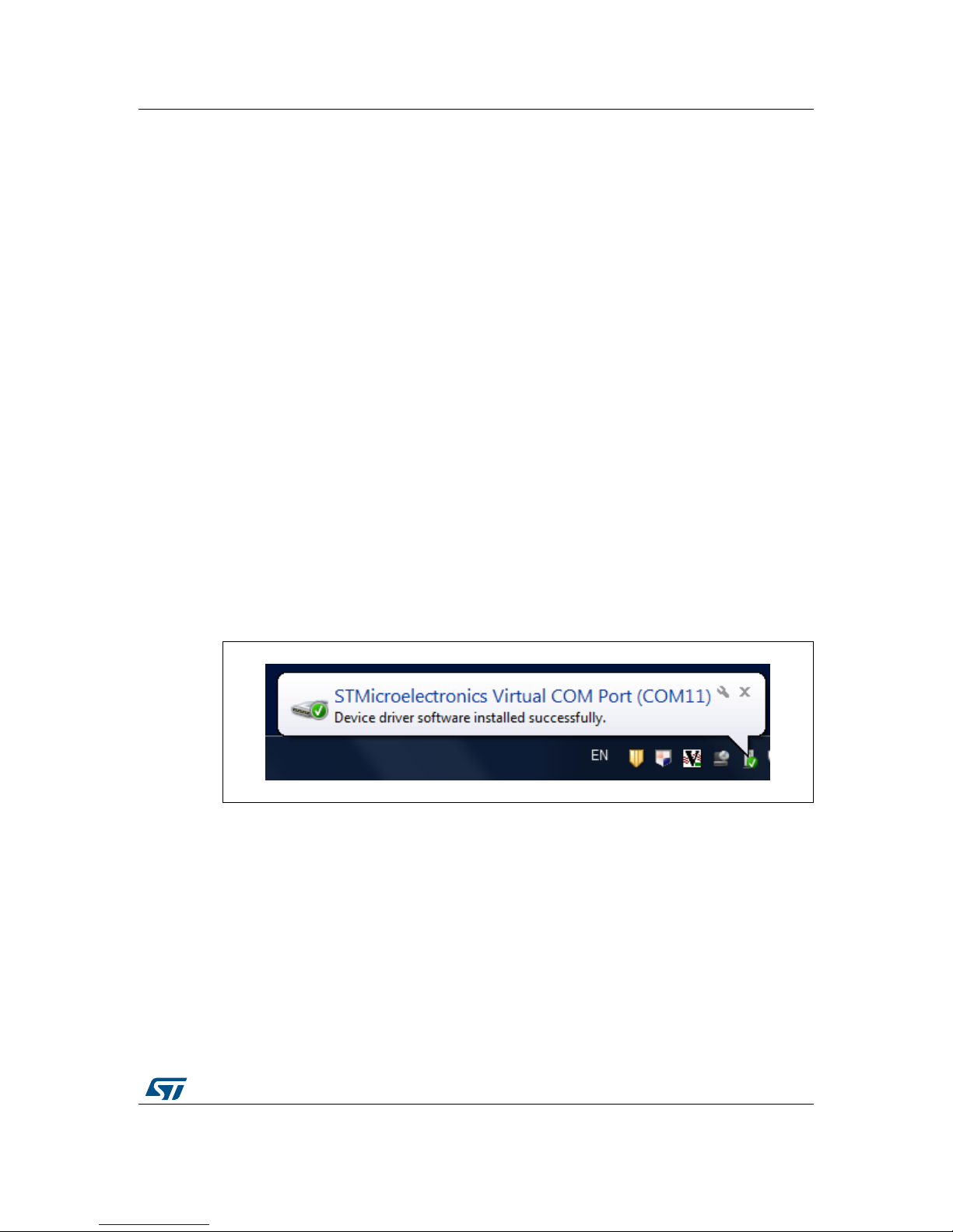
“DRIVER” folder and follow the instructions on the screen. Once the driver is installed, insert
the demonstration kit board into a free USB port. A notification message should appear, as
in Figure 4.
Figure 4. Notification message
Now the eMotion should be recognized by the PC as a virtual COM. In order to confirm
which COM port has been assigned to the board, right click on “My Computer” and select
“Manage”, select “Device Manager” and scroll through the list until “Ports (COM & LPT)”. In
the following example (Figure 5) the COM11 has been assigned to the board.

eMotion board installation UM0979
10/39 DocID017768 Rev 4
Figure 5. Virtual COM port assignment
2.2 DFU
The MEMS STEVAL-MKI109V2 demonstration board is capable of reprogramming an
application through the USB, in accordance with the DFU class specification defined by the
USB Implementers Forum. This capability is useful because it allows reprogramming the
microcontroller directly in the field and is particularly well-suited to USB applications where
the same USB connector can be used both for the standard operating mode and for the
reprogramming process.
In order to configure the eMotion board in DFU mode button SW2 must be pressed before
supplying the board and released when the LEDs D1, D4, D5, and D6 light up.
If the firmware version in use is lower than V3.0.0.0, it’s mandatory to patch the DFU feature
using the “DFU_Patcher_V1.0.2.dfu” file available under the “DFU” folder before proceeding
with the upgrade of the firmware with a version equal to or higher than V3.0.0.0. The
procedure to patch the DFU feature corresponds to the one used during a standard
firmware upgrade with the DFU tool. At the end of this procedure, if the green LED D4 is on,
it indicates that the procedure is successfully completed; if the red LED D5 is on, the
procedure failed and has to be repeated. Before proceeding with the new firmware upgrade
the board must be reset using the SW3 button.

DocID017768 Rev 4 11/39
UM0979 eMotion board installation
39
2.2.1 DFU on Windows
To install the DFU software, launch the “DfuSe_Demo_V3.0_Setup.exe” included in the
software package under the “DFU” folder and follow the instructions on the screen. To
launch the software, select “Start > STMicroelectronics > DfuSe > DfuSe Demonstration”.
In the ‘Upgrade or Verify Action’ section of the Dfuse Demo tool click on the ‘Choose...’
button and select the target .dfu file; then click the ‘Upgrade’ button to start the firmware
upgrade.
For more details regarding DFU and the microcontroller ST GUI, see the related user
manual located under “Start > STMicroelectronics > DfuSe > Docs > DfuSe Getting Started”.
2.2.2 DFU on Linux
The DFU program used for Linux operating systems is ‘dfu-util’.
The procedure for Ubuntu Linux operating systems is described below.
To install this program, open a terminal and write the following command (with sudo to
ensure having the correct permissions):
sudo apt-get install dfu-util
Create a udev rules file:
sudo gedit /etc/udev/49-emotion.rules
and fill it with the following content:
# 0483:5740 - STM32F4 in USB Serial Mode (CN5) ATTRS{idVendor}=="0483",
ATTRS{idProduct}=="5740", ENV{ID_MM_DEVICE_IGNORE}="1"
ATTRS{idVendor}=="0483", ATTRS{idProduct}=="5740", ENV{MTP_NO_PROBE}="1"
SUBSYSTEMS=="usb", ATTRS{idVendor}=="0483", ATTRS{idProduct}=="5740",
MODE:="0666"
KERNEL=="ttyACM*", ATTRS{idVendor}=="0483", ATTRS{idProduct}=="5740",
MODE:="0666"
# 0483:df11 - STM32F4 in DFU mode (CN5) SUBSYSTEMS=="usb",
ATTRS{idVendor}=="0483", ATTRS{idProduct}=="df11", MODE:="0666"
Tell udev to reload its rules:
sudo udevadm control --reload-rules
You should now be able to program the board. So, connect the eMotion board in DFU mode,
and run the following command:
sudo dfu-util -a 0 -D dfu_path/file.dfu -d 0483:df11
where dfu_path and file.dfu are the path to the dfu file and the dfu file name respectively
(example: sudo dfu-util -a 0 -D Desktop/eMotionV2_REL_4_0.dfu -d 0483:df11).

eMotion board installation UM0979
12/39 DocID017768 Rev 4
To use the board with the upgraded firmware you need to disconnect and reconnect it, in
order to exit DFU mode.
2.2.3 DFU on Mac OS
The DFU program used for Mac operating systems is ‘dfu-util’. Before installing it, you need
to install Homebrew. To do that, you need to open a terminal and run the following
command:
ruby -e "$(curl -fsSL https://raw.github.com/Homebrew/homebrew/go/install)"
Once Homebrew is installed on your Mac, you can install dfu-utils with the following
command:
brew install dfu-util
You should now be able to program the board. So, connect the eMotion board in DFU mode,
and run the following command:
dfu-util -a 0 -D dfu_path/file.dfu -d 0483:df11
where dfu_path and file.dfu are the path to the dfu file and the dfu file name respectively
(example: dfu-util -a 0 -D Desktop/eMotionV2_REL_4_0.dfu -d 0483:df11).
To use the board with the upgraded firmware you need to disconnect and reconnect it, in
order to exit DFU mode.

DocID017768 Rev 4 13/39
UM0979 Supported MEMS adapter boards
39
3 Supported MEMS adapter boards
Table 2 below provides the complete list of supported adapter boards.
Table 2. List of supported MEMS adapter boards
Adapter board Device
STEVAL-MKI009V1 LIS3LV02DL
STEVAL-MKI013V1 LIS302DL
STEVAL-MKI015V1 LIS344ALH
STEVAL-MKI074V1 LY330ALH
STEVAL-MKI075V1 LY3100ALH
STEVAL-MKI076V1 LY3200ALH
STEVAL-MKI082V1 LPY4150AL
STEVAL-MKI083V1 LPY450AL
STEVAL-MKI084V1 LPY430AL
STEVAL-MKI085V1 LPY410AL
STEVAL-MKI086V1 LPY403AL
STEVAL-MKI087V1 LIS331DL
STEVAL-MKI088V1 LIS33DE
STEVAL-MKI089V1 LIS331DLH
STEVAL-MKI090V1 LIS331DLF
STEVAL-MKI091V1 LIS331DLM
STEVAL-MKI092V1 LIS331HH
STEVAL-MKI095V1 LPR4150AL
STEVAL-MKI096V1 LPR450AL
STEVAL-MKI097V1 LPR430AL
STEVAL-MKI098V1 LPR410AL
STEVAL-MKI099V1 LPR403AL
STEVAL-MKI105V1 LIS3DH
STEVAL-MKI106V1 LSM303DLHC
STEVAL-MKI107V1 L3G4200D
STEVAL-MKI107V2 L3GD20
STEVAL-MKI108V1 9AXISMODULE v1 [LSM303DLHC + L3G4200D]
STEVAL-MKI108V2 9AXISMODULE v2 [LSM303DLHC + L3GD20]
STEVAL-MKI110V1 AIS328DQ
STEVAL-MKI113V1 LSM303DLM
STEVAL-MKI114V1 MAG PROBE (based on LSM303DLHC)

Supported MEMS adapter boards UM0979
14/39 DocID017768 Rev 4
STEVAL-MKI120V1 LPS331AP
STEVAL-MKI122V1 LSM330DLC
STEVAL-MKI123V1 LSM330D
STEVAL-MKI124V1 10AXISMODULE [LSM303DLHC + L3GD20+ LPS331AP]
STEVAL-MKI125V1 A3G4250D
STEVAL-MKI133V1 LSM303D
STEVAL-MKI134V1 LIS3DSH
STEVAL-MKI135V1 LIS2DH
STEVAL-MKI136V1 L3GD20H
STEVAL-MKI137V1 LIS3MDL
STEVAL-MKI141V1 HTS221 (I2C i/f only)
STEVAL-MKI141V2 HTS221
STEVAL-MKI142V1 LPS25H
STEVAL-MKI151V1 LIS2DH12
STEVAL-MKI152V1 LIS2DM
STEVAL-MKI153V1 H3LIS331DL
STEVAL-MKI154V1 LSM9DS0
Table 2. List of supported MEMS adapter boards (continued)
Adapter board Device

DocID017768 Rev 4 15/39
UM0979 Supported commands
39
4 Supported commands
The microcontroller mounted on the eMotion board is equipped with dedicated firmware that
supports a set of commands which allow to control either the digital or the analog output
MEMS sensor and permits the acquisition of the measured data. The firmware also handles
the communication between the board and the PC through the USB bus. These features
allow the user to easily write their own applications to exploit the capabilities of the sensor
chosen.
This section describes the commands that are supported by the firmware for the
microcontroller of the eMotion demonstration kit.
4.1 Getting started
Before using the commands supported by the firmware, the following procedure must be
performed:
1. Connect the eMotion to the USB port
2. Launch an application which allows to send commands through the virtual serial port.
The remainder of this document assumes the use of “Microsoft© HyperTerminal”
program available with the Windows XP operating system
3. Create a new connection, enter a name (e.g. “STEVAL-MKI109V2”), and click “OK”
4. In the “Connect Using” field, select the virtual COM port to which the USB port has
been mapped, and click “OK”
5. In port settings, set bits per second to 115200, data bits to 8, parity to none, stop bits to
1, and flow control to none. Click “OK”
6. In the “HyperTerminal” application window choose “files” > “properties” > “settings”,
then click on the “ASCII Setup” button
7. Select “Send line ends with line feeds” and “Echo typed characters locally”
8. Click the “OK” button to close the “ASCII Setup” window
9. Click the “OK” button to close the “Properties” window.
Once this procedure has been completed the user can utilize the commands described in
the following sections by typing them into the “HyperTerminal” window.
4.2 Supported commands
The firmware supports a wide range of MEMS adapters; the next section provides the
complete list of supported commands (see Table 3) and their description.
Then, split into sections, the list of commands available for each sensor supported by the
eMotion firmware is provided.

Supported commands UM0979
16/39 DocID017768 Rev 4
4.2.1 Commands list and description
Table 3. Supported commands list
Command Description Returned value
*setdbXXXVY Selects firmware according to the adapter
connected
*start Starts continuous data acquisition (see Table 4)
*debug Returns the output data in readable text
format (see Table 5)
*stop Stops data acquisition
*Zon Forces 3-state
*Zoff Exits from 3-state
*dev Device name e.g.: LIS3DH
*ver Firmware version e.g.: V1.0
*rAA Accelerometer register read e.g.: RAAhDDh
*wAADD Accelerometer register write
*grAA Gyroscope register read e.g.: GRAAhDDh
*gwAADD Gyroscope register write
*mrAA Magnetometer register read e.g.: MRAAhDDh
*mwAADD Magnetometer register write
*prAA Pressure sensor register read e.g.: PRAAhDDh
*pwAADD Pressure sensor register write
*hrAA Humidity sensor register read e.g.: HRAAhDDh
*hwAADD Humidity sensor register write
*single It gets a single X, Y, and Z data acquisition (see Table 5)
*list Prints the list of MKIs supported e.g.: MKI105V1
*listdev Prints the list of devices supported e.g.: LIS3DH
*echoon Activates the write verbose mode e.g.: RAAhDDh
*echooff Deactivates the write verbose mode
*fiforst Accelerometer “Reset mode” enable st 0 0 0 0 0 0 IR FC FS
*fifomde Accelerometer “FIFO mode” enable st 0 0 0 0 0 0 IR FC FS
*fifostr Accelerometer “FIFO stream” enable st 0 0 0 0 0 0 IR FC FS
*fifostf Accelerometer “Stream to FIFO” enable st 0 0 0 0 0 0 IR FC FS
*fifobtf Accelerometer “Bypass to FIFO” enable st 0 0 0 0 0 0 IR FC FS
*fifobts Accelerometer “Bypass to stream” enable st 0 0 0 0 0 0 IR FC FS
*fifodstr Accelerometer “Dynamic stream” enable st 0 0 0 0 0 0 IR FC FS
*gfiforst Gyroscope “Reset mode” enable st 0 0 0 0 0 0 IR FC FS

DocID017768 Rev 4 17/39
UM0979 Supported commands
39
Note: IR: interrupt byte; FC: FIFO control register; FS: FIFO source register.
Set demonstration board
The command *setdbxxxvy selects the part of the firmware able to handle the adapter board
sensor connected to the board. e.g., in order to select the firmware for the LIS3DH the
command must be: *setdb105V1. The D6 LED (green) is automatically switched on.
*gfifomde Gyroscope “FIFO mode” enable st 0 0 0 0 0 0 IR FC FS
*gfifostr Gyroscope “FIFO stream” enable st 0 0 0 0 0 0 IR FC FS
*gfifostf Gyroscope “Stream to FIFO” enable st 0 0 0 0 0 0 IR FC FS
*gfifobtf Gyroscope “Bypass to FIFO” enable st 0 0 0 0 0 0 IR FC FS
*gfifobts Gyroscope “Bypass to stream” enable st 0 0 0 0 0 0 IR FC FS
*gfifodstr Gyroscope “Dynamic stream” enable st 0 0 0 0 0 0 IR FC FS
*mfiforst Magnetometer “Reset mode” enable st 0 0 0 0 0 0 IR FC FS
*mfifomde Magnetometer “FIFO mode” enable st 0 0 0 0 0 0 IR FC FS
*mfifostr Magnetometer “FIFO stream” enable st 0 0 0 0 0 0 IR FC FS
*mfifostf Magnetometer “Stream to FIFO” enable st 0 0 0 0 0 0 IR FC FS
*mfifobtf Magnetometer “Bypass to FIFO” enable st 0 0 0 0 0 0 IR FC FS
*mfifobts Magnetometer “Bypass to stream” enable st 0 0 0 0 0 0 IR FC FS
*mfifodstr Magnetometer “Dynamic stream” enable st 0 0 0 0 0 0 IR FC FS
*pfiforst Pressure sensor “Reset mode” enable st 0 0 0 0 0 0 IR FC FS
*pfifomde Pressure sensor “FIFO mode” enable st 0 0 0 0 0 0 IR FC FS
*pfifostr Pressure sensor “FIFO stream” enable st 0 0 0 0 0 0 IR FC FS
*pfifostf Pressure sensor “Stream to FIFO” enable st 0 0 0 0 0 0 IR FC FS
*pfifobtf Pressure sensor “Bypass to FIFO” enable st 0 0 0 0 0 0 IR FC FS
*pfifobts Pressure sensor “Bypass to stream” enable st 0 0 0 0 0 0 IR FC FS
*pfifodstr Pressure sensor “Dynamic stream” enable st 0 0 0 0 0 0 IR FC FS
*PDON Set power-down pin
*PDOFF Clears power-down pin
*STON Sets self test pin
*STOFF Clears self test pin
*HPON Sets high-pass filter pin
*HPOFF Clears high-pass filter pin
*FSON Sets full scale pin
*FSOFF Clears full scale pin
Table 3. Supported commands list (continued)
Command Description Returned value

Supported commands UM0979
18/39 DocID017768 Rev 4
Start command
The *start command initiates the continuous data acquisition. When this command is sent to
the device, it returns a string of bytes (plus carriage return and line feed) similar to “st OUT1
OUT2 OUT3 IR BT”.
The first two bytes are always the ASCII char “s” and “t” which correspond to the
hexadecimal values {73h 74h}.
OUT1, OUT2, and OUT3 are the bytes that contain the values measured at device outputs;
if the output data is represented on more than 8 bits, OUT1, OUT2, and OUT3 are split into
two bytes: high byte (e.g.: “XH”) and low byte (e.g.: “XL”).
IR contains the interrupt bytes and BT contains the bytes that describe the state of the
buttons integrated on the board.
Specifically, bit#0 of the “BT” data corresponds to the status of the SW1 button on the
demonstration kit board: it is set to 1 when the SW1 is pressed (otherwise 0). Bit#1 has the
same behavior but is dedicated to the SW2.
Before sending the *start command, the device must be out from 3-state and some registers
must be configured according to user needs, therefore, *start must be preceded by a *zoff
and some “Register Write” commands.
Table 4 shows the format of the string returned for each device when a *start command is
sent.
Table 4. Returned values for *start command
STEVAL # (Device) Returned value
STEVAL-MKI009V1 (LIS3LV02DL)
STEVAL-MKI089V1 (LIS331DLH)
STEVAL-MKI092V1 (LIS331HH)
STEVAL-MKI105V1 (LIS3DH)
STEVAL-MKI107V1 (L3G4200D)
STEVAL-MKI107V2 (L3GD20)
STEVAL-MKI110V1 (AIS328DQ)
STEVAL-MKI125V1 (A3G4250D)
STEVAL-MKI134V1 (LIS3DSH)
STEVAL-MKI135V1 (LIS2DH)
STEVAL-MKI136V1 (L3GD20H)
STEVAL-MKI151V1 (LIS2DH12)
STEVAL-MKI153V1 (H3LIS331DL)
s t XH XL YH YL ZH ZL int1 int2 sw1|sw2 \r \n
STEVAL-MKI013V1 (LIS302DL)
STEVAL-MKI087V1 (LIS331DL)
STEVAL-MKI090V1 (LIS331DLF)
STEVAL-MKI091V1 (LIS331DLM)
STEVAL-MKI152V1 (LIS2DM)
s t X Y Z int1 int2 sw1|sw2 \r \n
STEVAL-MKI088V1 (LIS33DE) s t X Y Z int1 sw1|sw2 \r \n
STEVAL-MKI015V1 (LIS344ALH)
STEVAL-MKI114V1 (MAG PROBE) s t XH XL YH YL ZH ZL sw1|sw2 \r \n
STEVAL-MKI137V1 (LIS3MDL) s t XH XL YH YL ZH ZL int1 sw1|sw2 \r \n

DocID017768 Rev 4 19/39
UM0979 Supported commands
39
Note: XH: X-axis output high byte (same for Y axis, Z axis, P pressure, H humidity, and TEMP
temperature)
XL: X-axis output low byte (same for Y axis, Z axis, P pressure, H humidity, and TEMP
temperature)
Debug command
The *debug command starts the continuous data acquisition in debug mode. When this
command is sent to the board, it returns the output values measured by the device
formatted in a readable text format. The values shown on the screen correspond to the LSB
data shown as a decimal number.
STEVAL-MKI074V1 (LY330ALH)
STEVAL-MKI075V1 (LY3100ALH)
STEVAL-MKI076V1 (LY3200ALH)
STEVAL-MKI082V1 (LPY4150AL)
STEVAL-MKI083V1 (LPY450AL)
STEVAL-MKI084V1 (LPY430AL)
STEVAL-MKI085V1 (LPY410AL)
STEVAL-MKI086V1 (LPY403AL)
STEVAL-MKI095V1 (LPR4150AL)
STEVAL-MKI096V1 (LPR450AL)
STEVAL-MKI097V1 (LPR430AL)
STEVAL-MKI098V1 (LPR410AL)
STEVAL-MKI099V1 (LPR403AL)
s t vrefH vrefL o1H o1L out1H out1L out4H out4L o2H
o2L out2H out2L out5H out5L o3H o3L out3H out3L
out6H out6L sw1|sw2 \r \n
STEVAL-MKI106V1 (LSM303DLHC)
STEVAL-MKI113V1 (LSM303DLM)
STEVAL-MKI133V1 (LMS303D)
s t A_XH A_XL A_YH A_YL A_ZH A_ZL M_XH M_XL
M_YH M_YL M_ZH M_ZL A_int1 A_int2 sw1|sw2 \r \n
STEVAL-MKI108V1 (9AXISMODULEv1)
STEVAL-MKI108V2 (9AXISMODULEv2)
STEVAL-MKI154V1 (LSM9DS0)
s t A_XH A_XL A_YH A_YL A_ZH A_ZL
G_XH G_XL G_YH G_YL G_ZH G_ZL
M_XH M_XL M_YH M_YL M_ZH M_ZL
A_int1 A_int2 sw1|sw2 \r \n
STEVAL-MKI120V1 (LPS331AP) s t PXL PL PH TL TH REF_PXL REF_PL REF_PH
REF_TL REF_TH int1 int 2 sw1|sw2 \r \n
STEVAL-MKI122V1 (LSM330DLC)
STEVAL-MKI123V1 (LSM330D)
s t A_XH A_XL A_YH A_YL A_ZH A_ZL
G_XH G_XL G_YH G_YL G_ZH G_ZL
A_int1 A_int2 G_int1 G_int2 sw1|sw2 \r \n
STEVAL-MKI124V1 (10AXISMODULE)
s t A_XH A_XL A_YH A_YL A_ZH A_ZL
G_XH G_XL G_YH G_YL G_ZH G_ZL
M_XH M_XL M_YH M_YL M_ZH M_ZL
PXL PL PH TL TH REF_PXL REF_PL REF_PH REF_TL
REF_TH A_int1 A_int2 sw1|sw2 \r \n
STEVAL-MKI141V1 (HTS221 - I2C i/f)
STEVAL-MKI141V2 (HTS221) s t HL HH TL TH int1 sw1|sw2 \r \n
STEVAL-MKI142V1 (LPS25H) s t PXL PL PH TL TH REF_PXL REF_PL REF_PH
int1 sw1|sw2 \r \n
Table 4. Returned values for *start command
STEVAL # (Device) Returned value

Supported commands UM0979
20/39 DocID017768 Rev 4
Table 5 shows the format of the string returned for each device when a *debug command is
sent.
Table 5. Returned values for *debug command
STEVAL # (Device) Returned value
STEVAL-MKI009V1 (LIS3LV02DL)
STEVAL-MKI013V1 (LIS302DL)
STEVAL-MKI015V1 (LIS344ALH)
STEVAL-MKI087V1 (LIS331DL)
STEVAL-MKI088V1 (LIS33DE)
STEVAL-MKI089V1 (LIS331DLH)
STEVAL-MKI090V1 (LIS331DLF)
STEVAL-MKI091V1 (LIS331DLM)
STEVAL-MKI092V1 (LIS331HH)
STEVAL-MKI105V1 (LIS3DH)
STEVAL-MKI110V1 (AIS328DQ)
STEVAL-MKI134V1 (LIS3DSH)
STEVAL-MKI135V1 (LIS2DH)
STEVAL-MKI151V1 (LIS2DH12)
STEVAL-MKI152V1 (LIS2DM)
STEVAL-MKI153V1 (H3LIS331DL)
X=XXXXX Y=YYYYY Z=ZZZZZ
STEVAL-MKI082V1 (LPY4150AL)
STEVAL-MKI083V1 (LPY450AL)
STEVAL-MKI084V1 (LPY430AL)
STEVAL-MKI085V1 (LPY410AL)
STEVAL-MKI086V1 (LPY403AL)
STEVAL-MKI095V1 (LPR4150AL)
STEVAL-MKI096V1 (LPR450AL)
STEVAL-MKI097V1 (LPR430AL)
STEVAL-MKI098V1 (LPR410AL)
STEVAL-MKI099V1 (LPR403AL)
VREF=VVVVV OUT1=XXXXX 4OUT1=XXXXX
OUT3=YYYYY OUT6=YYYYY
STEVAL-MKI074V1 (LY330ALH)
STEVAL-MKI075V1 (LY3100ALH)
STEVAL-MKI076V1 (LY3200ALH)
VREF=VVVVV OUT1=XXXXX 4OUT1=XXXXX
STEVAL-MKI106V1 (LSM303DLHC)
STEVAL-MKI113V1 (LSM303DLM)
STEVAL-MKI133V1 (LSM303D)
AX=XXXXX AY=YYYYY AZ=ZZZZZ
MX=XXXXX MY=YYYYY MZ=ZZZZZ
STEVAL-MKI114V1 (MAG PROBE)
STEVAL-MKI137V1 (LIS3MDL) MX=XXXXX MY=YYYYY MZ=ZZZZZ
STEVAL-MKI107V1 (L3G4200D)
STEVAL-MKI107V2 (L3GD20)
STEVAL-MKI125V1 (A3G4250D)
STEVAL-MKI136V1 (L3GD20H)
P=PPPPP R=RRRRR Y=YYYYY
STEVAL-MKI108V1 (9AXISMODULEV1)
STEVAL-MKI108V2 (9AXISMODULEV2)
STEVAL-MKI154V1 (LSM9DS0)
AX=XXXXX AY=YYYYY AZ=ZZZZZ
MX=XXXXX MY=YYYYY MZ=ZZZZZ
GX=XXXXX GY=YYYYY GZ=ZZZZZ
STEVAL-MKI120V1 (LPS331AP)
STEVAL-MKI142V1 (LPS25H) P=PPPPP T=TTTTT
STEVAL-MKI122V1 (LSM330DLC)
STEVAL-MKI123V1 (LSM330D)
AX=XXXXX AY=YYYYY AZ=ZZZZZ
GX=XXXXX GY=YYYYY GZ=ZZZZZ
This manual suits for next models
1
Table of contents
Other ST Motherboard manuals

ST
ST STM32L4R9I-EVAL User manual

ST
ST M24SR-DISCOVERY User manual

ST
ST STA333ML Installation and operating instructions

ST
ST EVAL-L9001 User manual

ST
ST 32L100CDISCOVERY User manual

ST
ST STEVAL-STRKT01 Administrator Guide

ST
ST STEVAL-BLUEMIC-1 User manual

ST
ST STM32100B-EVAL User manual

ST
ST STEVAL-IME015V1 User manual

ST
ST SPC58NHADPT386S User manual

ST
ST STM32091C-EVAL User manual

ST
ST SPC58NHADPT386S User manual

ST
ST PowerSTEP01 EVLPOWERSTEP01 User manual

ST
ST STCC50x1 User manual

ST
ST STEVAL-SPIN3202 User manual

ST
ST STEVAL-BTDP2 User manual

ST
ST EVALSTGAP2S User manual

ST
ST STM32L476ZG User manual

ST
ST SPC584BADPT176S User manual

ST
ST STM32H7B3I-EVAL User manual