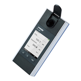
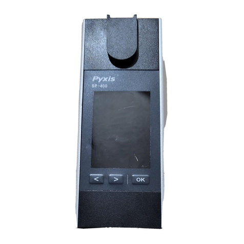
Pyxis SP-400 User manual

Table of Contents
1 Introducon 3
1.1 MainFeatures......................................... 3
2 Specicaons 3
3 Unpacking Instrument 5
3.1 StandardAccessories ..................................... 5
3.2 OponalAccessories ..................................... 5
4 Installaon 5
4.1 BaeryInstallaon ...................................... 5
5 Instrument Overview 6
5.1 ControlKeys.......................................... 6
5.2 MainModuleOn/O ..................................... 7
6 Measurement 7
6.1 PTSA and Conducvity Measurement . . . . . . . . . . . . . . . . . . . . . . . . . . . . 7
6.2 Conducvity Temperature Compensaon . . . . . . . . . . . . . . . . . . . . . . . . . . 8
6.3 High Color and Turbidity Warning . . . . . . . . . . . . . . . . . . . . . . . . . . . . . . . 8
7 Calibraon 9
7.1 PTSA Calibraon (Two-Point with Zero) . . . . . . . . . . . . . . . . . . . . . . . . . . . . 9
7.2 Conducvity Calibraon (500, 1000, 2500, or 5000 µS/cm) . . . . . . . . . . . . . . . . . 11
7.3 User-Dened Conducvity Calibraon . . . . . . . . . . . . . . . . . . . . . . . . . . . . 12
7.4 Combined PTSA and Conducvity Calibraon . . . . . . . . . . . . . . . . . . . . . . . . 14
8 Device Informaon and Diagnosis 15
8.1 Bluetooth Connecon to Devices . . . . . . . . . . . . . . . . . . . . . . . . . . . . . . . 16
8.2 FactoryReset ......................................... 18
9 Use with uPyxis® Mobile App 19
9.1 Download uPyxis® MobileApp................................ 19
9.2 Connecng to uPyxis® MobileApp.............................. 19
9.3 SengScreen......................................... 20
9.4 SystemScreen......................................... 21
10 Use with uPyxis® Desktop App 22
10.1 Install uPyxis® DesktopApp.................................. 22
10.2 Connecng to uPyxis® DesktopApp ............................. 22
10.3SystemScreen......................................... 23
10.4DatalogScreen ........................................ 24
10.5SengScreen......................................... 24

11 Device Maintenance and Precauon 25
11.1 Maintenance Best Pracces and Quick Tips . . . . . . . . . . . . . . . . . . . . . . . . . 25
11.2 Methods to Cleaning the SP-400 . . . . . . . . . . . . . . . . . . . . . . . . . . . . . . . 25
11.3Storage ............................................ 26
12 Contact Us 26

Warranty Informaon
Condenality
The informaon contained in this manual may be condenal and proprietary and is the property of Pyxis
Lab, Inc. Informaon disclosed herein shall not be used to manufacture, construct, or otherwise reproduce
the goods described. Informaon disclosed herein shall not be disclosed to others or made public in any
manner without the express wrien consent of Pyxis Lab, Inc.
Standard Limited Warranty
Pyxis Lab warrants its products for defects in materials and workmanship. Pyxis Lab will, at its opon, repair
or replace instrument components that prove to be defecve with new or remanufactured components
(i.e., equivalent to new). The warranty set forth is exclusive and no other warranty, whether wrien or oral,
is expressed or implied.
Warranty Term
The Pyxis warranty term is thirteen (13) months ex-works. In no event shall the standard limited warranty
coverage extend beyond thirteen (13) months from original shipment date.
Warranty Service
Damaged or dysfunconal instruments may be returned to Pyxis for repair or replacement. In some in-
stances, replacement instruments may be available for short duraon loan or lease.
Pyxis warrants that any labor services provided shall conform to the reasonable standards of technical com-
petency and performance eecve at the me of delivery. All service intervenons are to be reviewed and
authorized as correct and complete at the compleon of the service by a customer representave, or des-
ignate. Pyxis warrants these services for 30 days aer the authorizaon and will correct any qualifying
deciency in labor provided that the labor service deciency is exactly related to the originang event. No
other remedy, other than the provision of labor services, may be applicable.
Repair components (parts and materials), but not consumables, provided during a repair, or purchased
individually, are warranted for 90 days ex-works for materials and workmanship. In no event will the in-
corporaon of a warranted repair component into an instrument extend the whole instrument’s warranty
beyond its original term.
Warranty Shipping
A Repair Authorizaon (RA) Number must be obtained from Pyxis Technical Support before any product can
be returned to the factory. Pyxis will pay freight charges to ship replacement or repaired products to the
customer. The customer shall pay freight charges for returning products to Pyxis. Any product returned to
the factory without an RA number will be returned to the customer. To receive an RMA you can generate a
request on our website at hps://pyxis-lab.com/request-tech-support/.
Pyxis Technical Support
Contact Pyxis Technical Support at +1 (866) 203-8397, [email protected], or by lling out a request for
support at hps://pyxis-lab.com/request-tech-support/.
1 Introducon
The Pyxis SP-400 is a uniquely designed handheld mulmeter that measures both PTSA and conducvity,
simultaneously. It is a cuvee-less device. Less than 5 mL water sample is needed to ll the sample cell for
proper measurement.
1.1 Main Features
The SP-400 includes the following features:
• Simultaneous measurement of the electrical conducvity value and the concentraon of uorescent
tracer PTSA of a water sample.
• Pre-calibrated for measuring PTSA (pyrenetetrasulfonic acid) in the range of 0 to 300 ppb.
• The uorescence PTSA measurement is automacally compensated for sample color and turbidity
interference up to 60 NTU without preltraon.
• Conducvity and PTSA uorescence can be calibrated using a single combined standard through a
user-friendly, menu-driven procedure.
• Large color graphic screen that can be read in direct sunlight.
• A single conducvity calibraon using a single standard covers the whole measurement range of
0–15000 µS/cm.
2 Specicaons
Table 1. PTSA Specicaons
Item Specicaon*
Range 0–300 ppb
Accuracy ±1% or ±1.0 ppb
Resoluon 0.1 ppb
Excitaon Wavelength 365 nm
Emission Wavelength 410 nm
Wavelength Accuracy ±1 nm
Calibraon Soluon Point 0, 100, 200, and 300 ppb
*With Pyxis’s connuous improvement policy, these specica-
ons are subject to change without noce.

Table 2. Conducvity Specicaons
Item Specicaon*
Range 0–15000 µS/cm
Accuracy (Range: 0–20
µS/cm)
±10% or ±0.5 µS/cm
Accuracy (Range:
20–10000 µS/cm)
±1%
Accuracy (Range:
10000–15000 µS/cm)
±2%
Resoluon 1 µS/cm
Time for Stable
Measurement
5 seconds
Calibraon Soluons 500 µS/cm, 1000 µS/cm, 2500 µS/cm, 5000 µS/cm, combined 1000 µS/cm
and 100 ppb PTSA, and user-dened (500–5000 µS/cm)
*With Pyxis’s connuous improvement policy, these specicaons are subject to change without noce.
Table 3. Temperature Specicaons
Item Specicaon*
Range 42–112 °F (5–45 °C)
Accuracy ±1%
Resoluon 0.2 °F (0.1 °C)
Compensaon Method Automac to 25 °C
*With Pyxis’s connuous improvement policy, these
specicaons are subject to change without noce.
Table 4. Other Specicaons
Item Specicaon*
Part Number (P/N) 50211
Display 320 ×240 TFT-LCD, visible under direct sunlight
Power Supply 4 AA alkaline baeries
Typical Baery Life 10,000 measurements
Dimension (L ×W×H) 6.30 ×2.91 ×1.30 inch (160 ×74 ×33 mm)
Weight 0.68 lbs (310 g)†
Operaonal Temperature 40–106 °F (4–41 °C)
Storage Temperature -4–140 °F (-10–50 °C)
Humidity 85% at 106 °F (41 °C)
Enclosure Rang IP67
*With Pyxis’s connuous improvement policy, these specicaons are subject to change
without noce.
†Baeries excluded

3 Unpacking Instrument
Remove the instrument and accessories from the shipping container and inspect each item for any damage
that may have occurred during shipment. Verify that all items listed on the packing slip are included. If any
3.1 Standard Accessories
• Four (4) AA alkaline baeries
• Bluetooth/USB Adapter for Desktop P/N: MA-NEB
• User Manual available online at www.pyxis-lab.com/support.html
3.2 Oponal Accessories
The following oponal accessories can be ordered from Pyxis Customer Service ([email protected]om) or
Pyxis eStore at hps://pyxis-lab.com/shop/.
Table 5. Oponal Accessories
Accessory Name Part Number (P/N)
Pyxis Carrying Case for Handheld Devices 50725
Pyxis 100 ppb PTSA + 1000 µS/cm (KCl) Combined Standard — 500 mL 21004
Pyxis Handheld Cleaning Kit SER-002
4 Installaon
4.1 Baery Installaon
The SP-400 is powered by four alkaline baeries. Typical baery life lasts for 10,000 measurements or 10
months. When the baery capacity is crically low, the SP-400 will display a ”LOW BATTERY” warning for 5
seconds and then automacally turn o.
*NOTE*Do not use rechargeable nickel cadmium (NiCad) or lithium baeries.
Replace the baeries to resume operaon of the SP-400 aer the baery warning. The SP-400 will auto-
macally turn on in the measurement mode aer new baeries are installaon.
The SP-400 baery compartment, shown in Figure 1, is on the back side of the instrument. Baeries are
held in place by a cover secured with two Phillips-head screws.

Figure 1. The SP-400 baery compartment
Install baeries using the following steps:
1. Remove the baery compartment cover by loosening the two screws.
2. Remove old baeries and dispose of them properly.
3. Following the posive and negave terminal signs in the compartment boom, snap four new AA
alkaline baeries rmly into the baery holder.
4. Replace the baery compartment cover and ensure that the sealing O-ring is lying at on the baery
holder.
5. Fasten the two screws.
*NOTE*Failure to properly seat the O-ring may result in water damage to the SP-400.
5 Instrument Overview
5.1 Control Keys
The SP-400 has three control keys, as shown in Figure 2. The le ( ), right ( ), and ok ( ) keys
are used to launch acons indicated on the LCD display directly above the keys. The labels above the keys
indicate the funcon associated with each key and funcons can be changed in dierent operaon modes.

Figure 2.
5.2 Main Module On/O
To turn on the SP-400: Press momentarily and release.
To turn o the SP-400: Press and hold for about three seconds. Release when the LCD display
turns o. The SP-400 turns itself o aer 60 seconds without user interacon detected. This is done to
conserve baery life.
*NOTE*This auto-me o seng may be customized by the user as desired through the
uPyxis® Mobile or Desktop App.
6 Measurement
6.1 PTSA and Conducvity Measurement
When powered on, the SP-400 will default to the PTSA and conducvity measurement mode. The water
sample can be transferred to the sample cell using a pipee or lled directly from a faucet, sample bole,
or sample valve.
*NOTE*Special care should be taken when pouring the sample into the cell to avoid air
bubble entrainment, which can interfere with reading accuracy.
Before beginning a measurement, use the sample water to rinse the sample cell at least three mes. Allow
5–10 seconds for the SP-400 to stabilize. The values will be displayed in white with a blue background
if a stable value is reached (Figure 2). For a sample with conducvity in the range of 100 to 6000 µS/cm,
the measured value should be stabilized in the range of 98–102 to 5940–6060 µS/cm, respecvely. For a
sample containing 100 ppb PTSA, the measured PTSA should be stabilized within the range of 98–102 ppb.
*NOTE*The me required to reach a stable reading may be slightly longer if the water
sample temperature is signicantly dierent than the environmental temperature at which
the SP-400 had been equilibrated (stored).

6.2 Conducvity Temperature Compensaon
The displayed conducvity value is automacally corrected to the nominal value at the reference tempera-
ture 25.0 °C with using the sample temperature measured. The commonly used linear correcon equaon
is used:
Conductivity at 25 °C=Conductivity at Tmeasured
1+0.02(Tmeasured –25) (1)
where Tmeasured is the sample temperature in °C.
6.3 High Color and Turbidity Warning
The SP-400 has extra channels to measure sample turbidity and color to automacally compensate sam-
ple color and turbidity interference. If sample turbidity and color values determined are too high, a PTSA
measurement warning will be displayed. In such a case, the user should lter the sample for PTSA mea-
surement.

7 Calibraon
The SP-400 uorescence PTSA measurement and conducvity measurement can be calibrated separately.
To calibrate PTSA measurement requires the 100, 200, or 300 ppb PTSA standard soluon. A standard with
conducvity value 500, 1000, 2500, or 5000 µS/cm can be used to calibrate conducvity. Oponally, the
user can use a standard with any conducvity value in the range of 500–5000 µS/cm, such as the commonly
used 1412 (or 1413) µS/cm standard, to calibrate the SP-400.
For convenience, the SP-400 can be calibrated using a combined standard with 100 ppb PTSA + 1000 µS/cm
KCl conducvity (PTSA-1010). It is highly recommended to use the PTSA standalone calibraon procedure
if the user desires to achieve higher accuracy for low range PTSA measurements (< 20 ppb). The Combined
PTSA/Conducvity Calibraon procedure yields the PTSA calibraon slope only and does not change the
zero point.
7.1 PTSA Calibraon (Two-Point with Zero)
1. Rinse the sample cell three mes with DI water. Fill the sample cell with DI water.
*NOTE*In emergency, “non-PTSA” water, such as city water, may be used, but re-
calibrate using DI water for the zero step as soon as it is available.
2. Power on the SP-400 by pressing . Allow 5–10 seconds for the SP-400 to stabilize.
3. The unit is acvely reading and displaying both PTSA and Conducvity. The values will be very low if
DI water is used; conducvity value is not crical but PTSA value should be near zero. A low non-zero
value (e.g. 0.2 or 0.4, etc.) is not problemac. (Figure 3).
4. Press P-Cal ( ) to launch the PTSA CALIBRATION screen (Figure 4).
5. Press Zero ( ) to set the zero point.
6. If the calibraon succeeds, a checkmark ( ) and instrucons for the slope calibraon will appear
(Figure 5).
7. Rinse the sample cell three mes with the desired PTSA standard. Fill the sample cell with the desired
PTSA standard.
8. Press Cycle ( ) to cycle between the PTSA standards 100, 200, and 300 ppb (it repeats). Ensure
the value selected matches the desired PSTA standard in the sample cell.
9. Press Slope ( ) to start the slope calibraon.
10. If the calibraon succeeds, a checkmark ( ), a ”Calibraon Success” message will appear (Figure
6). Otherwise, a warning message is displayed.
11. Calibraon is now complete. Press Exit ( ) to return to measurement mode.
*NOTE*If Exit is pressed before the second checkmark appears, the calibraon will
not be completed and must be re-done.

7.2 Conducvity Calibraon (500, 1000, 2500, or 5000 µS/cm)
1. Rinse the sample cell three mes with the desired conducvity standard. Fill the sample cell with the
desired conducvity standard.
2. Power on the SP-400 by pressing . Allow 5–10 seconds for the SP-400 to stabilize (Figure 7).
3. Press C-Cal ( ) to launch the COMBINED CALIBRATION screen (Figure 8).
4. Press ( ) to launch the CONDUCTIVITY CALIBRATION screen.
5. Use ( ) and ( ) to cycle to the desired calibraon. The standard conducvity selecons are
500, 1000, 2500, or 5000 µS/cm. For other conducvity values, see the User-Dened Conducvity
Calibraon secon.
*NOTE*To exit the calibraon procedure enrely, long press Calib ( )
6. Press Calib ( ) to conrm the specic conducvity calibraon desired.
7. The display updates as shown in Figure 9 and the user can choose one of three opons:
(a) Press to start the calibraon, or
(b) Press Cancel ( ) to return to the CONDUCTIVITY CALIBRATION screen, or
(c) Press Exit ( ) to abandon calibraon enrely.
8. Once calibraon begins, the SP-400 reads the sample and displays the value in the Measured secon.
A slight variance from the target is acceptable.
9. The message “Calibraon Success” will appear towards the boom of the display (Figure 10).
10. Calibraon is now complete, long press Calib ( ) to return to measurement mode.
Figure 7. Figure 8.

Figure 9. Figure 10.
7.3 User-Dened Conducvity Calibraon
1. Rinse the sample cell three mes with the desired conducvity standard. Fill the sample cell with the
standard.
2. Power on the SP-400 by pressing . Allow 5–10 seconds for the SP-400 to stabilize (Figure 11).
3. Press C-Cal ( ) to launch the COMBINED CALIBRATION screen (Figure 12).
4. Press ( ) to launch the USER DEFINED CALIBRATION screen (Figure 13).
5. Use -( ) and +( ) to adjust the target conducvity value as desired. Holding a key down scrolls
the values at a faster rate.
6. Press Set ( ) to conrm the target conducvity value.
*NOTE*To exit the calibraon procedure enrely, long press Calib ( )
7. Press Calib ( ) to conrm the specic conducvity calibraon desired.
8. The display updates as shown in Figure 14 and the user can choose one of three opons:
(a) Press to start the calibraon, or
(b) Press Cancel ( ) to return to the USER DEFINED CALIBRATION screen, or
(c) Press Exit ( ) to abandon calibraon enrely.
9. Once calibraon begins, the SP-400 reads the sample and displays the value in the Measured secon.
A slight variance from the target is acceptable.
10. The message “Calibraon Success” will appear towards the boom of the display (Figure 15).
11. Calibraon is now complete, long press Calib ( ) to return to measurement mode.

7.4 Combined PTSA and Conducvity Calibraon
The following steps will calibrate both conducvity at 1000 µS/cm and PTSA at 100 ppb using Pyxis 100 ppb
PTSA + 1000 µS/cm (KCl) Combined Standard (P/N: 21004):
1. Rinse the sample cell three mes with the Combined Standard. Fill the sample cell with the Combined
Standard.
2. Power on the SP-400 by pressing . Allow 5–10 seconds for the SP-400 to stabilize (Figure 16).
3. Press C-Cal ( ) to launch the COMBINED CALIBRATION screen (Figure 17).
4. Press Calib ( ) to conrm the desired calibraon.
5. The display updates as shown in Figure 18 and the user can choose one of three opons:
(a) Press to start the calibraon, or
(b) Press Cancel ( ) to return to the COMBINED CALIBRATION screen, or
(c) Press Exit ( ) to abandon calibraon enrely.
6. Once calibraon begins, the SP-400 reads the sample and displays the value in the Measured secon.
A slight variance from the target is acceptable.
7. If successful, a checkmark ( ) will appear next to the conducvity measurement.
8. Aer a second, another checkmark ( ) will appear next to the PTSA measurement.
9. Finally, the message “Calibraon Success” will appear towards the boom of the display (Figure 19).
10. Calibraon is now complete, long press Calib ( ) to return to measurement mode.
Figure 16. Figure 17.

Figure 18. Figure 19.
8 Device Informaon and Diagnosis
The DEVICE INFORMATION screen is launched when System ( ) is pressed in the measurement mode.
This screen contains the device serial number, soware version, and hardware version (Figure 20). The bat-
tery life as a percentage and the MAC addresses for main module also shown.
Press Diagnosis ( ) to launch the SYSTEM DIAGNOSIS screen where raw measurement data are displayed
(Figure 21). The informaon has no use for normal operaon, but instead is used for device troubleshoong.
Provide an image of both the DEVICE INFORMATION screen and the SYSTEM DIAGNOSIS screen when you
Figure 20. Figure 21.

8.1 Bluetooth Connecon to Devices
The SP-400 uses a built-in Bluetooth Low Energy Connecon (BTLE) to connect wirelessly to a smart phone
via the uPyxis® Mobile App or to a computer via the included Bluetooth Adapter (P/N: MA-NEB) and the
uPyxis® Desktop App. To allow the SP-400 to connect via Bluetooth with other devices follow the steps
below:
1. Power on the SP-400 by pressing .
2. Press System ( ) to launch the DEVICE INFORMATION screen.
3. Press Diagnosis ( ) to launch the SYSTEM DIAGNOSIS screen.
4. Allow 5–10 seconds for the message in the top-right corner of the display change from Starng BTLE...
to BTLE Started (Figure 21).
5. Choose to connect via one of two opons:
(a) The uPyxis® Mobile App (see the Use with uPyxis® Mobile App secon), or
(b) The uPyxis® Desktop App (see the Use with uPyxis® Desktop App secon).
8.1.1 Calibrate an ST-500 Series Probe with the SP-400 via Bluetooth
The SP-400 can be used to verify the result of an inline Pyxis ST-500 Series probe by measuring the sample
water taken from the inline probe sample line. The SP-400 can then be used to calibrate the inline probes
over the Bluetooth connecon. To calibrate an inline probe, follow the steps below:
1. Power on the SP-400 by pressing .
2. Press System ( ) to launch the DEVICE INFORMATION screen.
3. Press Comm ( ) to launch the COMMUNICATION screen (Figure 22).
4. Press Scan ( ) to begin scanning for Bluetooth devices.
5. Discoverable devices will begin to populate on the display with their name and MAC-Address (Figure
23).
6. If more than one device appears in the Device list, press »( ) to cycle through the devices.
7. If no devices or the incorrect device appear in the Device list, press Scan ( ) to re-scan for discov-
erable devices.
8. Press Connect ( ) to begin pairing to the selected probe.
9. When the connecon is established, the SP-400 displays the latest PTSA measurement from the con-
nected probe (Figure 24).
10. Fill the main module sample cell with the same sample water that the probe is measuring.
11. Press Read ( ) to see PTSA measurement from the SP-400along with the probe measurement
(Figure 25).
12. Press Calib ( ) to begin probe PTSA calibraon.

13. The SP-400 will take the probe PTSA measurement three mes to verify the calibraon (Figure 26).
*NOTE*It takes about one minute for the probe to approach the calibrated reading
and the three verifying readings may not be exactly the same as the value measured
by the SP-400Press Read ( ) again to take more readings from the probe, if nec-
essary.
14. If the calibraon is successful, a ”Verify calibraon - OK” message will appear on the top of the display
(Figure 27).
15. Calibraon is now complete. Long press Calib ( ) to return to measurement mode.
Figure 22. Figure 23. Figure 24.
Figure 25. Figure 26. Figure 27.
Other manuals for SP-400
1
Table of contents
Other Pyxis Measuring Instrument manuals

Pyxis
Pyxis SP-910 Reference guide

Pyxis
Pyxis ST-725 User manual

Pyxis
Pyxis SP-400 User manual

Pyxis
Pyxis CR-301 User manual

Pyxis
Pyxis IK-765SS-O3 User manual

Pyxis
Pyxis SP-910 User manual

Pyxis
Pyxis ST-500 User manual

Pyxis
Pyxis FS-100 Series User manual

Pyxis
Pyxis SP-910 User manual

Pyxis
Pyxis SP-800 User manual

Pyxis
Pyxis ST-525SS User manual

Pyxis
Pyxis SP-800 Reference guide

Pyxis
Pyxis DW-739 Series User manual

Pyxis
Pyxis SP-910 User manual

Pyxis
Pyxis SP-710 User manual

Pyxis
Pyxis SP-395T TTA User manual

Pyxis
Pyxis SP-350 User manual

Pyxis
Pyxis IK-76SSS-S03 User manual

Pyxis
Pyxis DW-2100P User manual

Pyxis
Pyxis SP-350P User manual