Stageline SCAN-150 User manual

BEDIENUNGSANLEITUNG • INSTRUCTION MANUAL • MODE D’EMPLOI
ISTRUZIONI PER L’USO • GEBRUIKSAANWIJZING • MANUAL DE INSTRUCCIONES • INSTRUKCJA OBSŁUGI
SIKKERHEDSOPLYSNINGER • SÄKERHETSFÖRESKRIFTER • TURVALLISUUDESTA
DMX-SCANNER
DMX SCANNER
JEU DE LUMIERÈ SCANNER DMX
SCANNER DMX
SCAN-150 Best.-Nr. 38.1920

2
wwwwww..iimmggssttaaggeelliinnee..ccoomm
Bevor Sie einschalten ...
Wir wünschen Ihnen viel Spaß mit Ihrem neuen Gerät von
„img Stage Line“. Dabei soll Ihnen diese Bedienungsan-
leitung helfen, alle Funktionsmöglichkeiten kennen zu ler-
nen. Die Beachtung der Anleitung vermeidet außerdem
Fehlbedienungen und schützt Sie und Ihr Gerät vor even-
tuellen Schäden durch unsachgemäßen Gebrauch.
Den deutschen Text finden Sie auf den Seiten 4–8.
Before you switch on ...
We wish you much pleasure with your new “img Stage
Line” unit. With these operating instructions you will be
able to get to know all functions of the unit. By following
these instructions false operations will be avoided, and
possible damage to yourself and your unit due to im-
proper use will be prevented.
You will find the English text on the pages 4–8.
D
A
CH
GB
Przed uruchomieniem ...
Życzymy zadowolenia z nowego produktu “img Stage
Line”. Dzięki tej instrukcji obsługi będą Państwo w
stanie poznać wszystkie funkcje tego urządzenia.
Stosując się do instrukcji unikną Państwo błędów i
ewentualnego uszkodzenia urządzenia na skutek nie-
prawidłowego użytkowania.
Tekst polski znajduje się na stronach 19 – 21.
Voordat u inschakelt ...
Wij wensen u veel plezier met uw nieuw toestel van “img
Stage Line”. Met behulp van bijgaande gebruiksaan-
wijzing zal u alle functiemogelijkheden leren kennen.
Door deze instructies op te volgen zal een slechte wer-
king vermeden worden, en zal een eventueel letsel aan
uzelf en schade aan uw toestel tengevolge van onzorg-
vuldig gebruik worden voorkomen.
U vindt de nederlandstalige tekst op de pagina’s 16–18.
PL
B
NL Antes de cualquier instalación ...
Tenemos de agradecerle el haber adquirido un aparato
“img Stage Line” y le deseamos un agradable uso. Este
manual quiere ayudarle a conocer las multiples facetas
de este aparato. La observación de las instrucciones
evita operaciones erróneas y protege Vd. y vuestro apa-
rato contra todo daño posible por cualquier uso inade-
cuado.
La versión española se encuentra en las páginas 16– 18.
Inden De tænder for apparatet ...
Vi ønsker Dem god fornøjelse med Deres nye “img
Stage Line” apparat. Læs oplysningerne for en sikker
brug af apparatet før ibrugtagning. Følg sikkerhedsop-
lysningerne for at undgå forkert betjening og for at be-
skytte Dem og Deres apparat mod skade på grund af for-
kert brug.
Sikkerhedsoplysningerne finder De på side 22.
E
DK
Förskrift
Vi önskar dig mycket nöje med din nya enhet från “img
Stage Line”. Läs gärna säkerhetsinstruktionerna innan
du använder enheten. Genom att följa säkerhetsinstruk-
tionerna kan många problem undvikas, vilket annars kan
skada enheten.
Du finner säkerhetsinstruktionerna på sidan 22.
SFIN
Avant toute mise en service ...
Nous vous remercions d’avoir choisi un appareil “img
Stage Line” et vous souhaitons beaucoup de plaisir à
l’utiliser. Cette notice a pour objectif de vous aider à
mieux connaître les multiples facettes de l’appareil. En
outre, en respectant les conseils donnés, vous éviterez
toute mauvaise manipulation de sorte que vous-même et
votre appareil soient protégés de tout dommage.
La version française se trouve pages 9–13.
Prima di accendere ...
Vi auguriamo buon divertimento con il Vostro nuovo
apparecchio “img Stage Line”. Le istruzioni per l’uso Vi
possono aiutare a conoscere tutte le possibili funzioni. E
rispettando quanto spiegato nelle istruzioni, evitate di
commettere degli errori, e così proteggete Voi stessi, ma
anche l’apparecchio, da eventuali rischi per uso impro-
prio.
Il testo italiano lo potete trovare alle pagine 9–13.
F
B
CH
I
Ennen virran kytkemistä ...
Toivomme, että uusi “img Stage Line”-laitteesi tuo sinulle
paljon iloa ja hyötyä. Ole hyvä ja lue käyttöohjeet ennen
laitteen käyttöönottoa. Luettuasi käyttöohjeet voit käyt-
tää laitetta turvallisesti ja vältyt laitteen väärinkäytöltä.
Käyttöohjeet löydät sivulta 23.

121110987654321
Master, music, slow
ON
121110987654321
Slave, Pan reverse
ON
121110987654321
Master, auto, slow show
ON
121110987654321
Slave
ON
121110987654321
Master, autotrig
ON
121110987654321
Test
ON
121110987654321
Master, musictrig
ON
1.Shuter 2.Color
3.Gobo 4.Pan 5.Tilt
DMX CHANNELS:
USE ONLY WITH A 250V FUSE
12
321
3
POWERTRIG/DMX 121110987654321
ON
DMX ADDRESS FAST SHOW
SLOW SHOWTEST/PAN REVERSE
MUSIC TRIG
AUTO TRIG
3
1234567891
10 11 12 13
➁
➀

Bitte klappen Sie die Seite 3 heraus. Sie sehen
dann immer die beschriebenen Bedienelemente
und Anschlüsse.
1Übersicht der Bedienelemente und
Anschlüsse
1Feststellmuttern für den Montagebügel (2)
2Montagebügel
3grüne Kontroll-LED:
a) Bei anliegendem DMX-Steuersignal leuchtet
sie koninuierlich.
b) Bei der Steuerung durch das interne Pro-
gramm blinkt sie bei jedem Programmschritt.
c) Bei der Musiksteuerung blinkt sie im Takt der
Musik.
4DMX-Signal-Eingang (3-pol. XLR);
1 = Masse, 2 = DMX
-
, 3 = DMX+
5DIP-Schalter Nr. 1–9 zur Einstellung der DMX-
Startadresse (siehe Kapitel 6.4);
DIP-Schalter Nr. 10–12 für die Wahl der Be-
triebsart, wenn kein DMX-Steuergerät verwen-
det wird (siehe Kapitel 6.1–6.3)
6DMX-Signal-Ausgang (3-pol. XLR);
1 = Masse, 2 = DMX
-
, 3 = DMX+
7Betriebsanzeige POWER
8Netzbuchse zum Anschluss an eine Steckdose
(230V~/50Hz) über das beiliegende Verbin-
dungskabel
9Halterung für die Netzsicherung
Eine durchgebrannte Sicherung nur durch eine
gleichen Typs ersetzen.
10 Justierschraube für die Position der Entladungs-
lampe
11 Schrauben für den Lampenfachdeckel
12 Feststellschraube für die Fokuseinstellung,
siehe Kapitel 6.5
13 Fangseil, nicht im Lieferumfang enthalten;
erforderlich zur Sicherung des Gerätes, wenn es
als schwebende Last über Personen installiert
wird
2Hinweise für den sicheren Gebrauch
Dieses Gerät entspricht der Richtlinie für elektro-
magnetische Verträglichkeit 89/336/EWG und der
Niederspannungsrichtlinie 73/23/EWG.
Beachten Sie unbedingt die folgenden Punkte:
●Das Gerät ist nur zur Verwendung im Innenbe-
reich geeignet. Schützen Sie es vor Tropf- und
Spritzwasser, hoher Luftfeuchtigkeit und Hitze
(zulässiger Einsatztemperaturbereich 0–40°C).
●Während des Betriebs wärmt sich das Gerät sehr
stark auf. Um Verbrennungen zu vermeiden, be-
rühren Sie das Gehäuse nicht während des
Betriebs bzw. lassen Sie das Gerät nach dem
Ausschalten 15 Minuten abkühlen, bevor Sie es
berühren.
●Stecken Sie nichts durch die Lüftungsöffnungen.
Dies kann zu einem elektrischen Schlag führen!
●Nehmen Sie das Gerät nicht in Betrieb bzw. zie-
hen Sie sofort den Netzstecker aus der Steck-
dose, wenn:
1. sichtbare Schäden am Gerät, z.B. am Ge-
häuse, an der Linse oder an der Netzan-
schlussleitung, vorhanden sind,
2. nach einem Sturz oder Ähnlichem der Verdacht
auf einen Defekt besteht,
3. Funktionsstörungen auftreten.
●Ziehen Sie den Netzstecker nie an der Zuleitung
aus der Steckdose, fassen Sie immer am Stecker
an.
●Verwenden Sie für die Reinigung des Gehäuses
nur ein trockenes, weiches Tuch, niemals Wasser
oder Chemikalien. Für die Linse und den Spiegel
können auch handelsübliche Glasreinigungsmittel
verwendet werden.
●Wird das Gerät zweckentfremdet, nicht richtig
montiert, falsch bedient oder nicht fachgerecht re-
pariert, kann keine Garantie für das Gerät und
keine Haftung für daraus resultierende Sach- oder
Personenschäden übernommen werden.
●Soll das Gerät endgültig aus dem Betrieb genom-
men werden, übergeben Sie es zur umweltgerech-
ten Entsorgung einem örtlichen Recyclingbetrieb.
3Einsatzmöglichkeiten
Das Lichteffektgerät SCAN-150 ist besonders für
den professionellen Einsatz auf der Bühne und in
Diskotheken geeignet. Es projiziert verschiedene,
farbige Muster und sorgt somit für eine ideale
Dancefloor-Atmosphäre. Die Steuerung des Gerä-
tes kann durch ein internes Programm, über das
integrierte Mikrofon oder über ein DMX-Lichtsteuer-
gerät erfolgen.
4Leuchtmittel einsetzen
Das Lichteffektgerät wird ohne Leuchtmittel gelie-
fert. Es wird eine Entladungslampe vom Typ HTI
150W mit einem Sockel GY9,5 benötigt.
Auf keinen Fall dürfen Lampen eines anderen
Typs verwendet werden!
Aus dem Sortiment von „img Stage Line“ können fol-
gende Leuchtmittel eingesetzt werden:
Den Glaskolben der Lampe nie mit den Fingern
berühren! Hautfett und -schweiß mindern die
Leuchtkraft und brennen sich ein.
Vorsicht!
1. Ziehen Sie vor dem Einsetzen bzw. Herausneh-
men der Lampe unbedingt den Netzstecker!
Achtung!
Das Gerät wird mit lebensgefährlicher Netzspan-
nung (230V~) versorgt. Nehmen Sie deshalb nie
selbst Eingriffe im Gerät vor. Durch unsachge-
mäßes Vorgehen besteht die Gefahr eines elek-
trischen Schlages. Lassen Sie das Gerät in einer
Fachwerkstatt reparieren.
Please unfold page 3. Thus you will always
be able to see the operating elements and
connections described.
1Operating Elements and Connections
1Locking nuts for the mounting bracket (2)
2Mounting bracket
3Green indicating LED:
a) With a DMX control signal present, it lights
continuously.
b) In case of control via the internal programme,
it flashes with each programme step.
c) In case of music control, it flashes to the beat
of the music.
4DMX signal input (3-pole XLR);
1 = ground, 2 = DMX
-
, 3 = DMX+
5DIP switches No. 1 to 9 for adjusting the DMX
start address (see chapter 6.4);
DIP switches No. 10 to 12 for selecting the oper-
ating mode if no DMX control unit is used (see
chapters 6.1 to 6.3)
6DMX signal output (3-pole XLR);
1 = ground, 2 = DMX
-
, 3 = DMX+
7POWER LED
8Mains jack for connecting the unit to a mains
socket (230V~/50Hz) via the supplied connec-
tion cable
9Support for the mains fuse
Replace a burnt-out fuse by one of the same
type only.
10 Adjusting screw for the position of the discharge
lamp
11 Screws for the lamp compartment cover
12 Locking screw for the focus setting, see chap. 6.5
13 Safety rope, not supplied;
required for securing the unit if it is installed as a
suspended load above persons
2Safety Notes
This unit corresponds to the directive for electro-
magnetic compatibility 89/336/EEC and to the low
voltage directive 73/23/EEC.
Please observe the following items in any case:
●The unit is suitable for indoor use only. Protect it
against dripping water and splash water, high air
humidity, and heat (admissible ambient tempera-
ture range 0–40°C).
●The unit heats up very much during operation. To
prevent burning yourself, never touch the housing
during operation; let the unit cool down for 15
minutes after switching off before you touch it.
●Never insert anything into the air vents. This may
result in an electric shock!
●Do not operate the unit or immediately disconnect
the plug from the mains socket
1. if there is visible damage to the unit, e.g. to the
housing, to the lens or to the mains cable,
2. if a defect might have occurred after the unit
was dropped or suffered a similar accident,
3. if malfunctions occur.
●Never pull the mains cable for disconnecting the
mains plug from the socket, always seize the plug.
●For cleaning the housing only use a dry, soft cloth;
never use chemicals or water. For the lens and the
mirror, a commercial detergent for glass may also
be used.
●No guarantee claims for the unit and no liability for
any resulting personal damage or material
damage will be accepted if the unit is used for
other purposes than originally intended, if it is not
correctly installed or operated or not repaired in an
expert way.
●If the unit is to be put out of operation definitively,
take it to a local recycling plant for a disposal
which is not harmful to the environment.
●Important for U.K. Customers!
The wires in this mains lead are coloured in ac-
cordance with the following code:
green/yellow = earth
blue = neutral
brown = live
As the colours of the wires in the mains lead of this
appliance may not correspond with the coloured
markings identifying the terminals in your plug,
proceed as follows:
1. The wire which is coloured green and yellow
must be connected to the terminal in the plug
which is marked with the letter Eor by the earth
symbol , or coloured green or green and
yellow.
2. The wire which is coloured blue must be con-
nected to the terminal which is marked with the
letter Nor coloured black.
3. The wire which is coloured brown must be con-
nected to the terminal which is marked with the
letter Lor coloured red.
Warning – This appliance must be earthed.
3Applications
The light effect unit SCAN-150 is ideally suited for
professional stage and disco applications. It projects
various coloured patterns (gobos), thus providing an
ideal dancefloor atmosphere. Control of the unit is
possible via the internal programme, via the
integrated microphone, or via a DMX light control
unit.
4Inserting the Lamp
The light effect unit is supplied without lamp. A
discharge lamp of type HTI 150W with a base
GY9,5 is required.
Never use lamps of a different type!
Attention!
The unit is supplied with hazardous mains volt-
age (230 V~). Leave servicing to skilled person-
nel only. Inexpert handling may cause an electric
shock hazard. In any case, the unit must be
repaired by skilled personnel.
4
GB
D
A
CH
Artikel Best.-Nr. mittlere Lebensdauer
HLO-150HTI 05.0003 750h
HLO-152HTI 05.0007 2000h

1) Die zwei Schrauben (11) des Lampenfach-
deckels abschrauben und den Deckel abneh-
men.
2) Die Lampenfassung ist auf einem Schlitten be-
festigt. Den Schlitten bei Bedarf durch Drehen
der Justierschraube (10) zurückfahren.
3) Bei einem Lampenwechsel die alte Lampe aus
der Fassung ziehen.
4) Die neue Lampe seitlich am Sockel anfassen und
in die Fassung stecken. Dabei den dickeren An-
schlussstift in das größere Kontaktloch einsetzen.
5) Den Schlitten mit der Justierschraube (10) so
weit zum Reflektor fahren, dass der Glaskolben
der Lampe im Reflektor verschwindet und der
Glassockel sich noch vor dem Reflektor befindet.
Den Lampenfachdeckel wieder festschrauben.
6) Nach der Inbetriebnahme mit der Justierschraube
einen weißen Lichtstrahl auf maximale Helligkeit
und gleichmäßige Ausleuchtung einstellen.
●Die hier aufgeführten Lampen enthalten in gerin-
gen Mengen umweltrelevante Schadstoffe (z.B.
Quecksilber) und müssen deshalb in Europa als
Sondermüll entsorgt werden. In anderen Ländern
sind die jeweiligen nationalen Vorschriften zu
beachten.
●Die Lampe muss spätestens nach der 1,25-
fachen mittleren Lebensdauer gewechselt wer-
den, da mit fortschreitender Nutzungsdauer das
Risiko eines Lampenplatzers infolge von Gefüge-
veränderungen des Quarzglases deutlich an-
steigt.
●Nach einem Lampenplatzer während des Be-
triebs sollte die unmittelbare Umgebung der
Lampe vorsichtshalber verlassen werden, um
eine Gesundheitsgefährdung durch frei werdende
Quecksilberdämpfe völlig auszuschließen; für
eine gute Raumdurchlüftung sorgen.
5Montage
Das Gerät muss fachgerecht und sicher montiert
werden.
1) Mit einer Lichtstrahler-Halterung bzw. einer stabi-
len Montageschraube das Gerät mit dem Monta-
gebügel (2) an gewünschter Stelle befestigen
(z.B. an einer Traverse oder am Querträger
eines Leuchtenstativs).
2) Zum Ausrichten des Gerätes am Montagebügel
die zwei Feststellmuttern (1) lösen. Die ge-
wünschte Neigung des Gerätes einstellen und
die Muttern wieder fest anziehen.
6Bedienung
Das beiliegende Netzkabel an die Netzbuchse (8)
anschließen und den Stecker in eine Steckdose
(230V~/50Hz) stecken. Die Anzeige POWER (7)
leuchtet und das Gerät ist eingeschaltet. Der Spie-
gel fährt in eine definierte Ausgangsstellung und die
Steuerung wird zurückgesetzt. Danach ist das Gerät
betriebsbereit. Zum Ausschalten des Gerätes den
Netzstecker ziehen.
Um einen besseren Bedienkomfort zu erhalten,
ist es empfehlenswert, das Gerät an eine Steckdose
anzuschließen, die sich über einen Lichtschalter
ein- und ausschalten lässt.
Hinweis: Als Lichtquelle dient eine Entladungs-
lampe. Wird die Stromversorgung nur kurz unterbro-
chen, leuchtet die Lampe nicht sofort wieder auf. Sie
muss erst einige Zeit abkühlen, um erneut zünden
zu können.
6.1 Musiksteuerung
1) Um den SCAN-150 über das integrierte Mikrofon
zu steuern, alle 12 DIP-Schalter (5) nach unten in
die ausgeschaltete Position stellen.
Abb. 3 schnelle Steuerung über das Mikrofon
2) Mit dem DIP-Schalter Nr. 12 kann zwischen
schneller und langsamer Musiksteuerung umge-
schaltet werden.
Abb. 4 langsame Steuerung über das Mikrofon
3) Die Musikanlage auf entsprechende Lautstärke
einstellen, so dass die Dynamik der Musik opti-
mal durch die Bewegungen des Lichtstrahls
sowie durch den Wechsel der Lichtmuster und
Farben wiedergegeben wird.
DiegrüneLEDTRIG/DMX(3) leuchtet kurz auf,
wenn das Gerät durch ein Musiksignal die Farbe,
das Muster oder den Lichtstrahlwinkel ändert.
121110987654321
ON
121110987654321
ON
Wichtig!
1. Zur Vermeidung von Wärmestaus im Gerät
muss die Montagestelle so gewählt werden,
dass bei Betrieb eine ausreichende Luftzir-
kulation gewährleistet ist. Das Gerät muss
einen Mindestabstand von 1m zu angren-
zenden Flächen haben und die Lüftungsöff-
nungen am Gehäuse dürfen auf keinen Fall
abgedeckt werden.
2. Achten Sie auch unbedingt auf einen ausrei-
chenden Abstand zu leicht entflammbaren
oder hitzeempfindlichen Materialien.
3. Wird das Gerät als schwebende Last über
Personen installiert, muss es zusätzlich gesi-
chert werden (z.B. durch ein Fangseil). Ein
Fangseil (13) kann, z.B. wie in Abb. 2 darge-
stellt, zwischen dem Montagebügel und dem
Gehäuse herumgeführt werden. Das Fang-
seil so befestigen, dass der Fallweg des
Gerätes nicht mehr als 20cm betragen kann.
2. Da die Lampe im Betrieb sehr heiß wird, müs-
sen das Gehäuse und die Lampe nach dem
Betrieb erst abkühlen (Abkühlzeit min. 15 Minu-
ten), bevor Sie die Lampe auswechseln können.
3. Blicken Sie niemals bei geöffnetem Gerät direkt
in die brennende Entladungslampe. Die hohe
Helligkeit und die UV-Strahlung können zu
Augenschäden führen.
The following lamps may be used from the “img
Stage Line” product range:
Never touch the glass bulb of the lamp with your fin-
gers! Finger marks reduce the light intensity and
burn in.
1) Unscrew the two screws (11) of the lamp com-
partment cover, then remove the cover.
2) The lampholder is fixed on a slide. Return the slide
by turning the adjusting screw (10), if required.
3) For replacing the lamp, remove the old lamp from
the lampholder.
4) Seize the new lamp on the side of its base and
place it into the lampholder so that its larger con-
nection pin is placed into the larger contact hole.
5) Move the slide towards the reflector by means of
the adjusting screw (10) until the glass bulb of the
lamp disappears in the reflector and the glass
base is still located in front of the reflector.
Retighten the lamp compartment cover.
6) After setting the unit into operation, use the ad-
justing screw to adjust a white light beam to maxi-
mum brightness and uniform illumination.
●The lamps specified here contain slight quantities
of harmful substances which may affect the envi-
ronment (e.g. mercury) and must therefore be
disposed of as special waste in Europe. In other
countries, the respective national regulations
have to be observed.
●The lamp must be replaced at least after its 1.25
fold average life as with longer service life, the risk
of a lamp explosion will considerably increase due
to structural transformation of the quartz glass.
●After a lamp explosion during operation, persons
should leave the immediate surroundings of the
lamp as a precaution to completely exclude
a health risk by the mercury vapours being re-
leased; ensure a good ventilation of the room.
5Mounting
Mount the unit safely and expertly.
1) Use a bracket for light effect units or a stable
mounting screw to fix the unit with the mounting
bracket (2) to the desired place (e.g. traverse or
crossbar of a lighting stand).
2) To adjust the unit, release the two locking nuts (1)
on the mounting bracket. Adjust the desired incli-
nation of the unit and retighten the nuts.
6Operation
Connect the supplied mains cable to the mains jack
(8) and the plug to a mains socket (230V~/50Hz).
The LED POWER (7) lights up and the unit is
switched on. The mirror goes to a defined initial
position and the control is reset. Then the unit is
ready for operation. To switch off the unit, disconnect
the mains plug from the mains socket.
For a more convenient operation, it is recom-
mended to connect the unit to a mains socket which
can be switched on and off via a light switch.
Note: The light source is a discharge lamp. Even if
the power supply is interrupted for a short time only,
the lamp will not light up again immediately. It must
cool down for some time before it is able to ignite
again.
6.1 Music control
1) To control the SCAN-150 via the integrated
microphone, set all 12 DIP switches (5) to the
lower position to OFF.
Fig. 3 fast control via the microphone
2) The DIP switch No. 12 allows to switch between
fast and slow music control.
Fig. 4 slow control via the microphone
3) Set the music system to the corresponding
volume so that the dynamic efficiency of the
music is reproduced in an optimum way by the
movements of the light beam and by the change
of the gobos and colours.
The green LED TRIG/DMX (3) will light up
shortly if the colour, the gobo, or the light radia-
tion angle of the unit is changed by a music sig-
nal.
121110987654321
ON
121110987654321
ON
Important!
1. To prevent heat accumulation within the unit,
select the mounting place in such a way that a
sufficient air circulation will be ensured during
operation. Observe a minimum distance of
1mfrom the unit to adjoining surfaces; never
cover the air vents of the housing.
2. Always ensure a sufficient distance to easily
flammable material or material sensitive to
heat.
3. If the unit is installed as a suspended load
above persons, it must additionally be se-
cured (e.g. with a safety rope). As shown in
fig. 2, a safety rope (13) may be led between
the mounting bracket and the housing. Fix
the safety rope in such a way that the maxi-
mum falling distance of the unit will not
exceed 20cm.
Caution!
1. Always disconnect the mains plug before insert-
ing or removing the lamp!
2. As the lamp heats up very much during opera-
tion, let the housing and the lamp cool down
after operation (minimum cooling time 15 min-
utes) before replacing the lamp.
3. Never look directly into the lit discharge lamp
when the unit is open. The high brightness and
the ultraviolet radiation may cause eye damage.
5
GB
D
A
CH
Item Order No. Average Life
HLO-150HTI 05.0003 750h
HLO-152HTI 05.0007 2000h

6.1.1 Zusammenschalten mehrerer SCAN-150
Es lassen sich bis zu 16 Geräte zusammenschalten,
um so über das Mikrofon des Hauptgerätes (Master)
alle weiteren Nebengeräte (Slave) im gleichen
Rhythmus zu steuern.
1) Die Ausgangsbuchse (6) des Hauptgerätes über
ein 3-poliges XLR-Kabel (z.B. Serie MEC-... oder
MECN-... aus dem Sortiment von „img Stage
Line“) mit der Eingangsbuchse (4) des ersten
Nebengerätes verbinden.
2) Die Ausgangsbuchse des ersten Nebengerätes
mit der Eingangsbuchse des zweiten Neben-
gerätes verbinden usw., bis alle Geräte in einer
Kette angeschlossen sind.
3) Am Hauptgerät alle DIP-Schalter (5) in die untere
Position stellen; für eine langsame Musiksteue-
rung jedoch den Schalter Nr. 12 nach oben in die
Position ON schieben (Kap. 6.1).
4) An den Nebengeräten nur den DIP-Schalter Nr. 1
nach oben in die Position ON stellen.
Abb. 5 Slave-Betrieb
5) Sobald an den Nebengeräten die Steuersignale
vom Hauptgerät anliegen, leuchtet bei ihnen die
grüne LED TRIG/DMX (3). Bei den Nebengerä-
ten, deren Spiegel-Drehbewegungen (Pan) ge-
nau entgegengesetzt zum Hauptgerät erfolgen
sollen, den DIP-Schalter Nr. 10 in die Position
ON stellen.
Abb. 6 Slave-Betrieb, Spiegel-Drehbewegung zum
Hauptgerät entgegengesetzt
6.2 Steuerung durch ein internes Programm
1) Soll die Steuerung des SCAN-150 nicht über das
Mikrofon erfolgen, sondern durch ein internes
Programm, nur den DIP-Schalter Nr. 11 in die
Position ON stellen.
Abb. 7 Steuerung durch ein internes Programm
2) Mit dem DIP-Schalter Nr. 12 kann zwischen
schnellem und langsamem Programmablauf um-
geschaltet werden.
Abb. 8 langsamer Programmablauf
3) Wie bei der Musiksteuerung lassen sich auch bei
der internen Programmsteuerung mehrere Ge-
räte zusammenschalten, um synchrone Bewe-
gungen zu erhalten. Siehe dazu Kapitel 6.1.1.
6.3 Testbetrieb
Um ein Testprogramm ablaufen zu lassen, nur den
DIP-Schalter Nr. 10 in die Position ON stellen.
Abb. 9 Testbetrieb
6.4 Bedienung über ein Lichtsteuergerät
Zur Bedienung über ein Lichtsteuergerät ist der
SCAN-150 mit sechs DMX-Kanälen ausgestattet. In
der Tabelle Abb. 13 auf der nächsten Seite sind die
Funktionen und zugehörigen DMX-Werte angege-
ben.
1) Den DMX-Eingang (4) mit dem DMX-Ausgang
des Lichtsteuergerätes verbinden.
Zum Anschluss sollten spezielle Kabel für
hohen Datenfluss verwendet werden. Die Ver-
wendung normaler Mikrofonkabel ist nur bei
einer Gesamtkabellänge bis 100m zu empfeh-
len. Die besten Übertragungsergebnisse werden
mit einem abgeschirmten Mikrofonkabel von 2 x
0,25mm2oder einem speziellen Datenübertra-
gungskabel erreicht. Bei Leitungslängen ab
150m wird das Zwischenschalten eines DMX-
Aufholverstärkers empfohlen (z.B. SR-103DMX
von „img Stage Line“).
2) Den DMX-Ausgang (6) mit dem DMX-Eingang
des nächsten Lichteffektgerätes verbinden. Des-
sen Ausgang wieder mit dem Eingang des nach-
folgenden Gerätes verbinden usw., bis alle Licht-
effektgeräte in einer Kette angeschlossen sind.
3) Den DMX-Ausgang des letzten Lichteffektgerätes
der Kette mit einem 120-Ω-Widerstand (0,25W)
abschließen: An die Pins 2 und 3 eines XLR-
Steckers den Widerstand anlöten und den Ste-
cker in den DMX-Ausgang stecken.
4) Um den SCAN-150 von einem Lichtsteuergerät
bedienen zu können, muss die DMX-Startadresse
für den 1. DMX-Kanal über die DIP-Schalter (5)
eingestellt werden. Ist z.B. am Steuergerät die
Adresse 17 zum Steuern der Blende vorgesehen,
am SCAN-150 die Startadresse 17 einstellen.
Die Startadresse ergibt sich durch dieAddition
der Binärwerte (1, 2, 4 ... 128, 256, siehe Abb.
10–12) der DIP-Schalter, die in die Position ON
gestellt werden, z.B.:
121110987654321
ON
121110987654321
ON
121110987654321
ON
121110987654321
ON
121110987654321
ON
6.1.1 Interconnecting several SCAN-150 units
It is possible to interconnect up to 16 units in order to
control all other auxiliary units (slave) to the same
rhythm via the microphone of the main unit (master).
1) Connect the output jack (6) of the main unit via a
3-pole XLR cable (e.g. MEC-... or MECN-...
series from the “img Stage Line” product range)
to the input jack (4) of the first auxiliary unit.
2) Connect the output jack of the first auxiliary unit
to the input jack of the second auxiliary unit, etc.
until all units have been connected in a row.
3) Set all DIP switches (5) on the main unit to the
lower position; however, for a slow music control
set the switch No. 12 to the upper position to ON
(chapter 6.1).
4) On the auxiliary units, only set the DIP switch
No. 1 to the upper position ON.
Fig. 5 slave operation
5) As soon as the auxiliary units receive the control
signals from the main unit, the green LED
TRIG/DMX (3) lights up on these units. On the
auxiliary units where the panning of the mirror is
to be opposite to the main unit, set the DIP
switches No. 10 to the position ON.
Fig. 6 slave operation, panning of mirror opposite
to the main unit
6.2 Control via an internal programme
1) If the SCAN-150 is not to be controlled via the
microphone but via an internal programme, only
set the DIP switch No. 11 to the position ON.
Fig. 7 control via an internal programme
2) The DIP switch No. 12 allows to switch between
fast and slow programme sequence.
Fig. 8 slow programme sequence
3) Like for the music control, it is also possible to
interconnect several units for the internal pro-
gramme control in order to obtain synchronous
movements. See chapter 6.1.1.
6.3 Test operation
For running a test programme, only set the DIP
switch No. 10 to the position ON.
Fig. 9 test operation
6.4 Operation via a light control unit
For the operation via a light control unit, the SCAN-
150 is equipped with six DMX channels. The func-
tions and corresponding DMX values can be found
in the table fig. 13 on the following page.
1) Connect the DMX input (4) to the DMX output of
the light control unit.
For connection, special cables for high data
flow should be used. The use of standard micro-
phone cables can only be recommended for a
total cable length of up to 100m. The best trans-
mission results are obtained with a screened
microphone cable of 2 x 0.25mm2or a special
data transmission cable. For cable lengths
exceeding 150m, it is recommended to insert a
DMX level matching amplifier (e.g. SR-103DMX
from “img Stage Line”).
2) Connect the DMX output (6) to the DMX input of
the next light effect unit. Connect its output to the
input of the following unit, etc. until all light effect
units have been connected in a row.
3) Terminate the DMX output of the last light effect
unit in the row with a 120Ωresistor (0.25W): Sol-
der the resistor to the pins 2 and 3 of an XLR plug
and connect the plug to the DMX output.
4) To be able to operate the SCAN-150 from a light
control unit, the DMX start address for the first
DMX channel must be adjusted via the DIP
switches (5). If e.g. on the control unit the
address 17 is provided to control the iris, adjust
the start address 17 on the SCAN-150.
The start address will result when adding the
binary values (1, 2, 4 ... 128, 256, see figures 10
to 12) of the DIP switches set to the upper posi-
tion ON, e.g.:
121110987654321
ON
121110987654321
ON
121110987654321
ON
121110987654321
ON
121110987654321
ON
6
GB
D
A
CH

– DIP-Schalter-Nr.
– Binärwert
Abb. 10 DMX-Startadresse 1
– DIP-Schalter-Nr.
– Binärwert
Abb. 11 DMX-Startadresse 6 = Binärwerte 4 + 2
– DIP-Schalter-Nr.
– Binärwert
Abb. 12 DMX-Startadresse 104 = 64 + 32 + 8
Am einfachsten ist es, immer vom größtmög-
lichen Binärwert auszugehen und die kleineren
Werte dazuzuaddieren, bis sich als Summe die
Startadresse ergibt.
Als Einstellhilfe kann ein Startadressen-
Manager über das Internet heruntergeladen wer-
den: www.imgstageline.com, Support Software.
5) Nach dem Einstellen der Startadresse für den
1. Kanal sind die Kanäle 2–6 den darauf folgen-
den Adressen zugeordnet. Beispiel:
Startadresse 17 = Kanal für die Blende
Adresse 18 = Kanal für die Farbe
Adresse 19 = Kanal für das Muster (Gobo)
Adresse 20 = Kanal für die Spiegeldrehung
Adresse 21 = Kanal für die Spiegelneigung
Adresse 22 = Kanal für die Geschwindigkeit
Als nächstmögliche Startadresse für das fol-
gende DMX-gesteuerte Gerät kann bei diesem
Beispiel die Adresse 23 verwendet werden.
6) Nach dem Einstellen der Startadresse lässt sich
der SCAN-150 über das angeschlossene Steuer-
gerät bedienen. Sobald Steuersignale vom DMX-
Steuergerät empfangen werden, leuchtet die
grüne LED TRIG/DMX (3).
121110987654321
ON
1
2
4
8
16
32
64
128
256
121110987654321
ON
1
2
4
8
16
32
64
128
256
121110987654321
ON
1
2
4
8
16
32
64
128
256
– DIP switch No.
– Binary value
Fig. 10 DMX start address 1
– DIP switch No.
– Binary value
Fig. 11 DMX start address 6 = binary values 4 + 2
– DIP switch No.
– Binary value
Fig. 12 DMX start address 104 = 64 + 32 + 8
The easiest way is always to start from the high-
est possible binary value and to add the smaller
values until the total results in the start address.
Astart address manager can be downloaded
from the internet (www.imgstageline.com, sup-
port software) as an aid for adjusting.
5) After adjusting the start address for the first chan-
nel, the channels 2 to 6 are assigned to the fol-
lowing addresses. Example:
start address 17 = channel for the iris
address 18 = channel for the colour
address 19 = channel for the gobo
address 20 = channel for panning the mirror
address 21 = channel for tilting the mirror
address 22 = channel for the speed
In this example, the address 23 may be used as
the next possible start address for the following
unit controlled by DMX.
6) After adjusting the start address, it is possible to
operate the SCAN-150 via the control unit con-
nected. As soon as control signals are received
from the DMX control unit, the green LED TRIG/
DMX (3) will light up.
121110987654321
ON
1
2
4
8
16
32
64
128
256
121110987654321
ON
1
2
4
8
16
32
64
128
256
121110987654321
ON
1
2
4
8
16
32
64
128
256
7
GB
D
A
CH
Kanal 1
Blende Kanal 2
Farbe Kanal 3
Gobo
Blackout
000–039
schnell
219
langsam
180
000
255
langsam
200
Reset
254–255
hohe
Blitzfrequenz
229
niedrige
Blitzfrequenz
130
Stroboskop-
effekt
000
255
Weiß
000–039
Rot
040–049
Blende offen
040–079
Wackeleffekt
langsam
080
schnell
129
Grün
050–059
Gelb
060–069
Blau
070–079
Orange
080–089
Türkis
090–099
Magenta
100–109
Blaugrün
110–119
Hellgelb
120–129
Cyan
130–139
Rosa
140–149
Hellgrün
150–159
Rot + Blau
160–169
4-farbig
170–179
Regenbogen-
effekt
Blackout
230–253
schnell
255
langsam
220
kontinuierlicher
Wechsel
1
Gobo 1
040–049
Gobo 3
060–069
Gobo 2
050–069
Gobo 4
070–079
Gobo 5
080–089
Gobo 12
150–159
Gobo 11
140–149
Gobo 10
130–139
Gobo 6
090–099
Gobo 7
100–109
Gobo 8
110–119
Gobo 9
120–129
Gobo 13
160–169
Gobo 14
170–179
Gobo 15
180–189
Gobo 16
190–199
Kanal 4
Drehung (Pan)* Kanal 5
Neigung (Tilt) Kanal 6
Geschwindigkeit
kontinuierlicher
Wechsel
schnell
255
kein Gobo
000–039 2
3
4
5
6
7
8
9
10
11
12
13
14
15
16
maximale
Geschwindigkeit
000–039
Geschwindigkeit
der Spiegel-
bewegungen
sehr langsam
255
schnell
040
Channel 1
Iris Channel 2
Colour Channel 3
Gobo
blackout
000–039
fast
219
slow
180
000
255
slow
200
reset
254–255
high flash
frequency
229
low flash
frequency
130
stroboscopic
effect
000
255
white
000–039
red
040–049
iris open
040–079
wobbling effect
slow
080
fast
129
green
050–059
yellow
060–069
blue
070–079
orange
080–089
turquoise
090–099
magenta
100–109
blue-green
110–119
light yellow
120–129
cyan
130–139
pink
140–149
light green
150–159
red + blue
160–169
4 colours
170–179
rainbow
effect
blackout
230–253
fast
255
slow
220
continuous
change
1
gobo 1
040–049
gobo 3
060–069
gobo 2
050–069
gobo 4
070–079
gobo 5
080–089
gobo 12
150–159
gobo 11
140–149
gobo 10
130–139
gobo 6
090–099
gobo 7
100–109
gobo 8
110–119
gobo 9
120–129
gobo 13
160–169
gobo 14
170–179
gobo 15
180–189
gobo 16
190–199
Channel 4
Panning* Channel 5
Tilting Channel 6
Speed
continuous
change
fast
255
no gobo
000–039 2
3
4
5
6
7
8
9
10
11
12
13
14
15
16
maximum
speed
000–039
speed of
mirror
movements
very slow
255
fast
040
Abb. 13 Belegung der DMX-Kanäle
*Die Richtung der Spiegel-Drehbewegung lässt sich mit dem DIP-Schalter Nr. 10 umkehren
Fig. 13 Configuration of the DMX channels
*With the DIP switch No. 10, the panning direction of the mirror can be reversed

6.5 Fokuseinstellung
1) Zur Fokuseinstellung die Feststellschraube (12)
etwas lösen (nicht herausschrauben).
2) Durch Verschieben der Feststellschraube in
ihrem Langloch die Abbildung der Muster scharf
einstellen. Die Schärfeeinstellung ist von dem
Abstand des Gerätes zur Projektionsfläche
abhängig.
3) Die Feststellschraube wieder anziehen.
7Reinigung der Optik
Der Spiegel und die Linse sollten in regelmäßigen
Abständen, je nach Verschmutzung durch Staub,
Rauch oder andere Partikel, gereinigt werden. Nur
dann kann das Licht in maximaler Helligkeit abge-
strahlt werden. Vor dem Öffnen des Gerätes den
Stecker aus der Steckdose ziehen und das Gerät
15Minuten abkühlen lassen.
Zur Reinigung ein weiches, sauberes Tuch und
ein handelsübliches Glasreinigungsmittel verwen-
den. Anschließend die Teile vorsichtig trocken
wischen.
8Technische Daten
Stromversorgung: . . . . . . . . 230V~/50Hz
Leistungsaufnahme: . . . . . . 350VA
Leuchtmittel: . . . . . . . . . . . . 1 x Entladungslampe
Typ HTI 150W mit
Sockel GY9,5
Spiegeldrehung (Pan): . . . . . max. 180°
Spiegelneigung (Tilt): . . . . . . max. 45°
Einsatztemperatur: . . . . . . . . 0–40°C
Abmessungen: . . . . . . . . . . . 240 x 190 x 380mm
Gewicht: . . . . . . . . . . . . . . . . 7,5kg
Laut Angaben des Herstellers.
Änderungen vorbehalten.
6.5 Focus setting
1) For focus setting, slightly release the locking
screw (12) [do not unscrew].
2) Adjust a sharp representation of the gobos by
displacing the locking screw in its long hole. The
focus setting depends on the distance of the unit
to the surface of projection.
3) Retighten the locking screw.
7Cleaning the Optical System
The mirror and the lens should be cleaned at regular
intervals, depending on impurities caused by dust,
smoke, or other particles to ensure that the light will
be radiated at maximum brightness. Prior to opening
the unit, disconnect the plug from the mains socket
and let the unit cool down for 15 minutes.
For cleaning use a soft, clean cloth and a com-
mercial detergent for glass. Then carefully wipe the
parts dry.
8Specifications
Power supply: . . . . . . . . . . . 230V~/50Hz
Power consumption: . . . . . . 350VA
Lamp: . . . . . . . . . . . . . . . . . . 1 x discharge lamp,
type HTI 150W with
base GY9,5
Panning of mirror: . . . . . . . . 180° max.
Tilting of mirror: . . . . . . . . . . 45° max.
Ambient temperature: . . . . . 0–40°C
Dimensions: . . . . . . . . . . . . . 240 x 190 x 380mm
Weight: . . . . . . . . . . . . . . . . . 7.5kg
According to the manufacturer.
Subject to technical modification.
8
GB
D
A
CH
Diese Bedienungsanleitung ist urheberrechtlich für MONACOR®INTERNATIONAL GmbH & Co. KG
geschützt. Eine Reproduktion für eigene kommerzielle Zwecke – auch auszugsweise – ist untersagt.
All rights reserved by MONACOR®INTERNATIONAL GmbH & Co. KG. No part of this instruction manual
may be reproduced in any form or by any means for any commercial use.

Ouvrez le présent livret page 3 de manière à
visualiser les éléments et branchements.
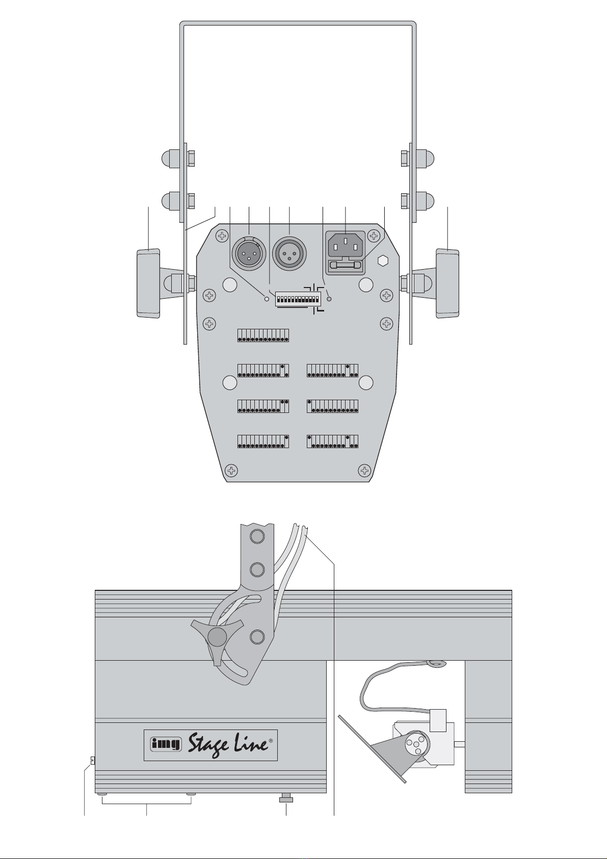
1Eléments et branchements
1Ecrous de blocage pour l’étrier de montage (2)
2Etrier de montage
3LED verte de contrôle :
a) si le signal de commande DMX est présent,
elle brille en continu.
b) en cas de contrôle par le programme interne,
elle clignote à chaque palier du programme.
c) en cas de gestion par la musique, elle cli-
gnote selon le rythme de la musique.
4Entrée signal DMX (XLR 3 pôles) :
1 = masse, 2 = DMX
-
, 3 = DMX+
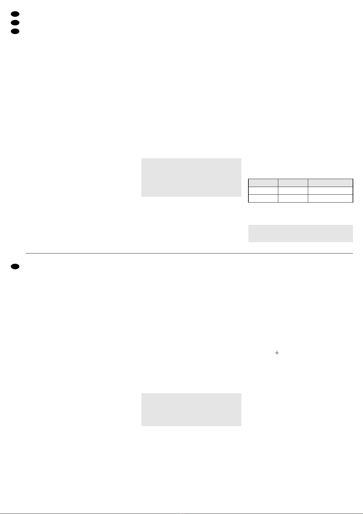
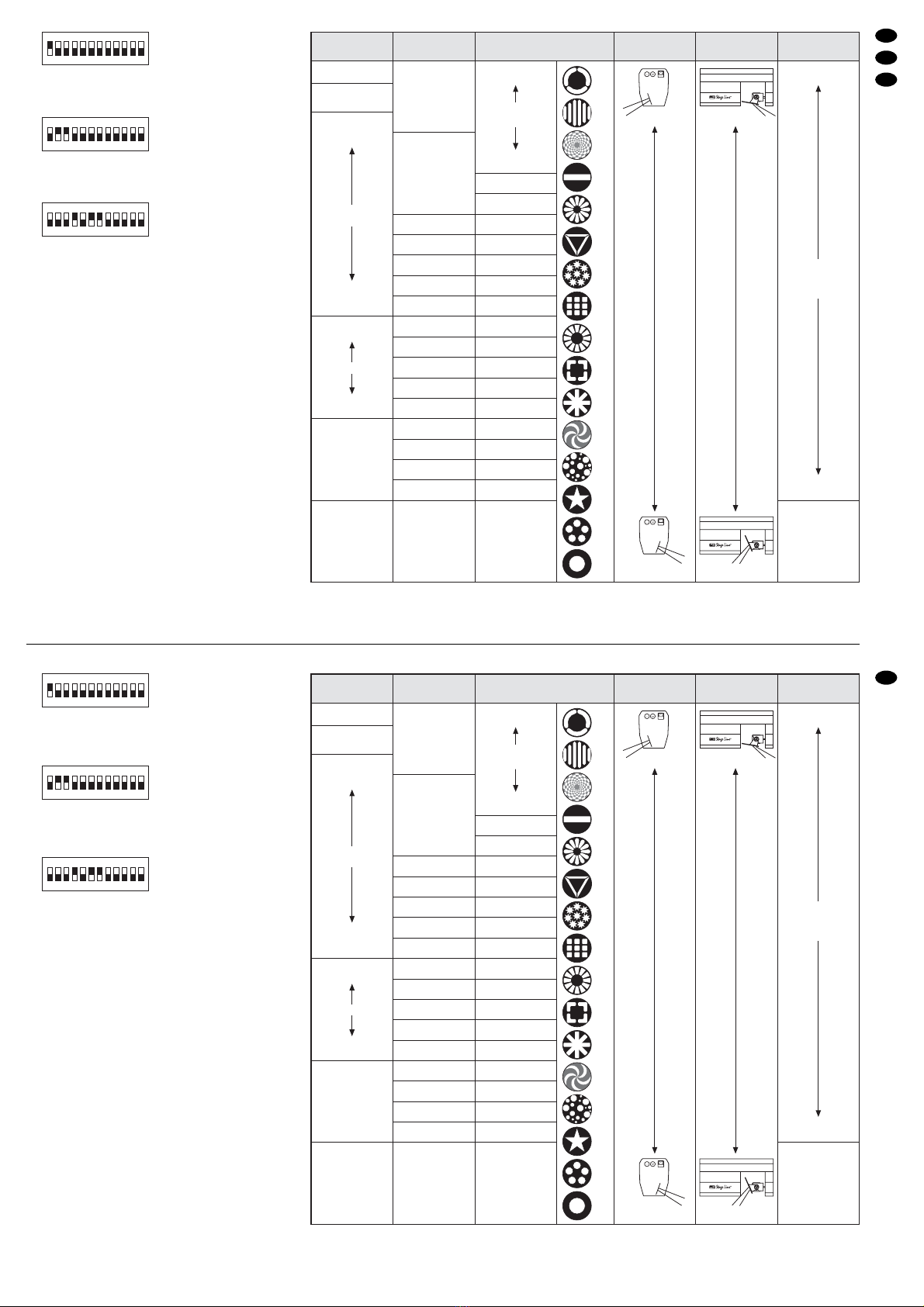
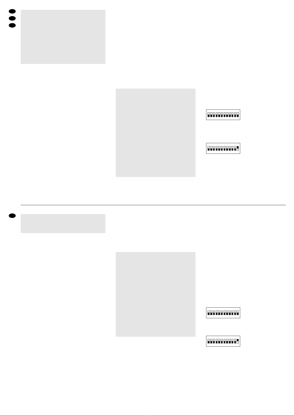
5Interrupteurs DIP N° 1–9 pour régler l’adresse
de démarrage DMX (voir chapitre 6.4) ;
interrupteurs DIP N° 10–12 pour la sélection du
mode de fonctionnement si aucun signal DMX
n’est utilisé (voir chapitre 6.1–6.3)
6Sortie signal DMX (XLR 3 pôles) :
1 = masse, 2 = DMX
-
, 3 = DMX+
7Témoin de fonctionnement POWER
8Prise secteur à brancher à une prise secteur
230V~/50Hz, via le cordon de liaison livré
9Porte fusible :
tout fusible fondu doit être remplacé uniquement
par un fusible de même type
10 Vis de réglage pour le positionnement de la
lampe à décharge
11 Vis du couvercle du compartiment lampe
12 Vis de blocage pour le réglage du focus, voir
chapitre 6.5
13 Corde de sécurité, non livrée :
indispensable pour assurer l’appareil s’il est
installé en hauteur au-dessus de personnes.
2Conseils d’utilisation et de sécurité
Cet appareil répond à la norme européenne
89/336/CEE relative à la compatibilité électroma-
gnétique et à la norme européenne 73/23/CEE por-
tant sur les appareils à basse tension.
Respectez scrupuleusement les points suivants :
●Cet appareil n’est conçu que pour une utilisation
en intérieur. Protégez-le de tout type de projec-
tions d’eau, des éclaboussures, d’une humidité
élevée et de la chaleur (plage de température de
fonctionnement autorisée : 0–40°C).
●Pendant le fonctionnement, l’appareil chauffe de
manière très importante. Pour éviter toute brûlure,
ne touchez jamais le boîtier pendant le fonc-
tionnement ; après avoir éteint l’appareil, laissez-
le refroidir 15 minutes avant de le toucher.
●Ne faites rien tomber dans les ouïes de ventila-
tion, vous pourriez vous électrocuter.
●Ne faites pas fonctionner l’appareil ou débran-
chez-le immédiatement du secteur lorsque :
1. des dommages apparaissent sur l’appareil, par
exemple le boîtier, la lentille ou sur le cordon
secteur,
2. après une chute ou un cas similaire, vous avez
un doute sur l’état de l’appareil,
3. des dysfonctionnement apparaissent.
●Ne débranchez jamais l’appareil en tirant sur le
cordon secteur ; retirez toujours le cordon secteur
en tirant la fiche.
●Pour nettoyer le boîtier, utilisez un chiffon sec et
doux, en aucun cas, de produits chimiques ou
d’eau. Pour la lentille et le miroir, vous pouvez uti-
liser des nettoyants pour verres usuels.
●Nous déclinons toute responsabilité en cas de
dommages matériels ou corporels résultants si
l’appareil est utilisé dans un but autre que celui
pour lequel il a été conçu, s’il n’est pas correcte-
ment monté, utilisé ou n’est pas réparé par une
personne habilitée, en outre, la garantie devien-
drait caduque.
●Lorsque l’appareil est définitivement retiré du ser-
vice, vous devez le déposer dans une usine de
recyclage adaptée pour contribuer à son élimina-
tion non polluante.
3Possibilités d’utilisation
Le scanner SCAN-150 est adapté à un utilisation
professionnelle sur scène ou en discothèque. Il pro-
jète des gobos de couleurs variés et permet ainsi de
créer une atmosphère “dance”. La gestion de la
lumière se fait par un programme interne, via le
microphone intégré ou via un contrôleur DMX.
4Placement de la lampe
Le jeu de lumière est livré sans lampe. Il convient
d’utiliser une lampe à décharge de type HTI 150W
avec un culot GY9,5.
En aucun cas, vous ne devez utiliser une lampe
de type différent !
Dans la gamme “img Stage Line”, les lampes sui-
vantes peuvent être utilisées :
Ne touchez jamais le bulbe de la lampe avec les
doigts ; la sueur et les pellicules grasses sur les
doigts diminuent la puissance lumineuse de la
lampe et se consument.
Attention !
L’appareil est alimenté par une tension dange-
reuse 230V~. Ne touchez jamais l’intérieur de
l’appareil car en cas de mauvaise manipulation,
vous pourriez subir une décharge électrique.
Faites toujours appel à un technicien spécialisé
pour effectuer les réparations.
Vi preghiamo di aprire completamente la pagina 3.
Così vedrete sempre gli elementi di comando e i
collegamenti descritti.
1Elementi di comando e collegamenti
1Dadi di bloccaggio per la staffa di montaggio (2)
2Staffa di montaggio
3LED verde di controllo:
a) Se è presente un segnale DMX di comando
rimane acceso.
b) Nel caso di comando attraverso il programma
interno lampeggia con ogni passo del pro-
gramma.
c) Nel caso di comando tramite la musica lam-
peggia nel ritmo della musica.
4Ingresso segnale DMX (XLR a 3 poli);
1 = massa, 2 = DMX
-
, 3 = DMX+
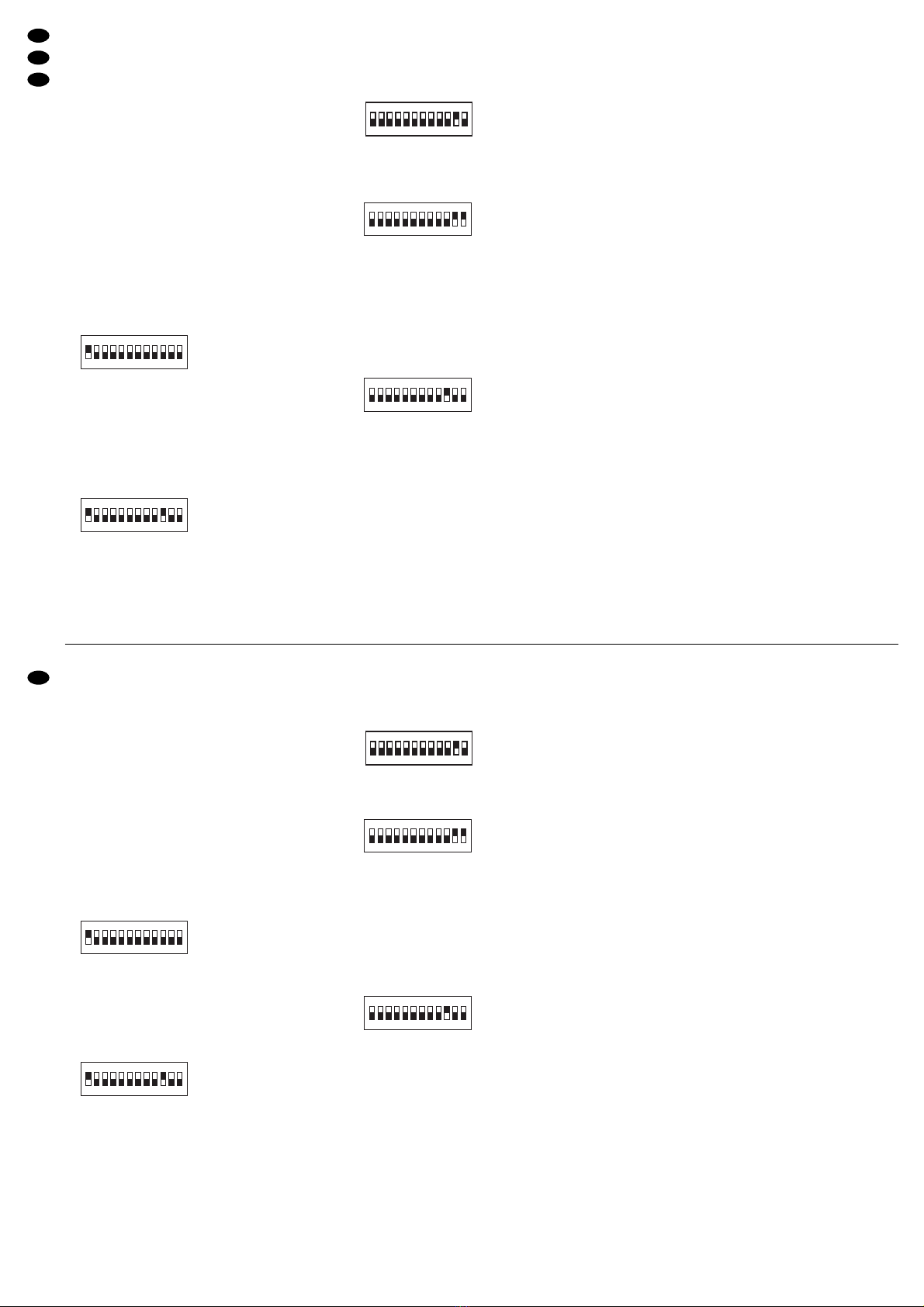
5DIP-switch n. 1–9 per impostare l’indirizzo DMX
di start (vedi capitolo 6.4);
DIP-switch n. 10–12 per selezionare la modalità
di funzionamento quando non viene usato nes-
sun apparecchio di comando DMX (vedi capitolo
6.1–6.3)
6Uscita segnale DMX (XLR a 3 poli);
1 = massa, 2 = DMX
-
, 3 = DMX+
7Spia di funzionamento POWER
8Presa per il collegamento ad una presa di rete
(230V~/50Hz) tramite l’apposito cavo in dota-
zione
9Portafusibile
Sostituire un fusibile difettoso solo con uno dello
stesso tipo.
10 Vite di regolazione per la posizione della lam-
pada a scarica elettrica
11 Viti per il coperchio del vano lampada
12 Vite di bloccaggio per la regolazione della messa
a fuoco, vedi capitolo 6.5
13 Fune di sicurezza, non in dotazione; è richiesta
in caso di sistemazione sospesa dell’appa-
recchio sopra delle persone
2Avvertenze di sicurezza
Quest’apparecchio è conforme alle direttive CE
89/336/CEE sulla compatibilità elettromagnetica e
73/23/CEE per apparecchi a bassa tensione.
Durante l’uso si devono osservare assolutamente i
seguenti punti:
●Far funzionare l’apparecchio solo all’interno di loca-
li. Proteggerlo dall’acqua gocciolante e dagli spruz-
zi d’acqua, da alta umidità dell’aria e dal calore
(temperatura d’impiego ammessa fra 0 e 40°C).
●Durante il funzionamento, l’apparecchio si riscal-
da molto. Per evitare ustioni non toccare il con-
tenitore durante il funzionamento, e dopo lo spe-
gnimento lasciarlo raffreddarsi per 15 minuti prima
di toccarlo.
●Non inserire oggetti nelle fessure d’aerazione.Altri-
menti si potrebbe provocare una scarica elettrica!
●Non mettere in funzione l’apparecchio e staccare
subito la spina rete se:
1. l’apparecchio, p.es. il contenitore, la lente, o il
cavo rete presentano dei danni visibili;
2. dopo una caduta o dopo eventi simili sussiste il
sospetto di un difetto;
3. l’apparecchio non funziona correttamente.
●Staccare il cavo rete afferrando la spina, senza ti-
rare il cavo.
●Per la pulizia usare solo un panno morbido,
asciutto; non impiegare in nessun caso prodotti
chimici o acqua. Per la lente e lo specchio si può
usare anche un detergente per vetri che si trova in
commercio.
●Nel caso d’uso improprio, di montaggio sbagliato,
d’impiego scorretto o di riparazione non a regola
d’arte non si assume nessuna garanzia per l’ap-
parecchio e nessuna responsabilità per eventuali
danni consequenziali a persone o a cose.
●Se si desidera eliminare l’apparecchio definitiva-
mente, consegnarlo per lo smaltimento ad un’isti-
tuzione locale per il riciclaggio.
3 Possibilità d’impiego
L’unità per effetti luce SCAN-150 è adatta in modo
particolare per l’impiego sul palcoscenico e in disco-
teca. L’apparecchio proietta diversi disegni colorati
creando un’atmosfera dancefloor ideale. Il comando
è possibile tramite un programma integrato, il micro-
fono integrato oppure per mezzo di un’unità di co-
mando luce DMX.
4Inserire la lampadina
L’unità viene consegnata senza lampadina. È richie-
sta una lampada a scarica elettrica del tipo HTI
150W con zoccolo GY9,5.
In nessun caso si devono usare lampadine di un
altro tipo!
Dal programma “img Stage Line” si possono usare
le seguenti lampadine:
Non toccare mai il vetro della lampadina con le dita!
I grassi e il sudore della pelle riducono la potenza e
lasciano tracce sul vetro.
Attenzione!
1. Staccare assolutamente la spina di rete prima di
inserire o togliere la lampada!
2. Poiché la lampada si riscalda moltissimo
durante il funzionamento, occorre che il conteni-
tore e la lampadina si possano raffreddare dopo
l’uso (minimo 15 minuti), prima di sostituire la
lampadina.
Attenzione!
Quest’apparecchio funziona con tensione di rete
di 230V~. Non intervenire mai al suo interno; la
manipolazione scorretta può provocare delle
scariche pericolose. Se l’apparecchio viene
aperto, cessa ogni diritto di garanzia. Per l’assi-
stenza, rivolgersi ad un laboratorio qualificato.
9
I
F
B
CH
Article Ref.Num. durée de vie moyenne
HLO-150HTI 05.0003 750h
HLO-152HTI 05.0007 2000h
Articolo N. d’ordine Durata media
HLO-150HTI 05.0003 750h
HLO-152HTI 05.0007 2000h

1) Dévissez les deux vis (11) du couvercle du com-
partiment lampe et retirez le couvercle.
2) La douille de la lampe est fixée sur une glissière.
Retournez la glissière si besoin en tournant la vis
de réglage (10).
3) Pour remplacer la lampe, retirez l’ancienne de la
douille.
4) Saisissez la nouvelle lampe par le côté en la te-
nant par le culot et placez-la dans la douille, de
sorte que le pin de connexion le plus gros se
place dans le trou de contact le plus grand.
5) Déplacez la glissière vers le réflecteur avec la vis
de réglage (10) jusqu’à ce que le bulbe de la
lampe disparaisse dans le réflecteur et que le culot
de verre se trouve encore devant le réflecteur.
Revissez le couvercle du compartiment lampe.
6) Une fois l’appareil allumé, réglez un faisceau
blanc sur la luminosité la plus grande et un éclai-
rage uniforme à l’aide de la vis de réglage.
●Les lampes proposées contiennent en faible
quantité des produits toxiques nocifs pour l’envi-
ronnement (mercure p.ex.). En Europe, il est im-
pératif de les déposer dans une poubelle adé-
quate pour déchets spéciaux. Dans d’autres pays,
vous devez vous reporter aux lois en vigueur.
●Il convient de remplacer la lampe au plus tard
après 1,25 fois sa durée de vie moyenne car une
durée d’utilisation croissante augmente de ma-
nière significative le risque d’un éclatement de la
lampe à la suite de modifications de structure du
verre quartz.
●Après un éclatement de la lampe pendant le fonc-
tionnement, il est recommandé de quitter l’envi-
ronnement immédiat de la lampe, par précaution,
pour éviter toute mise en danger de la santé gé-
nérée par des vapeurs de mercure dégagées ;
veillez à une aération correcte de la pièce.
5Montage
L’appareil doit être monté de manière appropriée et
sûre.
1) A l’aide d’un support de projecteur ou d’une vis
de montage stable, via l’étrier de montage (2),
fixez l’appareil à l’endroit souhaité (p.ex., tra-
verse d’un pied de lumière ou barre transversale)
2) Pour orienter l’appareil sur l’étrier de montage,
desserrez les deux écrous de blocage (1). Incli-
nez le scanner comme souhaité puis resserrez
les écrous.
6Utilisation
Reliez le cordon secteur à la prise secteur (8) puis
l’autre extrémité à une prise secteur 230V~/50Hz.
La LED POWER (7) brille et l’appareil est alors
allumé. Le miroir est placé dans une position de
départ définie et la commande est réinitialisée. L’ap-
pareil est ensuite prêt à fonctionner. Pour éteindre
l’appareil, débranchez le cordon secteur.
Pour un meilleur confort d’utilisation, il est recom-
mandé de relier l’appareil à une prise secteur pou-
vant être allumée et éteinte via un interrupteur.
Conseil : comme source de lumière, on utilise une
lampe à décharge. Si l’alimentation est interrompue,
même brièvement, la lampe ne s’allume pas tout de
suite. Elle doit refroidir quelques instants pour pou-
voir s’allumer à nouveau.
6.1 Gestion via la musique
1) Pour commander le SCAN-150 via le micro-
phone intégré, mettez les 12 interrupteurs DIP (5)
vers le bas sur la position d’arrêt.
Schema 3 gestion rapide via le micro
2) Avec l’interrupteur DIP numéro 12, on peut com-
muter entre gestion rapide ou lente via la musi-
que.
Schema 4 gestion lente via le micro
3) Réglez le système audio sur le volume corres-
pondant pour que la dynamique de la musique
soit restituée de manière optimale par les mou-
vements du faisceau lumineux et par les change-
ments des gobos et des couleurs.
La LED verte TRIG/DMX (3) brille brièvement
lorsque l’appareil modifie la couleur, le gobo ou
l’angle du faisceau via un signal musical.
121110987654321
ON
121110987654321
ON
Important !
1. Pour éviter toute accumulation de chaleur
dans l’appareil, le lieu de montage doit être
choisi de telle sorte que pendant le fonc-
tionnement, la circulation d’air est suffisante.
L’appareil doit être placé à une distance mini-
male de 1m des surfaces voisines et les
ouïes de ventilation sur le boîtier ne doivent
en aucun cas être obturées.
2. Veillez impérativement à laisser une distance
suffisante avec des matériaux facilement
inflammables ou sensibles à la chaleur.
3. Si l’appareil doit être suspendu au-dessus de
personnes, il doit être assuré (p.ex. avec
une corde de sécurité). Comme montré p.ex.
sur le schéma 2, une corde de sécurité (13)
peut être positionnée entre l’étrier de mon-
tage et le boîtier. Fixez la corde de telle sorte
que la distance de chute de l’appareil ne
puisse pas être supérieure à 20cm.
Attention !
1. Avant d’insérer ou retirer la lampe, vous devez
impérativement débrancher l’appareil du secteur.
2. Pendant le fonctionnement, la lampe est très
chaude, vous devez laisser refroidir le boîtier et
la lampe après toute utilisation et avant tout
remplacement (refroidissement pendant 15 mi-
nutes au moins).
3. Ne regardez jamais directement, appareil ou-
vert, vers la lampe à décharge allumée. La lumi-
nosité élevée et le rayonnement UV peuvent
engendrer des troubles de la vue.
1) Svitare le due viti (11) del vano lampada e
togliere il coperchio.
2) Il portalampada è fissato su una slitta. Se neces-
sario arretrare la slitta girando la vite di regola-
zione (10).
3) Per sostituire la lampadina sfilare quella vecchia
dal portalampada.
4) Afferrare la nuova lampadina lateralmente, allo
zoccolo e inserirla nel portalampada. Inserire il
contatto più grosso nel foro maggiore.
5) Con la vite di regolazione (10) spostare la slitta
verso il riflettore in modo che il bulbo di vetro
della lampadina scompaia nel riflettore mentre lo
zoccolo rimanga ancora davanti al riflettore. Ri-
avvitare il coperchio del vano lampada.
6) Dopo la messa in funzione e servendosi della vite
di regolazione regolare un raggio di luce bianca
in modo da aver il massimo di luminosità e un’il-
luminazione uniforme.
●Le lampadine indicate qui contengono piccole
quantità di sostanze nocive all’ambiente (p.es.
mercurio), e perciò in Europa devono essere trat-
tate come rifiuto tossico. In altri paesi si devono
rispettare le norme nazionali.
●Al massimo dopo 1,25 volte la durata media della
lampadina occorre sostituirla perché con l’uso
aumenta il rischio di scoppio in seguito alle modi-
fiche strutturali del vetro di quarzo.
●Se la lampadina scoppia durante l’uso conviene
abbandonare per precauzione le dirette vici-
nanze della lampadina per escludere completa-
mente i rischi alla salute per i vapori di mercurio
che si libereranno; provvedere ad una buona
aerazione dell’ambiente.
5Montaggio
L’apparecchio deve essere montato a regola d’arte
e in modo sicuro.
1) Fissare l’apparecchio con un supporto per lam-
pade spot o con una robusta vite di montaggio in
un punto adatto (per esempio ad una traversa o
al braccio di uno stativo per lampade), serven-
dosi della staffa di montaggio (2).
2) Per orientare l’apparecchio, allentare i due dadi
di bloccaggio (1) sulla staffa di montaggio. Incli-
nare l’apparecchio secondo necessità e stringere
bene i due dadi.
6Funzionamento
Collegare il cavo rete in dotazione con la presa (8)
ed inserire la spina in una presa di rete (230V~/
50Hz). Si accende la spia POWER (7) e l’appa-
recchio è acceso. Lo specchio si mette in una pre-
cisa posizione di partenza e il comando viene reset-
tato. Dopodiché l’unità è pronta. Per spegnerla
staccare la spina dalla rete.
Per maggiore comodità conviene collegare l’u-
nità con una presa comandata da un interruttore.
N.B.: Come sorgente di luce viene usata una lam-
pada a scarica elettrica. Se la corrente viene inter-
rotta solo brevemente, la lampada non si riaccende
subito. Deve prima raffreddarsi per potersi accen-
dere di nuovo.
6.1 Comando tramite la musica
1) Per comandare lo SCAN-150 tramite il microfono
integrato, portare tutti i 12 i dip-switch (5) in posi-
zione inferiore, spenta.
Fig. 3 Comando veloce tramite il microfono
2) Con il dip-switch n. 12 si può passare fra coman-
do veloce e comando lento della musica.
Fig. 4 Comando lento tramite il microfono
3) Impostare il volume dell’impianto di musica in
modo tale che il ritmo della musica venga ripro-
dotto in modo ottimale dai movimenti del raggio
di luce nonché dal cambio dei disegni e dei colori.
Il LED verde TRIG/DMX (3) si accende breve-
mente se l’apparecchio, in seguito ad un segnale
della musica, cambia colore, disegno o angolo
del raggio di luce.
121110987654321
ON
121110987654321
ON
Importante!
1. Per evitare un accumulo di calore nell’unità
stessa, il punto di montaggio deve essere
scelto in modo da garantire una circolazione
d’aria sufficiente. Lo strumento deve essere
ad una distanza minima di 1m dalle superfici
vicine, e le aperture di aerazione non devono
essere coperte in nessun caso.
2. Considerare anche una distanza di sicurezza
da materiali facilmente infiammabili o sensi-
bili al calore.
3. Se lo scanner viene installato sospeso,
sopra delle persone, deve essere assicurato
in modo particolare (p.es. con una fune di
sicurezza). Come illustrato in fig. 2, una fune
di sicurezza (13) va fatta passare fra la staffa
di montaggio e il contenitore. Fissare la fune
in modo tale che la caduta dell’apparecchio
non può superare i 20cm.
3. Non guardare mai direttamente la lampadina
accesa quando l’apparecchio è aperto. L’alta
luminosità e i raggi UV possono danneggiare gli
occhi.
10
I
F
B
CH

6.1.1 Fonctionnement combiné de plusieurs
SCAN-150
Il est possible de faire fonctionner en combinaison
jusqu’à 16 scanners pour commander d’autres
appareils auxiliaires (Slave) sur le même rythme, via
le micro de l’appareil principal (Master).
1) Reliez la prise de sortie (6) de l’appareil principal
via un cordon XLR 3 pôles (par exemple MEC-…
ou MECN-… de la gamme “img Stage Line”) à la
prise d’entrée (4) du premier appareil auxiliaire.
2) Reliez la prise de sortie du premier appareil auxi-
liaire à la prise d’entrée du deuxième appareil
auxiliaire et ainsi de suite jusqu’à ce que tous les
appareils soient reliés dans une seule et même
chaîne.
3) Sur l’appareil principal, mettez tous les interrup-
teurs DIP (5) sur la position inférieure ; pour une
gestion lente via la musique, mettez l’interrupteur
DIP numéro 12 vers le haut sur la position ON
(voir chapitre 6.1).
4) Sur les appareils auxiliaires, ne mettez que l’inter-
rupteur DIP numéro 1 sur la position supérieure
ON.
Schéma 5 mode slave
5) Dès que les signaux de commande de l’appareil
principal sont présents sur les appareils auxiliai-
res, la LED verte TRIG/MIX (3) sur ces appareils
brille. Sur les appareils auxiliaires dont les mou-
vements de rotation du miroir (Pan) doivent être
exactement opposés à l’appareil principal, mettez
l’interrupteur DIP numéro 10 sur la position ON.
Schéma 6 mode slave, rotation du miroir opposé à
l’appareil principal
6.2 Gestion via un programme interne
1) Si la gestion du SCAN-150 ne doit pas s’effectuer
via le micro mais via un programme interne, met-
tez uniquement l’interrupteur DIP numéro 11 sur
la position ON.
Schéma 7 gestion via un programme interne
2) Avec l’interrupteur DIP numéro 12, vous pouvez
commuter entre un déroulement rapide ou lent
du programme.
Schéma 8 déroulement lent du programme
3) Comme dans le cas de la gestion via la musique,
on peut également faire fonctionner en combinai-
son plusieurs appareils via une gestion par pro-
gramme interne pour obtenir des mouvements
synchronisés. Voir chapitre 6.1.1.
6.3 Mode test
Pour pouvoir effectuer un programme de test, met-
tez uniquement l’interrupteur DIP numéro 10 sur la
position ON.
Schéma 9 mode test
6.4 Utilisation via un contrôleur
Le SCAN-150 dispose de 6 canaux DMX pour être
utilisé via un contrôleur. Le tableau 13 sur la page
suivante présente les fonctions et valeurs DMX cor-
respondantes.
1) Reliez l’entrée DMX (4) à la sortie DMX du jeu de
lumière.
Pour le branchement, des câbles spécifiques
pour des flots importants de données doivent
être utilisés. L’emploi de câbles micro usuels ne
peut être recommandé que pour des longueurs
de câble de 100m maximum. Les meilleurs ré-
sultats de transmission sont obtenus avec un
câble micro blindé de section 2 x 0,25mm2ou
avec un câble spécifique pour la transmission de
données. Pour des longueurs de liaison à partir
de 150m, il est recommandé de brancher un am-
plificateur DMX de signal (p.ex. SR-103DMX de
“img Stage Line”).
2) Reliez la sortie DMX (6) à l’entrée DMX du jeu de
lumière suivant. Reliez sa sortie à l’entrée du pro-
chain appareil et ainsi de suite jusqu’à ce que
tous les jeux de lumière soient reliés dans une
chaîne.
3) Terminez la sortie DMX du dernier jeu de lumière
de la chaîne avec une résistance 120Ω(0,25W) :
soudez aux pins 2 et 3 d’une fiche XLR la résis-
tance et branchez la fiche dans la sortie DMX.
4) Pour pouvoir utiliser le SCAN-150 depuis un con-
trôleur, l’adresse de démarrage DMX pour le
canal DMX 1 doit être réglée via les interrupteurs
DIP (5). Si p.ex. sur le contrôleur, l’adresse 17
est prévue pour gérer le diaphragme, réglez sur
le SCAN-150 l’adresse de démarrage 17.
L’adresse de démarrage s’obtient en addi-
tionnant les valeurs binaires (1, 2, 4, …, 128,
256, voir schéma 10–12) des interrupteurs DIP
réglés sur la position ON, par exemple :
121110987654321
ON
121110987654321
ON
121110987654321
ON
121110987654321
ON
121110987654321
ON
6.1.1 Collegamento di più SCAN-150
Si possono collegare fino a 16 apparecchi per
comandare, per mezzo del microfono dell’appa-
recchio principale (Master), tutte le unità secondarie
(Slave) nello stesso ritmo.
1) Collegare l’uscita (6) dell’unità principale con l’in-
gresso (4) del primo apparecchio secondario ser-
vendosi di un cavo XLR a 3 poli (per esempio
della serie MEC-… o MECN-… del programma
“img Stage Line”).
2) Collegare l’uscita del primo apparecchio secon-
dario con l’ingresso del secondo apparecchio
secondario ecc., finché tutti gli apparecchi sono
collegati formando una catena.
3) Sull’apparecchio principale, portare tutti i dip-
switch (5) in posizione inferiore; per un comando
lento dalla musica, lo switch n. 12 deve essere in
alto, in posizione ON (cap. 6.1).
4) Sugli apparecchi secondari portare in alto, in
posizione ON, solo il dip-switch n. 1.
Fig. 5 Funzionamento Slave
5) Non appena agli apparecchi secondari sono pre-
senti i segnali di comando dell’unità principale, il
loro LED verde TRIG/DMX (3) rimane acceso.
Sugli apparecchi secondari, i cui movimenti di
rotazione dello specchio (pan) devono essere
opposti a quelli dell’apparecchio principale, por-
tare il dip-switch n. 10 in posizione ON.
Fig. 6 Funzionamento Slave, rotazione dello specchio
in senso opposto rispetto all’apparecchio princi-
pale
6.2 Comando tramite un programma interno
1) Se il comando dello SCAN-150 non deve essere
fatto attraverso il microfono, ma attraverso un
programma interno, portare in posizione ON solo
il dip-switch n. 11.
Fig. 7 Comando tramite un programma interno
2) Con il dip-switch n. 12 si può passare fra coman-
do veloce e comando lento dello svolgimento del
programma.
Fig. 8 Svolgimento lento del programma
3) Come nel comando tramite musica, nel caso del
comando tramite un programma interno si pos-
sono unire diversi apparecchi per avere dei movi-
menti sincronizzati. Vedere in merito cap. 6.1.1.
6.3 Funzionamento di prova
Per svolgere un programma di test, portare solo il
dip-switch n. 10 in posizione ON.
Fig. 9 Funzionamento di prova
6.4 Funzionamento tramite unità di comando
luce
Per il funzionamento tramite un’unità di comando
luce, lo SCAN-150 è equipaggiato con sei canali
DMX. La tabella fig. 13 alla pagina successiva indica
le funzioni e i rispettivi valori DMX.
1) Collegare l’ingresso DMX (4) con l’uscita DMX
dell’unità di comando luce.
Per il collegamento si dovrebbero usare cavi
per un alto flusso di dati. L’impiego di normali cavi
per microfoni è consigliabile solo per una lun-
ghezza complessiva dei cavi fino a 100m. I migli-
ori risultati di trasmissione si ottengono con cavi
schermati per microfoni di 2 x 0,25mm2oppure
con un cavo speciale per la trasmissione dati. Nel
caso di lunghezze oltre i 150m è consigliabile l’in-
serimento di un amplificatore (p.es. SR-103DMX
di “img Stage Line”).
2) Collegare l’uscita DMX (6) con l’ingresso DMX
della successiva unità per effetti luce, l’uscita di
quest’ultima con l’ingresso dell’unità successiva
e via dicendo finché tutte le unità sono collegate
formando una catena.
3) Terminare con una resistenza di 120Ω(0,25W)
l’uscita DMX dell’ultima unità per effetti luce della
catena: saldare la resistenza ai pin 2 e 3 di un
connettore XLR e inserire il connettore nell’uscita
DMX.
4) Per potere comandare lo SCAN-150 da un’unità
di comando luce, occorre impostare l’indirizzo di
start DMX per il primo canale DMX servendosi
dei dip-switch (5). Se, per esempio, per coman-
dare il diaframma, sull’unità di comando è previ-
sto l’indirizzo 17, bisogna impostare sullo SCAN-
150 l’indirizzo di start 17.
L’indirizzo di start risulta dall’addizione dei
valori binari (1, 2, 4 ... 128, 256, vedi fig. 10 – 12)
dei dip-switch portati in posizione ON, p.es.:
121110987654321
ON
121110987654321
ON
121110987654321
ON
121110987654321
ON
121110987654321
ON
11
I
F
B
CH

– Interrupteur DIP numéro
– Valeur binaire
Schéma 10 adresse de démarrage DMX 1
– Interrupteur DIP numéro
– Valeur binaire
Schéma 11 adresse de démarrage DMX 6 =
valeurs binaires 4 + 2
– Interrupteur DIP numéro
– Valeur binaire
Schéma 12 adresse de démarrage DMX 104 =
64 + 32 + 8
Le plus simple est toujours de partir de la valeur
binaire la plus grande possible et d’ajouter les
valeurs plus petites jusqu’à obtenir une somme
étant la valeur de l’adresse de démarrage.
Pour vous aider dans le réglage, il est possi-
ble de télécharger un gestionnaire d’adresses de
démarrage sur le site www.imgstageline.com,
SupportSoftware (Aide/Logiciel).
5) Après le réglage de l’adresse de démarrage pour
le canal 1, les canaux 2–6 sont attribués aux
adresses suivantes. Exemple :
Adresse de démarrage 17 : canal pour le dia-
phragme
Adresse 18 = canal pour la couleur
Adresse 19 = canal pour le gobo
Adresse 20 = canal pour la rotation du miroir
Adresse 21 = canal pour l’inclinaison du miroir
Adresse 22 = canal pour la vitesse
121110987654321
ON
1
2
4
8
16
32
64
128
256
121110987654321
ON
1
2
4
8
16
32
64
128
256
121110987654321
ON
1
2
4
8
16
32
64
128
256
– Dip-switch n.
– Valore binario
Fig. 10 Indirizzo di start DMX 1
– Dip-switch n.
– Valore binario
Fig. 11 Indirizzo di start DMX 6 = valori binari 4 + 2
– Dip-switch n.
– Valore binario
Fig. 12 Indirizzo di start DMX 104 = 64 + 32 + 8
Il sistema più semplice è quello di partire sempre
dal valore binario il più grande possibile aggiun-
gendo poi i valori minori fino al raggiungimento
dell’indirizzo di start.
Come aiuto per l’impostazione, dall’internet si
può scaricare un manager per gli indirizzi:
www.imgstageline.com, Support Software.
5) Dopo l’impostazione dell’indirizzo di start per il
1. canale, i canali 2–6 sono assegnati agli indi-
rizzi successivi. Esempio:
Indirizzo di start 17 = canale per il diaframma
Indirizzo 18 = canale per il colore
Indirizzo 19 = canale per il disegno (gobo)
Indirizzo 20 = canale per la rotazione dello
specchio
Indirizzo 21 = canale per l’inclinazione dello
specchio
Indirizzo 22 = canale per la velocità
In questo esempio, il prossimo indirizzo di start
possibile per il successivo apparecchio coman-
dato da DMX è l’indirizzo 23.
121110987654321
ON
1
2
4
8
16
32
64
128
256
121110987654321
ON
1
2
4
8
16
32
64
128
256
121110987654321
ON
1
2
4
8
16
32
64
128
256
12
I
F
B
CH
Canal 1
diaphragme Canal 2
couleur Canal 13
Gobo
Blackout
000–039
rapide
219
lent
180
000
255
lent
200
réinitialisation
254–255
fréquence
éclairs élevée
229
fréquence
éclairs faible
130
effet
stroboscope
000
255
blanc
000–039
rouge
040–049
diaphragme
ouvert
040–079
effet scintillement
lent
080
rapide
129
vert
050–059
jaune
060–069
bleu
070–079
orange
080–089
turquoise
090–099
magenta
100–109
bleu vert
110–119
jaune clair
120–129
cyan
130–139
rose
140–149
vert clair
150–159
rouge + bleu
160–169
4 couleurs
170–179
effet arc
en ciel
Blackout
230–253
rapide
255
lent
220
changement
continu
1
Gobo 1
040–049
Gobo 3
060–069
Gobo 2
050–069
Gobo 4
070–079
Gobo 5
080–089
Gobo 12
150–159
Gobo 11
140–149
Gobo 10
130–139
Gobo 6
090–099
Gobo 7
100–109
Gobo 8
110–119
Gobo 9
120–129
Gobo 13
160–169
Gobo 14
170–179
Gobo 15
180–189
Gobo 16
190–199
Canal 4
rotation (Pan)* Canal 5
inclinaison (Tilt) Canal 6
vitesse
changement
continu
rapide
255
aucun Gobo
000–039 2
3
4
5
6
7
8
9
10
11
12
13
14
15
16
vitesse
maximale
000–039
vitesse des
mouvements du
miroir
très lent
255
rapide
040
Schéma 13 configuration des canaux DMX
*l’orientation de la rotation du miroir peut être inversée avec l’interrupteur DIP numéro 10
Fig.13 Assegnazione dei canali DMX
* Con il dip-switch n. 10 è possibile invertire la rotazione dello specchio
Canale 1
Diaframma Canale 2
Colore Canale 3
Gobo
Blackout
000–039
veloce
219
lento
180
000
255
lento
200
Reset
254–255
alta frequenza
di lampi
229
bassa frequenza
di lampi
130
effetto
stroboscopio
000
255
bianco
000–039
rosso
040–049
diaframma aperto
040–079
effetto oscillante
lento
080
veloce
129
verde
050–059
giallo
060–069
blu
070–079
arancio
080–089
turchese
090–099
magenta
100–109
verde-blu
110–119
giallo chiaro
120–129
cyan
130–139
rosa
140–149
verde chiaro
150–159
rosso + blu
160–169
4 colori
170–179
effetto
arcobaleno
Blackout
230–253
veloce
255
lento
220
cambio
continuo
1
Gobo 1
040–049
Gobo 3
060–069
Gobo 2
050–069
Gobo 4
070–079
Gobo 5
080–089
Gobo 12
150–159
Gobo 11
140–149
Gobo 10
130–139
Gobo 6
090–099
Gobo 7
100–109
Gobo 8
110–119
Gobo 9
120–129
Gobo 13
160–169
Gobo 14
170–179
Gobo 15
180–189
Gobo 16
190–199
Canale 4
Rotazione (Pan)* Canale 5
Inclinazione (Tilt) Canale 6
Velocità
cambio
continuo
veloce
255
nessun Gobo
000–039 2
3
4
5
6
7
8
9
10
11
12
13
14
15
16
velocità
massima
000–039
velocità dei
movimenti dello
specchio
molto lento
255
veloce
040

Comme adresse de démarrage suivante possible
pour l’appareil à gestion DMX suivant, on peut utili-
ser, dans cet exemple, l’adresse 23.
6) Après le réglage de l’adresse de démarrage, le
SCAN-150 peut être utilisé via le contrôleur relié.
Dès que des signaux de commande sont reçus
du contrôleur DMX, la LED verte TRIG/DMX (3)
brille.
6.5 Réglage du focus
1) Pour le réglage du focus, desserrez un peu la vis
de blocage (12) [ne la dévissez pas].
2) En déplaçant la vis dans le long trou, réglez une
représentation précise des gobos. Le réglage de
la précision dépend de la distance de l’appareil
avec la surface de projection.
3) Revissez la vis.
7Nettoyage de l’optique
Il est recommandé de nettoyer régulièrement le
miroir et la lentille, des impuretés causées par la
poussière, la fumée ou toute autre particule. C’est à
cette seule condition que la lumière peut rayonner
avec une luminosité maximale. Avant l’ouverture de
l’appareil, débranchez-le du secteur et laissez-le
refroidir pendant 15 minutes.
Pour le nettoyage, utilisez un chiffon doux et pro-
pre et des produits de nettoyage de verres usuels ;
ensuite, essuyez avec précaution les éléments.
8Caractéristiques techniques
Alimentation : . . . . . . . . . . . . 230V~/50Hz
Consommation : . . . . . . . . . . 350VA
Lampe : . . . . . . . . . . . . . . . . 1 x lampe à
décharge,
type HTI 150W avec
culot GY9,5
Rotation miroir (Pan) : . . . . . 180° max.
Inclinaison miroir (Tilt) : . . . . 45° max.
Température fonc. : . . . . . . . 0–40°C
Dimensions : . . . . . . . . . . . . 240 x 190 x 380 mm
Poids : . . . . . . . . . . . . . . . . . 7,5kg
D’après les données du constructeur.
Tout droit de modification réservé.
6) Dopo l’impostazione dell’indirizzo start, lo SCAN-
150 può essere comandato tramite l’unità di
comando collegata. Non appena si ricevono dei
segnali di comando dall’unità DMX si accende il
LED verde TRIG/DMX (3).
6.5 Impostazione del fuoco
1) Per impostare la messa a fuoco, allentare legger-
mente la vite di bloccaggio (12) senza svitarla
completamente.
2) Spostando la vite di bloccaggio nella sua asola,
mettere a fuoco i disegno. Il fuoco dipende dalla
distanza fra apparecchio e superficie su sui si
proietta.
3) Stringere di nuovo la vite di bloccaggio.
7Pulizia del sistema ottico
Si dovrebbe procedere, ad intervalli regolari, alla
pulizia dello specchio e della lente per asportare pol-
vere, fumo e altre particelle. Solo così, la luce può
essere irradiata con la luminosità massima. Prima di
aprire l’apparecchio staccare la spina dalla presa di
rete e fare raffreddare l’apparecchio per 15 minuti
circa.
Per la pulizia usare un panno morbido, pulito e un
detergente per vetri come si trovano in commercio.
Quindi asciugare le parti delicatamente.
8Dati tecnici
Alimentazione: . . . . . . . . . . . 230V~/50Hz
Potenza assorbita: . . . . . . . . 350VA
Lampadina: . . . . . . . . . . . . . 1 x lampada a sca-
rica elettrica
tipo HTI 150W con
zoccolo GY9,5
Rotazione specchio (pan): . . max. 180°
Inclinazione specchio (tilt): . . max. 45°
Temperatura d’impiego: . . . . 0–40°C
Dimensioni: . . . . . . . . . . . . . 240 x 190 x 380mm
Peso: . . . . . . . . . . . . . . . . . . 7,5kg
Dati forniti dal costruttore.
Con riserva di modifiche tecniche.
13
I
F
B
CH
Notice d’utilisation protégée par le copyright de MONACOR®INTERNATIONAL GmbH & Co. KG. Toute
reproduction même partielle à des fins commerciales est interdite.
La MONACOR®INTERNATIONAL GmbH & Co. KG si riserva ogni diritto di elaborazione in qualsiasi forma
delle presenti istruzioni per l’uso. La riproduzione – anche parziale – per propri scopi commerciali è vietata.

Vouw bladzijde 3 helemaal open, zodat u steeds
een overzicht hebt van de bedieningselementen
en de aansluitingen.
1Overzicht van de bedieningselemen-
ten en aansluitingen
1Stelmoeren voor de montagebeugel (2)
2Montagebeugel
3Groene controle-LED:
a) Licht continu op bij ontvangen DMX-bestu-
ringssignaal
b) Bij de besturing door het interne programma
knippert de LED bij elke programmastap.
c) Bij de muzieksturing knippert de LED op het
ritme van de muziek.
4DMX-signaalingang (3-pol. XLR);
1 = massa, 2 = DMX
-
, 3 = DMX+
5DIP-schakelaars nr. 1–9 voor het instellen van
het DMX-startadres (zie hoofdstuk 6.4);
DIP-schakelaar nr. 10–12 voor het selecteren
van de bedrijfsmodus, wanneer u geen DMX-be-
sturingsapparaat gebruikt (zie hoofdstuk 6.1– 6.3)
6DMX-signaaluitgang (3-pol. XLR);
1 = massa, 2 = DMX
-
, 3 = DMX+
7POWER-LED
8POWER-jack voor aansluiting op een stop-
contact (230V~/50Hz) met behulp van het bij-
geleverde netsnoer
9Houder voor de netzekering
Vervang een gesmolten zekering uitsluitend door
een zekering van hetzelfde type.
10 Justeerschroef voor de positie van de ontla-
dingslamp
11 Schroeven voor het deksel van het lampencom-
partiment
12 Stelschroef voor de focusinstelling,
zie hoofdstuk 6.5
13 Hijskabel, niet in de levering inbegrepen;
noodzakelijk om het apparaat veilig vast te ma-
ken, wanneer het als zwevende last boven per-
sonen wordt geïnstalleerd
2Veiligheidsvoorschriften
Dit apparaat is in overeenstemming met de EU-
richtlijn 89/336/EEG voor elektromagnetische com-
patibiliteit en 73/23/EEG voor toestellen op laag-
spanning.
Let eveneens op het volgende:
●Het apparaat is enkel geschikt voor gebruik bin-
nenshuis. Vermijd druip- en spatwater, uitzonder-
lijk warme plaatsen en plaatsen met een hoge
vochtigheid (toegestaan omgevingstemperatuur-
bereik: 0–40°C).
●Het apparaat warmt tijdens het gebruik zeer sterk
op. Om brandwonden te voorkomen, raakt u de
behuizing niet aan tijdens het gebruik resp. laat u
het apparaat na uitschakelen 15 minuten af-
koelen, alvorens het vast te nemen.
●Zorg ervoor dat u niets in de ventilatieopeningen
steekt. Er bestaat immers gevaar voor elektrische
schokken!
●Schakel het apparaat niet in resp. trek onmiddel-
lijk de stekker uit het stopcontact:
1. het apparaat, b.v. aan de behuizing, de lens, of
het netsnoer zichtbaar is beschadigd,
2. er een defect zou kunnen optreden nadat het
apparaat bijvoorbeeld gevallen is,
3. het apparaat slecht functioneert.
●Trek de stekker nooit met het snoer uit het stop-
contact, maar met de stekker zelf.
●Verwijder het stof van de behuizing met een
droge, zachte doek. Gebruik zeker geen water of
chemicaliën. Voor de lens en de spiegel kunt u
ook in de handel verkrijgbare detergenten voor
glas gebruiken.
●In geval van ongeoorloofd of verkeerd gebruik,
verkeerde montage, foutieve bediening of van
herstelling door een niet-gekwalificeerd persoon
vervalt de garantie en de verantwoordelijkheid
voor hieruit resulterende materiële of lichamelijke
schade.
●Wanneer het apparaat definitief uit bedrijf wordt
genomen, bezorg het dan voor milieuvriendelijke
verwerking aan een plaatselijk recyclagebedrijf.
3Toepassingen
Het lichteffectapparaat SCAN-150 is in het bijzonder
geschikt voor gebruik op het podium en in discothe-
ken. Het projecteert diverse, veelkleurige patronen
en zorgt voor een ideale sfeer op de dansvloer. De
besturing van het apparaat kan gebeuren via een
intern programma, via de ingebouwde microfoon of
via een DMX-lichtregelaar.
4De lampen aanbrengen/vervangen
Het lichteffectapparaat wordt zonder lampen gele-
verd. Voor dit apparaat is een ontladingslamp van
het type HTI 150W met een voet GY9,5 nodig.
Er mogen in geen geval lampen van een ander
type worden gebruikt!
Uit het gamma “img Stage Line” kunnen volgende
lampen worden gebruikt:
Raak de glazen ballon van de nieuwe lamp niet met
de vingers aan! Huidvet en -zweet verminderen de
lichtsterkte en branden zich in.
Opgelet!
1. Alvorens de lamp aan te brengen resp. te ver-
wijderen, dient u in elk geval de stekker uit het
stopcontact te trekken!
Let op!
De netspanning (230V~) van het apparaat is
levensgevaarlijk. Open het apparaat niet, want
door onzorgvuldige ingrepen loopt u het risico
van elektrische schokken. Laat het apparaat in
een erkende werkplaats herstellen.
Abrir el presente libro página 3 de manera a
visualizar los elementos y las conexiones.
1Elementos y conexiones
1Tuercas de bloqueo para el soporte de montaje (2)
2Soporte de montaje
3LED verde de control:
a) si la señal de control DMX está presente,
brilla en continuo.
b) en caso de control por el programa interno,
parpadea a cada etapa del programa.
c) en caso de control mediante música, parpa-
dea según el ritmo de la música.
4Entrada señal DMX (XLR 3 polos);
1 = masa, 2 = DMX
-
, 3 = DMX+
5Interruptores DIP N° 1–9 para regular la direc-
ción de arranque DMX (vea capítulo 6.4):
interruptores DIP N° 10– 12 para la selección del
modo de funcionamiento si no se utiliza ningún
controlador DMX (vea capítulo 6.1–6.3)
6Salida señal DMX (XLR 3 polos);
1 = masa, 2 = DMX
-
, 3 = DMX+
7Testigo de funcionamiento POWER
8Toma de red para conectar a una toma de
230V~/50Hz, vía el cable de red entregado
9Porta fusible: todo fusible fundido debe cam-
biarse solamente por un fusible de mismo
10 Tuerca de reglaje para la posición de la lámpara
a descarga
11 Tuercas para la tapa del compartimiento de la
lámpara
12 Tuerca de bloqueo para el reglaje del enfoque,
vea capítulo 6.5
13 Cuerda de seguridad, no entregada: indispen-
sable para que el aparato se instale con seguri-
dad en altura encima de personas
2Consejos de utilizacion y seguridad
Este aparato cumple con la normativa europea
89/336/CEE relativa a la compatibilidad electroma-
gnética y con la normativa europea 73/23/CEE
relativa a los aparatos de baja tensión
Respectes escrupulosamente los puntos siguientes:
●Este aparato está fabricado únicamente para una
utilizacion en interior. No lo exponga a proyeccio-
nes de agua, a las salpicaduras, a una fuerte
humedad y al calor (rango de temperatura de fun-
cionamiento aconsejado: 0–40°C).
●Durante el funcionamiento, el aparato se calienta
mucho. Para evitar quemaduras, no manipule
nunca la carcasa durante el funcionamiento; deje
siempre enfriar el aparato 15 minutos antes de
cualquier manipulación.
●No inserte nada en los agujeros de ventilación,
podría sufrir una descarga eléctrica mortal.
●No deje funcionar el aparato y desconéctelo inme-
diatamente cuando:
1. aparecen daños en el aparato, por ejemplo la
carcasa, la lente o el cable de conexión.
2. después de una caída o caso similar, si tiene
cualquier duda sobre el estado del aparato.
3. mal funcionamiento aparece.
●No desconecte nunca el aparato tirando directa-
mente del cable de conexión, sujételo siempre por
la extremidad (toma).
●Para limpiar el aparato, utilice un paño seco y
suave, no utilice nunca productos químicos o
agua. Para la lente y el espejo, puede utilizar pro-
ductos de limpieza usuales para cristales.
●Rechazamos cualquier responsabilidad en caso
de daños materiales o corporales resultantes de
una utilizacion no adecuada del aparato, si no
está correctamente instalado, utilizado o reparado
por una persona habilitada y cualificada, además
por todos estos mismos motivos el aparato
carecería de todo tipo de garantía.
●Cuando el aparato está definitivamente sacado
del servicio, deposítelo en una fábrica de re-
ciclaje, para contribuir a una eliminación no conta-
minante.
3Posibilidades de utilización
El escáner SCAN-150 se adapta especialmente a
una utilización profesional en escenario o en disco-
teca. Proyecta gobos y colores diversos y permite
crear un ambiente ideal “dance”. El control de la luz
se efectúa mediante un programa interno, via el
micro integrado o via un controlador DMX.
4Instalación de la lámpara
El efecto de luz está entregado sin lámpara. Es
necesario utilizar una lámpara a descarga de tipo
HTI 150W con un zócalo tipo GY9,5.
¡No utilice nunca una lámpara de tipo diferente!
En la gama “img Stage Line”, puede utilizar las lám-
paras siguientes:
No manipule nunca el cristal de la lámpara con los
dedos; el sudor y las partículas de grasa de los
dedos disminuyen la potencia luminosa de la lám-
para y se marcan.
¡Atención!
El aparato está alimentado por una tensión peli-
grosa de 230V~. No manipule nunca el interior
del aparato, en caso de manipulación inade-
cuada, podría sufrir una descarga eléctrica mor-
tal. Acuda siempre a un técnico especializado y
cualificado para efectuar las reparaciones.
14
E
NL
B
Artikel bestelnr. gemiddelde levensduur
HLO-150HTI 05.0003 750h
HLO-152HTI 05.0007 2000h
Article Ref. num. Duración de vida media
HLO-150HTI 05.0003 750h
HLO-152HTI 05.0007 2000h

1) Draai de twee schroeven (11) van het deksel van
het lampencompartiment los en verwijder het
deksel.
2) De lampfitting is op een slede bevestigd. Indien
nodig plaatst u de slede terug door aan de
justeerschroef (10) te draaien.
3) Bij het vervangen van de lamp trekt u de oude
lamp uit de fitting.
4) Neem de nieuwe lamp opzij aan de voet vast en
steek ze in de fitting. Steek de dikkere aansluit-
pen hierbij in het grotere contactgat.
5) Beweeg de slede met de justeerschroef (10) zo
ver terug naar de reflector, dat de glazen ballon
van de lamp in de reflector verdwijnt en de glazen
voet zich nog vóór de reflector bevindt. Schroef
het deksel van het lampencompartiment opnieuw
vast.
6) Na de ingebruikneming stelt u met de justeer-
schroef een witte lichtbundel in op maximale hel-
derheid en gelijkmatige verlichting.
●De hier beschreven lampen bevatten geringe
hoeveelheden stoffen die schadelijk zijn voor het
leefmilieu (b.v. kwikzilver) en moeten daarom in
Europa als speciaal afval worden verwijderd. In
de andere landen dient men zich te houden aan
de desbetreffende nationale voorschriften.
●De lamp moet uiterlijk na de 1,25-voudige gemid-
delde levensduur worden vervangen, aangezien
bij langer gebruik het risico op barsten sterk
toeneemt ten gevolge van structurele veranderin-
gen in het kwartsglas.
●Wanneer de lamp barst op het ogenblik dat het
toestel is ingeschakeld, ontruimt men best uit
voorzorg de onmiddellijke omgeving van de lamp
om gevaar voor de gezondheid door vrijkomende
kwikzilverdampen volledig uit te sluiten; zorg
daarbij voor een goede ventilatie van de ruimte.
5Montage
Het apparaat moet deskundig en veilig worden
gemonteerd.
1) Verbind het apparaat door middel van een spot-
lichthouder resp. een stabiele montageschroef
met de montagebeugel (2) op de gewenste
plaats (b.v. aan een traverse of aan de dwars-
stang van lichtbundelapparatuur).
2) Om het apparaat te richten, draait u de twee stel-
moeren (1) op de montagebeugel los. Stel de
gewenste hellingshoek van het apparaat in en
draai de moeren weer vast.
6Bediening
Sluit het bijgeleverde netsnoer aan op de POWER-
jack (8) en plug de stekker in een stopcontact
(230V~/50Hz). De POWER-LED (7) licht op en het
apparaat is ingeschakeld. De spiegel wordt in een
vastgelegde uitgangspositie gebracht en de bestu-
ring wordt gereset. Daarna is het apparaat gebruiks-
klaar. Trek de stekker uit het stopcontact om het
apparaat uit te schakelen.
Voor een makkelijker bediening is het aangera-
den het toestel in een stopcontact te pluggen dat u
via een lichtschakelaar kan in- en uitschakelen.
Opmerking: Een ontladingslamp dient als lichtbron.
Indien de voedingsspanning slechts kort wordt
onderbroken, licht de lamp niet onmiddellijk weer
op. Ze moet eerst even afkoelen, om opnieuw te
kunnen doen branden.
6.1 Muzieksturing
1) Om de SCAN-150 via de ingebouwde microfoon
te sturen, plaatst u alle 12 DIP-schakelaars (5)
naar beneden in uitgeschakelde stand.
Fig. 3 snelle besturing via de microfoon
2) Met de DIP-schakelaar nr. 12 kunt u tussen
snelle en langzame muzieksturing wisselen.
Fig. 4 langzame besturing via de microfoon
3) Stel de muziekinstallatie op het betreffende
geluidsvolume in zodat de dynamiek van de
muziek optimaal wordt weergegeven door de
bewegingen van de lichtbundel en door het wis-
selen van de lichtpatronen en de kleuren.
De groene LED TRIG/DMX (3) licht kort op,
wanneer het apparaat door een muzieksignaal
de kleur, het patroon of de hoek van de lichtbun-
del verandert.
121110987654321
ON
121110987654321
ON
Belangrijk!
1. Om te vermijden dat het apparaat oververhit
geraakt, moet de installatieplaats zorgvuldig
worden geselecteerd, zodat tijdens het ge-
bruik voldoende ventilatie is gegarandeerd.
De afstand tussen het apparaat en de aan-
grenzende oppervlakken moet minstens 1m
bedragen, en de ventilatieopeningen van de
behuizing mogen in geen geval worden afge-
dekt.
2. Zorg in elk geval ook voor een voldoende
grote afstand tot licht ontvlambare of hittege-
voelige materialen.
3. Indien het apparaat als zwevende last boven
personen wordt geïnstalleerd, moet het bij-
komend worden beveiligd (b.v. door een hijs-
kabel). Een hijskabel kan bijvoorbeeld zoals
in figuur 2 tussen de montagebeugel en de
behuizing door worden geleid. Bevestig de
hijskabel zo dat het apparaat niet meer dan
20cm kan vallen.
2. Omdat de lamp tijdens het gebruik zeer heet
wordt, moeten de behuizing en de lamp na
gebruik van het apparaat eerst afkoelen (afkoel-
tijd min. 15 minuten), alvorens de lamp te ver-
vangen.
3. Kijk bij een geopend apparaat nooit rechts-
treeks in de brandende ontladingslamp. De
grote helderheid en de UV-straling kunnen be-
schadiging van de ogen veroorzaken.
1) Desatornille las dos tuercas (11) de la tapa del
compartimiento de la lámpara y saquée la tapa.
2) La portalámpara está fijada sobre una corredera.
Retorna la corredera si es necesario girando la
tuerca de reglaje (10).
3) Para cambiar la lámpara, saque la antigua del
portalámpara.
4) Sujete la lámpara por el lado del zócalo, coló-
quela en el portalámpara de manera a que el pin
de conexión más grande encaje en el agujero de
contacto más grande.
5) Desplace la corredera hacia el reflector con la
tuerca de reglaje (10) hasta que el cristal de la
lámpara desaparezca dentro del reflector pero el
zócalo de cristal se encuentra todavía antes el
reflector. Atornille la tapa del compartimiento de
lámpara.
6) Una vez el aparato conectado, regule el haz blan-
co sobre la luminosidad más grande y una ilumi-
nación uniforme mediante la tuerca de reglaje.
●Las lámparas indicadas contienen en baja canti-
dad productos tóxicos nocivos para el medio am-
biente (mercurio por ejemplo). En Europa, es im-
perativo depositarlas en basuras adecuadas es-
peciales. En otros países, vea las leyes vigentes.
●Debe cambiar la lámpara lo más tarde después
de pasar 1,25 veces el tiempo de la duración
media de vida. Una duración larga de utilización
aumenta de manera significativa el riesgo de una
explosión de la lámpara por las modificaciones
de estructura del cristal de cuarzo.
●En el caso de una explosión de la lámpara du-
rante el funcionamiento, le aconsejamos de salir
del entorno inmediato de la lámpara por precau-
ción para evitar cualquier peligro provocado por
la dispersión de vapores de mercurio; controle
que se efectué una buena aeración.
5Montaje
El aparato debe instalarse con seguridad de manera
profesional.
1) Con su soporte de montaje (2), fije el aparato en
el lugar deseado (por ejemplo, traversa de un pie
de luz o barra transversal) mediante un soporte
para proyectores o un tornillo de montaje estable.
2) Para orientar el aparato, desatornille las dos
tuercas de bloqueo (1) del soporte de montaje.
Incline el escáner como deseado y atornille de
nuevo las dos tuercas.
6Utilización
Conecte el cable de conexión entregado a una toma
de red (8) y la toma del cable a la red de 230V~/
50Hz. El LED POWER (7) brilla y el aparato está
conectado. El espejo se coloca en una posición de
arranque definida y el control se reinicializa. Enton-
ces el aparato está listo para funcionar. Para apagar
el aparato, desconecte el cable de conexión.
Para una mejor utilizacion, le aconsejamos
conectar el aparato a una toma de red que se pueda
conectar y desconectar mediante un interruptor.
Consejo: como fuente de luz, se utiliza una lámpara
a descarga. Si se interrumpe la alimentación, mismo
brevemente, la lámpara no enciende de seguida.
Debe enfriarse unos instantes para poder conectar
de nuevo.
6.1 Control mediante música
1) Para controlar el SCAN-150 mediante el micro
integrado, ponga todos los 12 interruptores DIP
(5) hacia bajo en la posición OFF.
Esquema 3 control rápido mediante el micro
2) Con el interruptor DIP número 12, puede conmu-
tar entre gestión rápida o lente via la música.
Esquema 4 control lento mediante el micro
3) Regule el sistema audio sobre el volumen cor-
respondiente para que la dinámica de la música
se restituya de manera óptimo por los movimien-
tos del haz luminoso y por el cambio de los
gobos y de los colores.
El LED verde TRIG/DMX (3) brilla breve-
mente cuando el aparato modifica el color, el
gobo o el ángulo del haz luminoso via una señal
musical.
121110987654321
ON
121110987654321
ON
¡Importante!
1. Para evitar toda acumulación de calor dentro
del aparato, debe elegir el lugar de montaje
de manera que durante el funcionamiento, la
circulación de aire sea suficiente. Debe colo-
car el aparato a una distancia mínima de 1m
de las superficies vecinas. Los agujeros de
ventilación de la carcasa no deben estar
obstruidos en ningún caso.
2. Deje imperativamente una distancia sufi-
ciente entre el aparato y los materiales fácil-
mente inflamables o sensibles al calor.
3. Si instala el aparato en suspensión encima
de personas, debe tener adicionalmente una
seguridad (por ejemplo una cuerda de segu-
ridad). Como explicado en el esquema 2,
puede colocar una cuerda de seguridad (13)
entre el soporte de montaje y la carcasa. Fije
la cuerda de manera a que la distancia de
caída del aparato no sea superior a 20cm.
¡Atención!
1. Antes de insertar o sacar la lámpara, debe impe-
rativamente desconectar el aparato de la red.
2. Durante el funcionamiento, la lámpara es muy
caliente, déje enfriar la carcasa y la lámpara
como mínimo 15 minutos después de cada uti-
lización y antes de efectuar cualquier cambio.
3. No mire nunca directamente, aparato abierto,
hacia la lámpara a descarga encendida. La
luminosidad elevada y los rayos UV pueden
provocar daños de vista.
15
E
NL
B

6.1.1 Meerdere SCAN-150-apparaten aaneen-
schakelen
U kunt maximaal 16 apparaten aaneenschakelen
om zo via de microfoon van het centrale apparaat
(master) alle overige randapparaten (slave) op het-
zelfde ritme te besturen.
1) Verbind de uitgangsjack (6) van het centrale
apparaat via een 3-polige XLR-kabel (b.v. serie
MEC-... of MECN-... uit het gamma van “img
Stage Line”) met de ingangsjack (4) van het eer-
ste randapparaat.
2) Verbind de uitgangsjack van het eerste randap-
paraat met de ingangsjack van het tweede rand-
apparaat etc. tot alle apparaten in een ketting
met elkaar zijn verbonden.
3) Plaats op het centrale apparaat alle DIP-schake-
laars (5) in de onderste stand; voor een lang-
zame muzieksturing echter schuift u de schake-
laar nr. 12 omhoog in de stand ON (hoofdstuk
6.1).
4) Op de randapparaten plaatst u alleen de DIP-
schakelaar nr. 1 omhoog in de stand ON.
Fig. 5 Slavebediening
5) Zodra de randapparaten de besturingssignalen
van het hoofdapparaat ontvangen, lichten de res-
pectieve groene LED’sTRIG / DMX op (3). Op de
randapparaten waarvan de spiegel-draaibewe-
gingen (Pan) precies omgekeerd ten opzichte
van het centrale apparaat moeten gebeuren,
plaatst u de DIP-schakelaar nr. 10 in de stand
ON.
Fig. 6 Slavebediening, spiegel-draaibeweging om-
gekeerd ten opzichte van het centrale
apparaat
6.2 Besturing door een intern programma
1) Indien de besturing van de SCAN-150 niet via de
microfoon zou gebeuren, maar door een intern
programma, plaats dan alleen de DIP-schakelaar
nr. 11 in de stand ON.
Fig. 7 Besturing door een intern programma
2) Met de DIP-schakelaar nr. 12 kunt u wisselen
tussen snelle en langzame programmaloop.
Fig. 8 Langzame programmaloop
3) Net zoals bij de muzieksturing kunt u ook bij de
interne programmabesturing meerdere appara-
ten aaneenschakelen om synchrone bewegingen
te genereren. Zie hiervoor hoofdstuk 6.1.1.
6.3 Testen
Om een testprogramma te runnen, stelt u alleen de
DIP-schakelaar nr. 10 in de stand ON.
Fig. 9 Testen
6.4 Bediening via een lichtregelaar
Voor de bediening via een lichtregelaar beschikt de
SCAN-150 over zes DMX-kanalen. In de tabel van
figuur 13 op de volgende pagina zijn de functies en
bijbehorende DMX-waarden vermeld.
1) Verbind de DMX-ingang (4) met de DMX-uitgang
van de lichtregelaar.
Voor de aansluiting moeten speciale kabels
voor hoge gegevensstromen worden gebruikt.
Wanneer gebruik wordt gemaakt van gewone
microfoonkabels, mag de totale kabellengte niet
meer dan 100m bedragen. De beste overdracht
wordt verkregen met een afgeschermde micro-
foonkabel van 2 x 0,25mm2of een speciale data-
transmissiekabel. Bij kabellengten vanaf 150m
wordt het tussenschakelen van een DMX-op-
haalversterker aanbevolen (b.v. SR-103DMX van
“img Stage Line”).
2) Verbind de DMX-uitgang (6) met de DMX-ingang
van de volgende lichtregelaar. Verbind de uit-
gang hiervan met de ingang van het volgende
apparaat etc., tot alle lichteffectapparaten in een
ketting zijn aangesloten.
3) Sluit de DMX-uitgang van de laatste lichtregelaar
in de ketting af met een weerstand van 120Ω
(0,25W): Soldeer de weerstand vast op de pin-
nen 2 en 3 van een XLR-stekker en plug de stek-
ker in de DMX-uitgang.
4) Om de SCAN-150 van een lichtregelaar te kun-
nen bedienen, moet u het DMX-startadres voor
het 1ste DMX-kanaal via de DIP-schakelaar (5)
instellen. Indien bijvoorbeeld op de regeleenheid
het adres 17 voorzien is voor het besturen van
het paneel, stelt u het startadres 17 in op de
SCAN-150.
Het startadres resulteert uit de optelling van
de binaire waarden (1, 2, 4 ... 128, 256, zie figu-
ren 10–12) van de DIP-schakelaars die in de
stand ON worden geplaatst, b.v.:
121110987654321
ON
121110987654321
ON
121110987654321
ON
121110987654321
ON
121110987654321
ON
6.1.1 Interconexión de varios SCAN-150
Es posible interconectar hasta 16 escáneres para
controlar todos los otros aparatos auxiliares (Slave)
con el mismo ritmo via el micro integrado del apa-
rato principal (master).
1) Conecte la toma de salida (6) del aparato princi-
pal via un cable XLR 3 polos (p.ej. MEC-… o
MECN-… de la gama “img Stage Line”) con la
toma de entrada (4) del primer aparato auxiliar.
2) Conecte la toma del primer aparato auxiliar con
la toma de entrada del segundo aparato auxiliar y
así sucesivamente, hasta que todos los aparatos
estén conectados en una única cadena.
3) En el aparato principal, ponga todos los inter-
ruptores DIP (5) en la posición inferior; para un
control lento via la música, sin embargo, ponga el
interruptor DIP número 12 hacia arriba en la posi-
ción ON (vea capítulo 6.1).
4) En los aparatos auxiliares, ponga solo el inter-
ruptor DIP número 1 en la posición superior ON.
Esquema 5 modo slave
5) Cuando las señales de control del aparato princi-
pal están presentes en los aparatos auxiliares, el
LED verde TRIG/MIX (3) de estos aparatos
brilla. En los aparatos auxiliares en los cuales los
movimientos de rotación del espejo (Pan) deben
ser exactamente opuestos al aparato principal,
ponga el interruptor DIP número 10 en la posi-
ción ON.
Esquema 6 modo slave, rotación del espejo opuesto
al aparato principal
6.2 Control via el programa interno
1) Si el control del SCAN-150 no debe efectuarse
via el micro pero via un programa interno, ponga
únicamente el interruptor DIP número 11 en la
posición ON.
Esquema 7 control via un programa interno
2) Con el interruptor DIP número 12, puede conmu-
tar entre un desarrollo rápido y lento del pro-
grama.
Esquema 8 desarrollo lento del programa
3) Como en el caso del control mediante música,
también puede interconectar varios aparatos via
un control por programa interno para obtener
movimientos sincronizados. Vea capítulo 6.1.1.
6.3 Modo test
Para poder efectuar un programa test, ponga única-
mente el interruptor DIP número 10 en la posición
ON.
Esquema 9 modo test
6.4 Utilización mediante un controlador
El SCAN-150 dispone de 6 canales DMX para uti-
lizarse via un controlador. La tabela esquema no. 13
de la página siguiente presenta las funciones y los
valores DMX correspondientes.
1) Conecte la entrada DMX (4) con la salida DMX
del efecto de luz.
Para la conexión, debería utilizar cables
específicos para flujo de datos importante. Le
aconsejamos utilizar cables de micro usuales
únicamente para longitudes de 100m como
máximo. Los mejores resultados de transmisión
se obtienen con un cable de micro blindado de
sección 2 x 0,25mm2o con un cable específico
para la transmisión de datos. Para longitudes de
cable superiores a 150m, le aconsejamos de
conectar un amplificador DMX de señal (por
ejemplo SR-103DMX de “img Stage Line”).
2) Conecte la salida DMX (6) con la entrada DMX
del aparato siguiente. Conecte su salida con la
entrada del próximo aparato y así sucesivamente
hasta que todos los efectos estén conectados en
cadena.
3) Soldar la salida DMX del último efecto de luz de la
cadena con una resistencia de 120Ω(0,25W):
soldar en los pins 2 y 3 de un conector XLR la re-
sistencia y conecte el conector en la salida DMX.
4) Para poder utilizar el SCAN-150 desde un con-
trolador, la dirección de arranque DMX para el
canal DMX 1 debe regularse via los interruptores
DIP (5). Si p.ej en el controlador la dirección 17
está prevista para controlar el diafragma, regule
en el SCAN-150 la dirección de arranque 17.
La dirección de arranque se obtiene sumando
los valores binarios (1, 2, 4,…, 128, 256, vea
esquema 10–12) de los interruptores DIP regu-
lados en la posición ON, por ejemplo:
121110987654321
ON
121110987654321
ON
121110987654321
ON
121110987654321
ON
121110987654321
ON
16
E
NL
B

– DIP-schakelaar nr.
– binaire waarde
Fig. 10 DMX-startadres 1
– DIP-schakelaar nr.
– binaire waarde
Fig. 11 DMX-startadres 6 = binaire waarde 4 + 2
– DIP-schakelaar nr.
– binaire waarde
Fig. 12 DMX-startadres 104 = 64 + 32 + 8
Het makkelijkst is steeds van de grootst moge-
lijke binaire waarde uit te gaan en de kleinere
waarden erbij op te tellen: de resulterende som is
dan het startadres.
Als hulp bij het instellen, kunt u de start-
adresmanager via het internet downloaden:
www.imgstageline.com, Support Software.
5) Na het instellen van het startadres voor het 1ste
kanaal zijn de kanalen 2 – 6 aan de daarop vol-
gende adressen toegewezen. Voorbeeld:
Startadres 17 = kanaal voor het paneel
Adres 18 = kanaal voor de kleur
Adres 19 = kanaal voor het patroon (Gobo)
Adres 20 = kanaal voor de spiegeldraaiing
Adres 21 = kanaal voor de spiegelkanteling
Adres 22 = kanaal voor de snelheid
Als volgende mogelijke startadres voor het vol-
gende DMX-gestuurde apparaat kan in dit voor-
beeld het adres 23 worden gebruikt.
6) Na instelling van het startadres kunt u de SCAN-
150 bedienen via de aangesloten regeleenheid.
Zodra er besturingssignalen van het DMX-bestu-
ringsapparaat worden ontvangen, licht de groene
LED TRIG/DMX (3) op.
121110987654321
ON
1
2
4
8
16
32
64
128
256
121110987654321
ON
1
2
4
8
16
32
64
128
256
121110987654321
ON
1
2
4
8
16
32
64
128
256
– interruptor DIP número
– valor binario
Esquema 10 dirección de arranque DMX 1
– interruptor DIP número
– valor binario
Esquema 11 dirección de arranque DMX 6 = valores
binarios 4 + 2
– interruptor DIP número
– valor binario
Esquema 12 dirección de arranque DMX 104 =
64 + 32 + 8
Lo más sencillo es de empezar siempre del valor
más grande posible y de añadir los valores los
más pequeños hasta obtener una suma, siendo
el valor de la dirección de arranque.
Para más ayuda del reglaje, es posible tele-
cargar una gestión de dirección de arranque
desde el Web site: www.imgstageline.com/Sup-
port/Software (ayuda/software).
5) Con el reglaje de la dirección de arranque para el
canal 1, los canales 2–6 se atribuyen a las direc-
ciones siguientes. Ejemplo:
Dirección de arranque 17: canal para el dia-
fragma
Dirección 18 = canal para el color
Dirección 19 = canal para el gobo
Dirección 20 = canal de la rotación del espejo
Dirección 21 = canal para la inclinación del espejo
Dirección 22 = canal para la velocidad
Como dirección de arranque siguiente posible
del aparato de control DMX siguiente, puede uti-
lizar, en este ejemplo, la dirección 23.
121110987654321
ON
1
2
4
8
16
32
64
128
256
121110987654321
ON
1
2
4
8
16
32
64
128
256
121110987654321
ON
1
2
4
8
16
32
64
128
256
17
E
NL
B
Canal 1
diafragma Canal 2
color Canal 3
gobo
blackout
000–039
rápido
219
lento
180
000
255
lento
200
reset
254–255
frecuencia relám-
pago elevada
229
frecuencia re-
lámpago baja
130
efecto
estroboscópico
000
255
blanco
000–039
rojo
040–049
diafragma abierto
040–079
efecto centelleo
lento
080
rápido
129
verde
050–059
amarillo
060–069
azul
070–079
naranja
080–089
turquesa
090–099
magenta
100–109
azul verde
110–119
amarillo claro
120–129
sian
130–139
rosa
140–149
verde claro
150–159
rojo + azul
160–169
4 colores
170–179
efecto
arco iris
blackout
230–253
rápido
255
lento
220
cambio
continuo
1
gobo 1
040–049
gobo 3
060–069
gobo 2
050–069
gobo 4
070–079
gobo 5
080–089
gobo 12
150–159
gobo 11
140–149
gobo 10
130–139
gobo 6
090–099
gobo 7
100–109
gobo 8
110–119
gobo 9
120–129
gobo 13
160–169
gobo 14
170–179
gobo 15
180–189
gobo 16
190–199
Canal 4
rotación (Pan)* Canal 5
inclinación (Tilt) Canal 6
velocidad
cambio
continuo
rápido
255
ningún gobo
000–039 2
3
4
5
6
7
8
9
10
11
12
13
14
15
16
velocidad
máxima
000–039
velocidad de
los movimientos
del espejo
muy lento
255
rápido
040
Esquema 13 Configuración de los canales DMX
* La orientación de la rotación del espejo puede invertirse con el interruptor DIP número 10
Fig. 13 Bezetting van de DMX-kanalen
* De richting van de spiegel-draaibeweging kunt u omkeren met de DIP-schakelaar nr. 10
Kanaal 1
Paneel Kanaal 2
Kleur Kanaal 3
Gobo
blackout
000–039
snel
219
traag
180
000
255
traag
200
reset
254–255
hoge
flitsfrequentie
229
lage
flitsfrequentie
130
stroboscoop-
effect
000
255
Wit
000–039
Rood
040–049
paneel open
040–079
waggeleffect
traag
080
snel
129
Groen
050–059
Geel
060–069
Blauw
070–079
Oranje
080–089
Turkoois
090–099
Magenta
100–109
Blauwgroen
110–119
Lichtgeel
120–129
Cyaan
130–139
Roze
140–149
Lichtgroen
150–159
Rood + Blauw
160–169
4-kleurig
170–179
regenboog-
effect
blackout
230–253
snel
255
traag
220
continu
wisselen
1
Gobo 1
040–049
Gobo 3
060–069
Gobo 2
050–069
Gobo 4
070–079
Gobo 5
080–089
Gobo 12
150–159
Gobo 11
140–149
Gobo 10
130–139
Gobo 6
090–099
Gobo 7
100–109
Gobo 8
110–119
Gobo 9
120–129
Gobo 13
160–169
Gobo 14
170–179
Gobo 15
180–189
Gobo 16
190–199
Kanaal 4
Draaiing (Pan)* Kanaal 5
Hellingshoek (Tilt) Kanaal 6
Snelheid
continu
wisselen
snel
255
geen Gobo
000–039 2
3
4
5
6
7
8
9
10
11
12
13
14
15
16
maximale
snelheid
000–039
snelheid van
de spiegelbe-
wegingen
zeer langzaam
255
snel
040

6.5 De focusinstelling
1) Om de focus in te stellen, draait u de stelschroef
(12) iets losser (er niet uitdraaien).
2) Verschuif de stelschroef in zijn langgat en stel zo
de weergave van het patroon scherp in. De
scherpte-instelling wordt bepaald door de af-
stand van het apparaat tot het projectievlak.
3) Draai de stelschroef weer vast.
7De optica reinigen
De spiegel en de lenzen moeten op regelmatige tijd-
stippen, afhankelijk van de verontreiniging door stof,
rook of andere vuildeeltjes, worden gereinigd.Alleen
dan kan het licht met maximale helderheid worden
uitgestraald. Trek de stekker uit het stopcontact en
laat het apparaat 15 minuten afkoelen, alvorens het
te openen.
Voor de reiniging gebruikt u een zachte, schone
doek en een in de handel verkrijgbaar detergent
voor glas. Wrijf de onderdelen vervolgens voorzich-
tig droog.
8Technische gegevens
Voedingsspanning: . . . . . . . 230V~/50Hz
Vermogensverbruik: . . . . . . . 350 VA
Verlichting: . . . . . . . . . . . . . . 1 x ontladingslamp
type HTI 150W met
sokkel GY9,5
Spiegeldraaiing (Pan): . . . . . max. 180°
Spiegelkanteling (Tilt): . . . . . max. 45°
Omgevingstemperatuur-
bereik: . . . . . . . . . . . . . . . . . 0–40°C
Afmetingen: . . . . . . . . . . . . . 240 x 190 x 380mm
Gewicht: . . . . . . . . . . . . . . . . 7,5kg
Opgemaakt volgens de gegevens van de fabrikant.
Wijzigingen voorbehouden.
6) Después del reglaje de la dirección de arranque,
el SCAN-150 se puede utilizar mediante el con-
trolador conectado. Cuando el controlador DMX
recibe señales de control, el LED verde TRIG/
DMX (3) brilla.
6.5 Reglaje del enfoque
1) Para el reglaje del enfoque, desatornille un poco
la tuerca de bloqueo (12) [no la desatornille total-
mente].
2) Desplazando la tuerca de reglaje en su agujero
oblongo, regule una presentación precisa de los
gobos. El reglaje de la precisión depende de la
distancia del aparato y de la superficie de pro-
yección.
3) Atornille la tuerca de bloqueo.
7Limpieza de la óptica
El espejo y la lente deberían limpiarse regularmente
según las impurezas causadas por el polvo, el humo
y partículas de todo tipo. Solo con esta condición
podrá obtener una luminosidad máxima. Antes de
abrir el aparato, desconéctelo y déjelo enfriar unos
15 minutos.
Utilice un paño limpio y seco y un producto de
limpieza usual para cristales, después séque loe
elementos con precaución.
8Características técnicas
Alimentación: . . . . . . . . . . . . 230V~/50Hz
Consumo: . . . . . . . . . . . . . . 350VA
Lámpara: . . . . . . . . . . . . . . . 1 x lámpara a des-
carga, tipo HTI 150W
con zócalo GY9,5
Rotación espejo (Pan): . . . . 180°max.
Inclinación espejo (Tilt): . . . . 45°max.
Temperatura func.: . . . . . . . . 0–40°C
Dimensiones: . . . . . . . . . . . . 240 x 190 x 380mm
Peso: . . . . . . . . . . . . . . . . . . 7,5kg
Según datos del fabricante.
Nos reservamos el derecho de modificación sin pre-
vio aviso.
18
E
NL
B
Manual de instrucciones protegido por el copyright de MONACOR®INTERNATIONAL GmbH & Co. KG.
Toda reproducción incluida parcial con fines comerciales está prohibida.
Dezegebruiksaanwijzingisdoor de auteurswet beschermd aigendom van voor MONACOR®INTERNATIONAL
GmbH & Co. KG. Een reproductie – ook gedeeltelijk – voor eigen commerciële doeleinden is verboden.

Prosimy o otworzenie instrukcji na stronie 3,
gdzie znajdą Państwo opisywane elementy
sterujące i gniazda połączeniowe.
1Elementy użytkowe i gniazda połą-
czeniowe
1Śruby blokujące
2Uchwyt montażowy
3Wskaźnik LED zielony:
a) świeci ciągle: obecność sygnału sterują-
cego DMX na wejściu;
b) w przypadku kiedy urządzenie jest stero-
wane przez program wewnętrzny: miga przy
każdym kroku programu;
c) w przypadku sterowania muzycznego urzą-
dzeniem, wskaźnik miga w rytm muzyki.
4Wejście sygnału DMX (3-biegunowy XLR):
1 = masa, 2 = DMX
-
, 3= DMX+
5Przełącznik DIP (nr od 1 do 9) do ustawiania
adresów startowych (zob. rozdz. 6.4);
nr od 10 do 12: ustawianie trybu pracy urządze-
nia jeśli nie jest one sterowane sygnałem DMX
(zob. rozdz. od 6.1 do 6.3)
6Wyjście sygnału DMX (3-biegunowy XLR):
1 = masa, 2 = DMX
-
, 3= DMX+
7Wskaźnik zasilania
8Gniazdo zasilające, do podłączenia do sieci
220 V~/50 Hz
9Gniazdo bezpiecznika. W przypadku uszkodze-
nia bezpiecznika należy go zastąpić nowym o
identycznych parametrach.
10 Śruby regulujące pozycję lampy
11 Śruby pokrywy obudowy lampy
12 Śruby blokujące do ustawiania ostrości
(zob. rozdz. 6.5)
13 Linki zabezpieczające (nie dołączane do wypo-
sażenia).
Wymagane zabezpieczenie dodatkowe przed
upadkiem urządzenia jeśli jest instalowane nad
ludźmi.
2Środki ostrożności
Urządzenie jest zgodne z wymaganiami normy o
zgodności elektromagnetycznej 89/336/EEC oraz
normy dotyczącej urządzeń niskonapięciowych
73/23/EEC.
Należy zawsze przestrzegać następujących zasad:
●Urządzenie jest przeznaczone tylko do użytku
wewnątrz pomieszczeń. Należy chronić przed do-
staniem się jakiejkolwiek cieczy do środka urzą-
dzenia, dużą wilgotnością oraz ciepłem (tempe-
ratura otoczenia powinna wynosić od 0 – 40°C).
●Urządzenie w trakcie pracy znacznie się na-
grzewa. Aby uniknąć poparzenia, nie wolno go w
tym czasie dotykać. Należy odczekać po wyłą-
czeniu, aby się schłodziło około 15 minut.
●Nie należy wkładać niczego do otworów wenty-
lacyjnych. Może to spowodować porażenie elek-
tryczne!
●Nie należy używać urządzenia lub natychmiast
odłączyć główną wtyczkę zasilającą z gniazda:
1. Jeśli występują widoczne uszkodzenia urzą-
dzenia lub kabla zasilającego.
2. Uszkodzenie urządzenia może wystąpić w wy-
niku upadku lub innego podobnego zdarzenia.
3. Jeśli urządzenie działa nieprawidłowo.
●Nie wolno ciągnąć za kabel zasilający, chcąc go
odłączyć należy trzymać za wtyczkę.
●Do czyszczenia obudowy należy używać tylko
suchej, miękkiej ściereczki. Nie wolno używać
wody ani żadnych środków chemicznych. W
przypadku czyszczenia soczewki można wyko-
rzystać ogólnie dostępne środki do czyszczenia
szyb, luster.
●Nie ponosi się odpowiedzialności za wynikłe usz-
kodzenia sprzętu lub obrażenia użytkownika w
przypadku gdy urządzenie jest wykorzystywane
w innych celach niż to się przewiduje lub jeśli jest
nieodpowiednio zainstalowane, użytkowane lub
naprawiane.
●Aby nie zaśmiecać środowiska po całkowitym
zakończeniu eksploatacji urządzenia należy je
oddać do punktu recyklingu.
3Zastosowanie
Efekt świetlny SCAN 150 może znaleźć zastosowa-
nie w klubach dyskotekowych. Służy do projekcji
wielokolorowych, różno-geometrycznych figur
świetlnych, idealnie pasujących do klimatu takich
klubów. Sterowanie urządzeniem może odbywać
się przez wewnętrzny mikrofon, program lub też
zewnętrznie przez kontroler DMX.
4Montaż lampy
Efekt świetlny SCAN 150 jest sprzedawany bez
lampy. Do pracy wymagana jest lampa HTI 150 W
wraz z gniazdem GY 9,5.
Nie wolno używać lamp innego typu!
Można wykorzystać następujące typy lamp z serii
“img Stage Line”:
Nie wolno dotykać palcami szklanej bańki lampy!
Odciski palców ograniczają moc świecenia lampy.
Uwaga!
1.Przed włożeniem lub wyjęciem lampy z urzą-
dzenia należy najpierw odłączyć zasilanie.
Uwaga!
Urządzenie jest zasilane niebezpiecznym dla
życia napięciem zmiennym 230 V~. Poprzez nie-
odpowiednie użytkowanie może wystąpić ryzyko
porażenia elektrycznego. Naprawą urządzenia
powinien zajmować się tylko przeszkolony per-
sonel.
1)Odkręcić dwie śruby (11) pokrywy obudowy
lampy, zdjąć pokrywę.
2)Oprawa lampy jest umocowana na prowadnicy.
Wyjąć prowadnicę przekręcając śruby regulu-
jące (10).
3)Aby wymienić lampę należy wyjąć starą z
oprawy.
4)Wsadzić nową lampę do gniazda a następnie do
oprawy w odpowiedni sposób.
5)Przesunąć prowadnicę w kierunku reflektora za
pomocą śrub regulujących (10) do momentu aż
całą bańkę lampy zakryje reflektor. Zakręcić
pokrywę obudowy lampy.
6) Wyregulować za pomocą śrub (10) maksymalną
jasność oraz równomierność oświetlenia.
●Wspomniane wcześniej typy lamp zawierają
nieznaczną ilość szkodliwych substancji (np.
rtęć) które mają wpływ na środowisko, dlatego
też w Europie powinno się je traktować jako
specjalne odpadki. W innych państwach należy
przestrzegać ich wewnętrznych rozporządzeń
dotyczących odpadków tego typu.
●Po przekroczeniu średnio 1,25 krotnego czasu
żywotności lampy należy ją wymienić na nową.
Zwiększa się wtedy znacznie ryzyko jej eksplozji,
wynikające ze strukturalnych transformacji
kwarcowego szkła.
●W przypadku eksplozji lampy należy natych-
miast oddalić się od urządzenia, aby uniknąć
jakiegokolwiek ryzyka utraty zdrowia spowodo-
wanego przez opary rtęci a także należy zapew-
nić dobrą wentylację w pomieszczeniu.
5Montaż urządzenia.
Urządzenie należy mocować bezpiecznie i profe-
sjonalnie.
1)Efekt świetlny można zamocować bezpośrednio
do powierzchni wykorzystując jego uchwyt
montażowy (2) za pomocą porządnych, profe-
sjonalnych śrub, lub też wykorzystując inny
specjalny uchwyt np. pod projektor.
2) Do odpowiedniego ustawienia (pod wymaganym
kątem) urządzenia należy wykorzystać śruby re-
gulujące przy uchwycie montażowym (1).
6Użytkowanie urządzenia
Podłączyć kabel zasilający do gniazda (8) oraz
gniazda sieciowego (230 V~/50 Hz). Zapali się
wskaźnik LED POWER (7). Następnie efekt ustawia
się w zadanej wcześniej pozycji startowej, sterowa-
nie zostaje zresetowane. Urządzenie jest gotowe
do pracy. Aby go wyłączyć należy wyciągnać wty-
czkę zasilającą.
Dla wygody użytkowania, urządzenie można
podłączyć pod włącznik oświetlenia.
Uwaga: Ponieważ źródłem światła jest lampa wy-
ładowcza ponowne jej zaświecenie nie jest możli-
we natychmiast po wyłączeniu zasilania. Do pono-
wnego uruchomienia musi ona zostać schłodzona.
6.1 Sterowanie urządzeniem w rytm muzyki
1)Aby sterować urządzeniem wykorzystując wbu-
dowany mikrofon, należy ustawić wszystkie 12
przełączników DIP (5) w pozycję dolną OFF.
Rys. 3 Szybki czas reakcji
– sterowanie przez mikrofon
2) Przełącznik DIP 12 pozwala na ustawianie czasu
reakcji na zmiany muzyki: wolną lub szybką.
Rys. 4 Wolny czas reakcji
– sterowanie przez mikrofon
3)Ustawić tak głośność systemu nagłaśniającego
aby zapewnić najlepszą korelację pomiędzy
zmianami muzyki a zmianami figur świetlnych,
kolorów.
Zmiana koloru, figury świetlnej (gobo) lub
kąta świecenia będzie sygnalizowana przez krót-
kie zaświecenie się wskaźnika TRIG/DMX (3).
121110987654321
ON
121110987654321
ON
Uwaga!
1. Ze względu na nagrzewanie się urządzenia
należy zapewnić wystarczającą ilość wolnej
przestrzeni (co najmniej 1 m od najbliższych
powierzchni) wokół niego, pozwalającą na
swobodną cyrkulację powietrza. Nie wolno
zasłaniać także otworów wentylacyjnych
urządzenia (np. przez zasłony, itd.).
2. Należy zapewnić odpowiednią odległość od
materiałów łatwopalnych lub wrażliwych na
temperaturę.
3. Jeśli urządzenie jest montowane nad ludź-
mi, należy je dodatkowo zabezpieczyć przed
upadkiem (np. wykorzystując linki zabez-
pieczające). Na rys. 2 pokazano zamocowa-
nie linek zabezpieczających (13) które są
umieszczone pomiędzy uchwytem monta-
żowym a obudową urządzenia. Długość ta-
kich linek należy tak dobrać aby w przypad-
ku ich wykorzystania urządzenie maksymal-
nie spadło o 20 cm.
2.Ponieważ lampa podczas pracy bardzo się
nagrzewa, należy przed jej wymianą pozwolić
się jej schłodzić (około 15 minut).
3.Nie wolno patrzeć bezpośrednio na lampę w
trakcie pracy urządzenia. Bardzo wysoka
jasność oraz promieniowanie ultrafioletowe
może spowodować uszkodzenie wzroku.
19
PL
Artykuł Kod produktu. Średnia żywotność
HLO-150HTI 05.0003 750h
HLO-152HTI 05.0007 2000h

6.1.1 Łączenie kilku efektów SCAN-150
Możliwe jest połączenie maksymalnie 16 urządzeń
aby pracowały wspólnie w tym samym rytmie
sterowane za pomocą jednego mikrofonu urządze-
nia nadrzędnego (master).
1)Połączyć wyjście (6) głównego (nadrzędnego)
efektu za pomocą kabla XLR (MEC-...,
MECN-... wchodzące w skład serii “img Stage
Line”) z wejściem (4) pierwszego urządzenia
podrzędnego.
2)Połączyć wyjście tego efektu z wejściem kolej-
nego, aż do podłączenia wszystkich urządzeń.
3)Ustawić wszystkie przełączniki DIP (5) efektu
nadrzędnego na dolną pozycję. Przełącznik
nr 12 ustawić w zależności od potrzeb (zob.
rozdz. 6.1).
4)W efektach podrzędnych wystarczy ustawić
tylko przełącznik nr 1 na pozycję ON.
Rys. 5 Tryb podrzędny
5)Wtrakcie sterowania urządzeniami przez jed-
nostkę główną aktywny będzie w tych urządze-
niach wskaźnik TRIG/DMX (3). Aby ustawić
odwrotną polaryzację obrotu w płaszczyźnie po-
ziomej w stosunku do efektu nadrzędnego
należy w efektach podrzędnych przełącznik nr
10 ustawić w pozycji ON.
Rys. 6 Tryb podrzędny. Odwrotna polaryzacja
obrotu w płaszczyźnie poziomej w stosunku
do efektu nadrzędnego
6.2 Sterowanie pracą urządzenia przez
wewnętrzny program
1)Jeśli chcemy aby SCAN-150 nie był sterowany
w rytm muzyki ale przez wewnętrzny program
wystarczy ustawić przełącznik DIP nr 11 w pozy-
cji ON.
Rys 7 Sterowanie przez wewnętrzny program
2) Przełącznik nr 12 umożliwia na przełączanie
pomiędzy szybką a wolną sekwencją programu.
Rys 8 Wolna sekwencja programu
3)Tak samo jak w przypadku sterowania w rytm
muzyki, możliwe jest także połączenie kilku
urządzeń w celu pracy synchronicznej. Zob.
rozdz. 6.1.1.
6.3 Program testowy
Aby uruchomić program testowy należy tylko usta-
wić przełącznik DIP nr 10 na pozycję ON.
Rys. 9 Uruchomienie programu testowego
6.4 Sterowanie urządzeniem przez zewnęt-
rzny kontroler świetlny
SCAN-150 posiada sześć kanałów DMX do stero-
wania nim, wykorzystując zewnętrzny kontroler
świetlny. W tabeli na rys. 13 zamieszczono funkcje
oraz odpowiadające im wartości DMX.
1)Połączyć wejście DMX (4) z wyjściem kontrolera
świetlnego.
Do podłączenia należy użyć specjalny kabel
do transmisji o dużej przepływności. Standar-
dowy kabel mikrofonowy można używać jedynie
w przypadku kiedy trasa kablowa nie przekracza
100 m. Najlepsze rezultaty uzyskuje się wykorzy-
stując przewód ekranowany 2 x 0,25 mm2lub inny
specjalistyczny do transmisji danych. Jeśli trasa
kablowa będzie przekraczała 150 m powinno się
użyć wzmacniacza DMX (np. SR-103DMX z
oferty “img Stage Line”).
2)Połączyć wyjście DMX (6) z wejściem DMX kole-
jnego efektu świetlnego, itd., aż do podłączenia
wszystkich urządzeń.
3)Zaterminować wyjście ostatniego efektu rezy-
storem 120 Ω(0,25 W): rezystor należy wpiąć
między piny 2 oraz 3 w złączu XLR a następnie
podłączyć do wyjścia efektu świetlnego.
4)Aby możliwe było sterowanie SCAN-150 przez
zewnętrzny kontroler świetlny, należy ustawić za
pomocą przełącznika DIP (5) adres startowy
DMX dla pierwszego kanału DMX. Jeśli np.
adres 17 jest w kontrolerze ustawiony do stero-
wania przesłoną, należy ustawić adres startowy
17 w SCAN-150.
Adres startowy otrzymujemy przez dodawa-
nie wartości binarnych (1, 2, 4 ... 128, 256, zob.
rys. 10 do 12) za pomocą przełącznika DIP
ustawionego w pozycji ON, np.:
121110987654321
ON
121110987654321
ON
121110987654321
ON
121110987654321
ON
121110987654321
ON
– Przełącznik DIP nr
– Wartość binarna
Rys. 10 Adres startowy DMX 1
– Przełącznik DIP nr
– Wartość binarna
Rys. 11 Adres startowy DMX 6 = wartości binarne
4 + 2
– Przełącznik DIP nr
– Wartość binarna
Rys. 12 Adres startowy DMX 104 = wartości binarne
64 + 32 + 8
Najlepiej jest zaczynać od maksymalnej możli-
wej wartości binarnej i następnie dodawaniu
mniejszych, aż do otrzymania wymaganego
adresu startowego.
Ze strony internetowej www.imgstageline.com
z zakładki suport software można pobrać pro-
gram pomocniczy do adresów startowych.
5)Po ustawieniu adresu startowego dla pierw-
szego kanału, kanały od 2 do 6 zostaną auto-
matycznie przyporządkowane do kolejnych
adresów. Przykład:
adres startowy 17 = kanał dla przesłony
adres 18 = kanał dla koloru
adres 19 = kanał dla figury (gobo)
adres 20 = kanał dla obrotu w osi poziomej
adres 21 = kanał do obrotu w osi pionowej
adres 22 = kanał dla prędkości
W tym przypadku kolejnym, wolnym, możliwym
do wykorzystania adresem startowym będzie 23.
6)Po ustawieniu adresu startowego możliwe jest już
sterowanie SCAN-150 przez zewnętrzne urzą-
dzenie sterujące. Dopóki na wejściu jest obecny
sygnał sterujący DMX, wskaźnik TRIG/DMX (3)
będzie zapalony.
121110987654321
ON
1
2
4
8
16
32
64
128
256
121110987654321
ON
1
2
4
8
16
32
64
128
256
121110987654321
ON
1
2
4
8
16
32
64
128
256
20
PL
Rys. 13 Konfiguracja kanałów DMX.
* Za pomocą przełącznika nr 10 można ustawić odwrotną polaryzację
obrotu w płaszczyźnie poziomej w stosunku do efektu nadrzędnego.
gobo 13
160–169
Kanał 1
Przesłona
Kanał 2
Kolor Kanał 3
Gobo
zaciemnienie
000–039
szybko
219
wolno
180
000
255
wolno
200
resetowanie
254–255
duża
częstotliwość
229
mała
częstotliwość
130
efekt
stroboskopowy
000
255
biały
000–039
czerwony
040–049
przesłona
otwarta
040–079
efekt trzepotania
wolno
080
szybko
129
zielony
050–059
żółty
060–069
niebieski
070–079
pomarańczowy
080–089
turkus
090–099
magenta
100–109
niebieskozielony
110–119
jasnożółty
120–129
cyan
130–139
różowy
140–149
jasnozielony
150–159
czerwony+niebieski
160–169
4 kolory
170–179
efekt
tęczy
zaciemnienie
230–253
szybko
255
wolno
220
zmiana
płynna
1
gobo 1
040–049
gobo 3
060–069
gobo 2
050–069
gobo 4
070–079
gobo 5
080–089
Gobo 12
150–159
gobo 11
140–149
gobo 10
130–139
gobo 6
090–099
gobo 7
100–109
gobo 8
110–119
gobo 9
120–129
gobo 14
170–179
gobo 15
180–189
gobo 16
190–199
Kanał 4
Obrót (Pan)*
Kanał 5
Wychylenie (Tilt)
Kanał 6
Prędkość
zmiana
płynna
szybko
255
brak gobo
000–039 2
3
4
5
6
7
8
9
10
11
12
13
14
15
16
prędkość
maksymalna
000–039
prędkość
ruchu
lustra
bardzo wolno
255
szybko
040
Table of contents
Other Stageline Lighting Equipment manuals

Stageline
Stageline LSX-650SRGB User manual

Stageline
Stageline DDA2 User manual

Stageline
Stageline LSE-2LRG User manual

Stageline
Stageline BEAM-40 RGBW User manual

Stageline
Stageline Galactic 250-RVP User manual

Stageline
Stageline TWIST-75LED User manual

Stageline
Stageline INCREDIBLE User manual

Stageline
Stageline LSX-049SG User manual