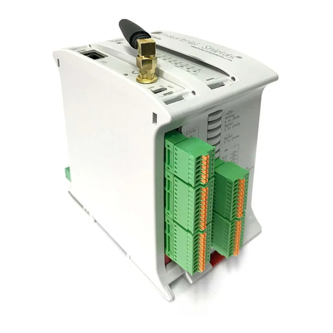
IS1 I/O-Modules
CPU & Power Module for Zone 2 / Div. 2 Series 9440/15
3
2011-06-01·BA00·III·en·02162278 / 9440609310www.stahl-ex.com Operating Instructions for the IS1-System
Replacing the Module
• Disconnect the power supply.
• Loosen the screws of the plug-in terminal X5.
• Pull out the terminal from the module.
• Pull out the fieldbus connections from the Sub-D socket.
• If necessary, remove the partition.
• Pull the red detent lever of the module upwards to unlock the
module.
• Remove the module vertically from the BusRail.
• Position the new module vertically onto the BusRail and
engage by slightly pressing it.
• If necessary, engage the partition between the modules.
• Connect the fieldbus again to the Sub-D connectors.
• Plug in the plug-in terminal X5 into the module and secure it
against loosening by means of screws.
Parameterisation and Commissioning
Start-Up
After connecting the power supply the CPU § Power Module
boots. After successful booting the LCD-display switches over to
the system level.
12258E00
Setting the Fieldbus Address
• Press „▲“ and „▼“ simultaneously.
✔The following indication is displayed:
12259E00
• Press „▲“ and „▼“ simultaneously.
✔The following indication is displayed:
12260E00
• Press „▲“ and „▼“ simultaneously.
✔The following indication is displayed:
12261E00
• Press the button „▲“ or „▼“ until the desired fieldbus address
is set.
•Press„▲“ and „▼“ simultaneously.
✔The following indication is displayed:
12262E00
•Press„▲“ and „▼“ simultaneously.
✔The settings are applied. The CPU & Power Module reboots.
or:
• Press the button „▲“ or „▼“.
✔The following indication is displayed:
12263E00
•Press„▲“ and „▼“ simultaneously.
✔The setting procedure is cancelled.
Commissioning of the Field Station
• Activate the cyclic data transfer with the master.
Display of Information on CPU & Power Module
• Press the „▲“ and „▼“ buttons simultaneously in order to
switch from the system level to the module level.
✔The following indication is displayed:
12259E00
• Select the desired module by pressing the button „▲“ or „▼“.
•Press„▲“ and „▼“ simultaneously.
✔The indication switches to the information level.
• Use the buttons „▲“ or „▼“ to switch between different
LCD-displays.
* Status information of the CPU & Power Module:
Before removing the CPU & Power Module the plug-in
terminal X5 must be de-energised and pulled out of the
CPU & Power Module to be replaced!
Parameterisation and commissioning of CPM and
connected I/O modules is carried out using the
automation system and Service Bus (optional).
Only the fieldbus address of the CPM must be set
directly at the module.
Using the buttons of the LCD-indication it is possible
✗to set the fieldbus address of the CPU & Power
Module and
✗to display information about the CPU & Power
Module and the I/O modules installed on the
BusRail.
Parameterisation and commissioning of CPM and
connected I/O modules is carried out using the
automation system and Service Bus (optional).
Only the fieldbus address of the CPM must be set
directly at the socket.
Using the buttons of the LCD-display in the socket it is
possible:
✗to set the fieldbus address of the CPU & Power
Module and
✗to display information about the CPU & Power
Module and the I/O modules installed on the
BusRail.
After setting the fieldbus address the CPU & Power
Module reboots again.
The fieldbus address is permanently saved and is also
available after reset or recommissioning.
The fieldbus address can be set only if the
CPU & Power Module is not in Data Exchange mode.
When pressing the button continuously the value is
being changed rapidly.
The setting range reaches from 0 to 127.
LCD-indication Function/display
12260E00
Status and fieldbus address of the
CPU & Power Module
12264E00
Connection type
12265E00
Status of the CPU & Power Module
(For possible status information
see Table "Status Information of
the CPU & Power Module")*
12266E00
Switching back to the module level
of the CPU & Power Module by
simultaneous pressing of the
buttons „▲“ and „▼“.
12267E00
Switching back to the main display
of the CPU & Power Module by
simultaneous pressing of the
buttons „▲“ and „▼“.
Status information on the
LCD-indication
Meaning
no error No error
hardware fail (1) Hardware fault detected
hardware fail (2) false hardware identification
hardware fail (3) no communication between CPR
and IOP
DataExch AS (2) Data Exchange with the
automation system
no DataExch no data exchange
config/para fail configuration or parameterisation
fault
quit DataExch no more data exchange
DataExch As Data Exchange with the
automation system, Configuration
via Profibus
accept changes ?
yes -> CPM reset
CPM information
Modbus V10-00
CPM status
config/para fail


