Stahl 9477/15 Series User manual
IS1 I/O-Module
Digital Output Modul Relais Ex nA Ausgänge, 8 Kanäle Reihe 9477/15
1
2015--·BA00·III·de·0201521 / 9477605310www.stahl-ex.com Betriebsanleitung für das IS1-System
09892E00
Digital Output Modu l Relais Ex nA Ausgänge, 8 Kan äle Reihe 9477/15
>8 Kanäle mit Ausgang: spannungsfreier Relaiskontakt, Schließer
>Ausgänge Ex nA (nicht funkend)
>Galvanische Trennung zwischen Ausgängen und System
>Modul unter Spannung austauschbar (hot swap)
*) geeignetes Gehäuse notwendig
Zone 01220 21 22
Class INEC 506
Zone 01220 21 22
Ex Schnittstelle X X
Installation in X X*)
Class III / III
Division 1212
Ex Schnittstelle X
Installation in X
Allgemeine Angaben
Hersteller
R. STAHL Schaltgeräte GmbH
Am Bahnhof 30
74638 Waldenburg, Germany
Telefon: +49 7942 943-0
Telefax: +49 7942 943-4333
Internet: www.stahl-ex.com
Service&Support: [email protected]
Weitere Informationen zum Modul
Weitere Informationen zum Modul finden Sie
✗im Automatisierungskatalog (168465 / 00 006 54 78 0) oder
✗im Internet unter www.stahl-automatisierung.de
Symbole
Sicherheitshinweise
In diesem Kapitel sind die wichtigsten Sicherheitsmaßnahmen
zusammengefasst. Es ergänzt die entsprechenden Vorschriften,
zu deren Studium das verantwortliche Personal verpflichtet ist.
Bei Arbeiten in explosionsgefährdeten Bereichen hängt die
Sicherheit von Personen und Anlagen von der Einhaltung aller
relevanten Sicherheitsvorschriften ab. Das Montage- und
Wartungspersonal trägt deshalb eine besondere Verantwortung.
Voraussetzung ist die genaue Kenntnis der geltenden Vorschrif-
ten und Bestimmungen.
✗die nationalen Sicherheits-, Unfallverhütungs-, Montage- und
Errichtungsvorschriften (z.B. IEC/EN 60079-14)
✗die allgemein anerkannten Regeln der Technik
✗die Sicherheitshinweise und Angaben dieses Dokuments,
die Kennwerte der Typschilder und die Hinweisschilder
✗die EG-Baumusterprüfbescheinigung (nach ATEX) bzw.
Konformitäts- oder Teilbescheinigung (nach bisheriger
Zulassung) und die darin enthaltenen besonderen
Bedingungen
✗dass Beschädigungen den Explosionsschutz aufheben
können
✗dass das Digital Output Modul Relais Typ 9477/15-08-12 nur
für den Einsatz in explosionsgefährdeten Bereichen der
Zone 2, Zone 22 oder im sicheren Bereich zugelassen ist.
✗dass das Modul, bei Einsatz in explosionsgefährdeten
Bereichen, in ein entsprechend bescheinigtes Gehäuse
eingebaut sein muss.
✗dass der Betrieb des Moduls neben einem Zone 1 Modul nur
dann erlaubt ist, wenn zwischen eigensicheren und nicht-
eigensicheren Stromkreisen ein Abstand von mindestens
50 mm eingehalten wird. Dies wird z.B. durch Montage einer
Trennwand (ID-Nr. 162740) zwischen den Modulen sicherge-
stellt.
✗dass das Stecken oder Ziehen der steckbaren Klemme nur
im spannungsfreien Zustand zulässig ist.
✗dass die max. Werte für Strom, Spannung und Leistung
(siehe Technische Daten) eingehalten werden. Der Schalt-
strom der Kontakte muss auf 2 A begrenzt sein
(z. B. Sicherung oder Strombegrenzung).
Verwenden Sie die Komponenten bestimmungsgemäß nur für
den zugelassenen Einsatzzweck (siehe Kapitel „Funktion/
Eigenschaften“). Fehlerhafter und unzulässiger Einsatz sowie
das Nichtbeachten der Hinweise dieses Dokuments schließen
eine Gewährleistung unsererseits aus.
Veränderungen an den Komponenten, die den Explosionsschutz
betreffen, sind nicht gestattet.
Komponenten dürfen nur in unbeschädigtem, trockenem und
sauberen Zustand eingebaut werden.
Normenkonformität
Die Komponenten entsprechen den folgenden Normen bzw. der
folgenden Richtlinie:
✗Richtlinie 94/9/EG
✗IEC 60079-0: 2004; IEC 60079-11: 2006; IEC 60079-15:
2005-03
Funktion/Eigenschaften
Die Ausgänge sind je ein potentialfreier Kontakt je Kanal. Sie
werden als Schließer betätigt. Logisch "0" = Kontakt offen;
logisch "1" = Kontakt geschlossen.
Die Anschlussklemmen des Moduls entsprechen Ex e.
Daran dürfen nur nicht-eigensichere Stromkreise angeschlossen
werden.
Die Kommunikation mit dem CPU & Power Modul erfolgt über die
Adress- und Datenleitungen der BusRail, die außerdem die
Leitungen zur Stromversorgung des Moduls enthält.
Die Schnittstelle des Digital Output Moduls zum internen Daten-
bus der BusRail ist redundant ausgeführt.
Achtung!
Diese Grafik kennzeichnet Hinweise, bei deren Nicht-
beachtung Ihre Gesundheit oder die Funktionsfähigkeit
des Gerätes bzw. der Komponente gefährdet ist.
Hinweis
Diese Grafik kennzeichnet wichtige
Zusatz_informationen, Tipps und Empfehlungen.
Beachten Sie als Anwender:
Digital Output Modul Relais Ex nA Ausgänge, 8 Kanäle Reihe 9477/15
22015--·BA00·III·de·0201521 / 9477605310www.stahl-ex.com Betriebsanleitung für das IS1-System
IS1 I/O-Module
Komponenten
Übersicht
08019E00
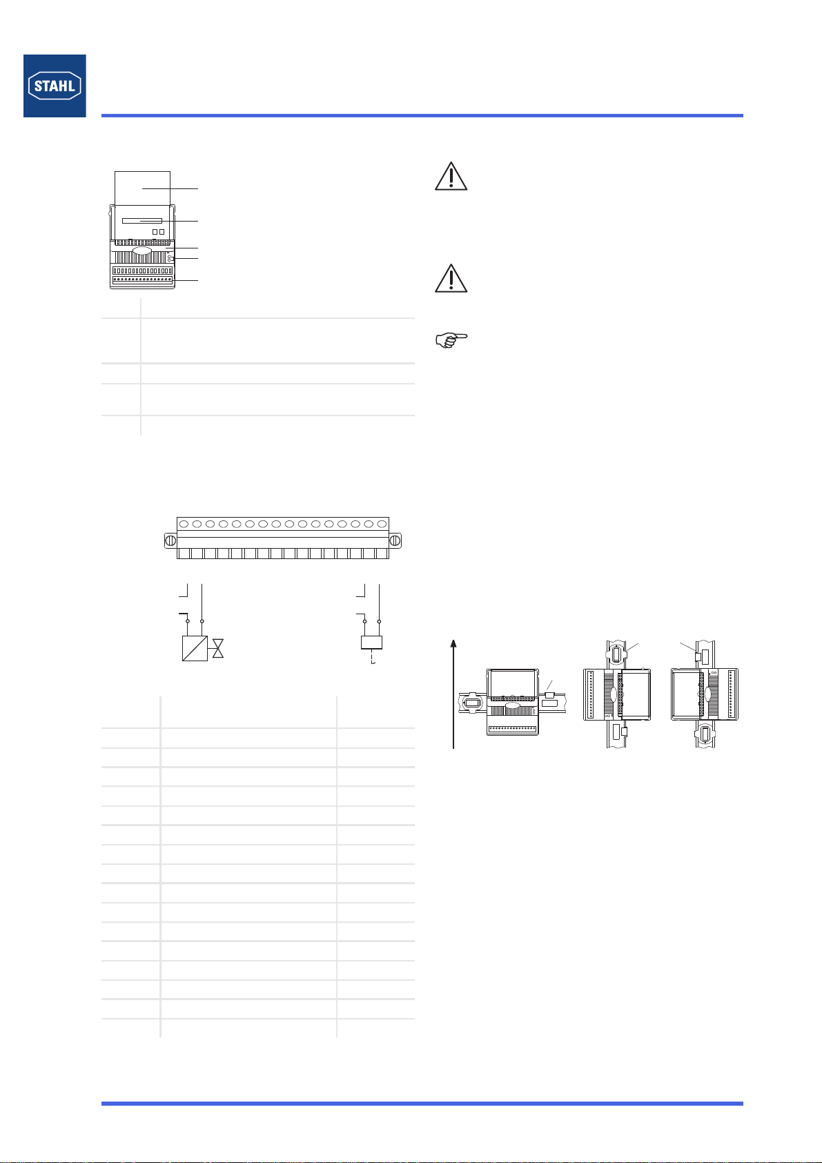
Steckbare Klemme X1
Die Module haben eine steckbare Klemme X1 zum Anschluss
von Feldgeräten.
Die steckbare Klemme X1 hat 16 Klemmen zum Anschluss der
Feldkabel.
Anschlussbelegung
Projektierung
✗Das Modul ist für IS1 Feldstationen bestimmt und darf in
explosionsgefährdeten Bereichen der Zone 2, Zone 22 oder
im sicheren Bereich installiert werden.
✗Bei Installation in explosionsgefährdeten Bereichen muss
das Modul in ein Gehäuse eingebaut werden, das den
Anforderungen entsprechend bescheinigt ist (z. B. R. STAHL
Typ 8126).
✗Das Modul wird zur bestimmungsgemäßen Verwendung auf
der IS1 BusRail installiert.
✗Eine Mischbestückung der BusRail mit verschiedenen
I/O-Modulen ist zulässig. Bei Montage eines Zone 2 Moduls
neben einem Zone 1 Modul (94../.2) muss eine Trennwand
(ID-Nr.: 162740) montiert werden!
✗Arbeiten an der steckbaren Klemme X1 und der Betrieb der
Module dürfen erst erfolgen, wenn die Trennwand montiert
ist.
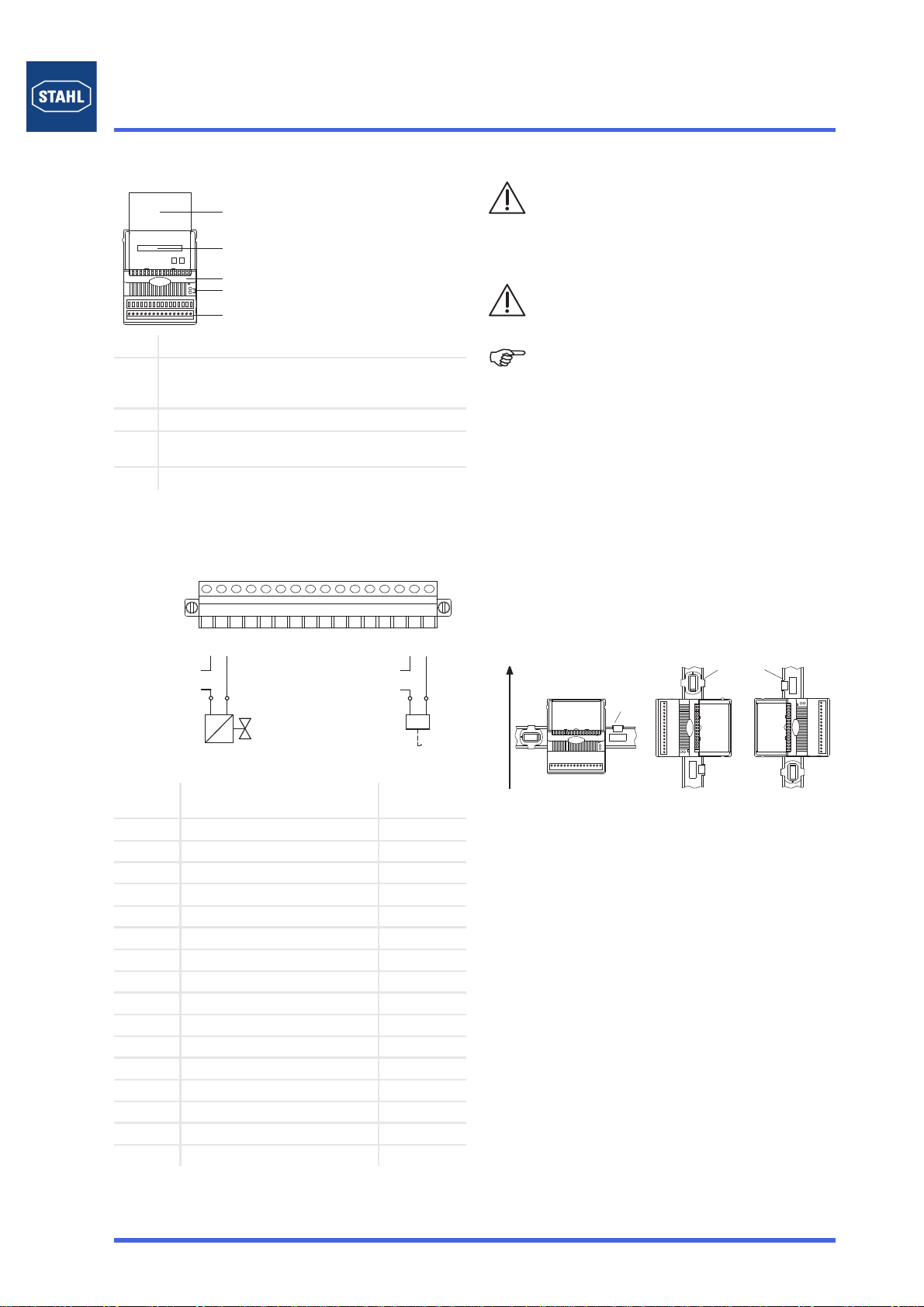
✗Der Betrieb des Moduls ist nur in den drei Montagelagen
zulässig:
Montagerichtung oben:
✗Die BusRail Abschlüsse BusRail Beginn Sub-D
Typ 9494/A2-B0 und BusRail Ende Sub-D Typ 9494/A2-E0
dürfen nicht unmittelbar neben dem Modul montiert werden.
Zwischen dem Modul und den BusRail Abschlüssen muss
mindestens ein Modulsteckplatz Abstand eingehalten
werden!
✗An den angeschlossenen Stromkreisen darf nur im
spannungsfreien Zustand oder zu Wartungszwecken unter
Beachtung von IEC/EN 60079-17 Pkt. 4.6 in der Zone 2
gearbeitet werden. Die steckbare Klemme X1 für die Aus-
gangsstromkreise muss durch Verschraubung gegen Lösen
gesichert werden.
✗Die Schirme der Feldverkabelung müssen mit dem Potential-
ausgleich des explosionsgefährdeten Bereichs verbunden
werden!
Dazu müssen die Schirme der Feldverkabelung möglichst
nahe der Eintrittstelle mit den, in den Gehäusen installierten,
Schirmschienen verbunden werden!
Die Schirmschienen müssen ebenfalls nahe der Eintrittstel-
len der Feldverkabelung auf möglichst kurzem Weg mit der
Montageplatte verbunden werden!
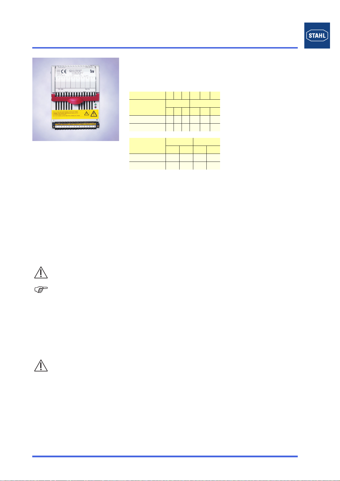
1 Abdeckklappe mit Einlegeschild (geöffnet)
2 Angaben zum Modul (Seriennummer, Hardware-
Revisionsnummer, Software-Revisionsnummer, Her-
stelldatum, z. B.: 123456DE9999 Rev.A 01-01 0508)
3 Rasthebel zum Entfernen des Moduls von der BusRail
4 LED zur Status- bzw. Fehleranzeige (weitere Informa-
tionen siehe „LED Anzeigen und Fehlerbehebung“)
5 Steckbare Klemme X1
06309E00
Kanal Nr. Funktion Stecker X1
Klemme Nr.
0Kontakt Schließer A 1
0Kontakt Schließer B 2
1Kontakt Schließer A 3
1Kontakt Schließer B 4
2Kontakt Schließer A 5
2Kontakt Schließer B 6
3Kontakt Schließer A 7
3Kontakt Schließer B 8
4Kontakt Schließer A 9
4Kontakt Schließer B 10
5Kontakt Schließer A 11
5Kontakt Schließer B 12
6Kontakt Schließer A 13
6Kontakt Schließer B 14
7Kontakt Schließer A 15
7Kontakt Schließer B 16
1
2
3
4
5
......
max. 250 V
7
max. 250 V
0
X1
1 2 3 4 5 6 7 8 9 10 111213141516
Die nationalen Errichtungsbestimmungen
(z. B. IEC/EN 60079-14) müssen beachtet werden.
Eigensichere und nicht-eigensichere Stromkreise
dürfen nicht in einem gemeinsamen Kabelkanal geführt
werden!
Zwischen Anschlussteilen eigensicherer und nicht-
eigensicherer Stromkreise muss ein Abstand von
mindestens 50 mm (Fadenmaß) eingehalten werden!
Sicherstellen, dass die max. Werte für Strom,
Spannung und Leistung (siehe Technische Daten)
eingehalten werden.
Der Schaltstrom muss auf 2 A begrenzt sein
(z. B. Sicherung oder Strombegrenzung).
In der Abdeckklappe befindet sich ein Einlegeschild, in
das die Zuordnung der Feldgeräte zu den Kanälen
eingetragen werden kann.
Die Beschriftung des Einlegeschilds kann z. B. über
den IS Wizard erfolgen.
05683E00
BusRail
BusRail

IS1 I/O-Module
Digital Output Modul Relais Ex nA Ausgänge, 8 Kanäle Reihe 9477/15
3
2015--·BA00·III·de·0201521 / 9477605310www.stahl-ex.com Betriebsanleitung für das IS1-System
Montage und Installation
Montage auf BusRail
• Feldgeräte an steckbarer Klemme X1 anschließen.
• Schirme der Feldverkabelung möglichst nahe der Eintritt-
stelle auf Erdungsschienen auflegen.
• Modul senkrecht auf vorgesehenen Steckplatz der BusRail
aufsetzen.
• Modul durch leichtes Drücken einrasten.
• Gegebenenfalls Trennwand zwischen Modulen einrasten.
• Steckbare Klemme X1 auf Modul stecken und mit Schrauben
gegen Lockern sichern.
Austausch des Moduls
• Schrauben der steckbaren Klemme X1 lösen.
• Klemme von Modul abziehen.
• Gegebenenfalls Trennwand entfernen.
• Roten Rasthebel des Moduls nach oben ziehen, um das
Modul zu entriegeln.
• Modul senkrecht von BusRail abziehen.
• Neues Modul senkrecht auf BusRail setzen und durch
leichtes Drücken einrasten.
• Gegebenenfalls Trennwand zwischen Modulen einrasten.
• Steckbare Klemme X1 auf Modul stecken und mit Schrauben
gegen Lockern sichern.
Wartung und Instandhaltung
Das Modul ist wartungsfrei.
• Beachten Sie die bestimmungsgemäße Funktion.
• Halten Sie sich an die Richtlinien nach IEC/EN 60079-17.
• Halten Sie die zulässigen Temperaturen gemäß
IEC/EN 60079-0 ein.
Reparatur
Für die Reparatur schicken Sie das Modul an Ihre zuständige
Vertriebsorganisation (Adresse siehe www.stahl.de).
Die Reparatur darf nur durch den Hersteller durchgeführt
werden!
Transport und Lagerung
Transport und Lagerung sind nur in Originalverpackung
gestattet.
Entsorgung
Die nationalen Errichtungsbestimmungen
(z. B. IEC/EN 60079-14) müssen beachtet werden.
Eigensichere und nicht-eigensichere Stromkreise
dürfen nicht in einem gemeinsamen Kabelkanal geführt
werden!
Zwischen Anschlussteilen eigensicherer und nicht-
eigensicherer Stromkreise muss ein Abstand von
mindestens 50 mm (Fadenmaß) eingehalten werden!
Die Schirme der Feldverkabelung müssen mit dem
Potentialausgleich des explosionsgefährdeten
Bereichs verbunden werden!
Dazu müssen die Schirme der Feldverkabelung mög-
lichst nahe der Eintrittstelle mit den, in den Gehäusen
installierten, Schirmschienen verbunden werden!
Die Schirmschienen müssen ebenfalls nahe der Ein-
trittstellen der Feldverkabelung auf möglichst kurzem
Weg mit der Montageplatte verbunden werden!
Das Modul kann während des Betriebs im explosions-
fähigen Bereich gefahrlos gesteckt oder gezogen wer-
den (hot swap).
Ein Anschlussplan ist auf der Rückseite des Einlege-
schilds in der Abdeckklappe abgedruckt.
Der Betrieb des Moduls ist nur in folgenden Montage-
lagen zulässig:
Montage senkrecht mit steckbarer Klemme unten, links
oder rechts.
Vor dem Entfernen der Trennwand zwischen dem
Modul und einem Zone 2 Modul, muss die steckbare
Klemme X1 vom auszutauschenden Modul abgezogen
werden!
Beim Austausch des Moduls durch ein baugleiches
Modul werden die bisherigen Parameter übernommen.
Es sind keine weiteren Einstellungen notwendig.
Beim Austausch des Moduls durch ein anderes Modul
wird das Modul am Steckplatz richtig erkannt, da die
bisherigen Parameter nicht zu diesem Modul passen,
meldet das Modul einen Konfigurationsfehler.
Das Modul muss entweder neu parametriert werden
oder es muss ein Modul des richtigen Typs verwendet
werden.
Beachten Sie die nationalen Abfallbeseitigungs-
vorschriften!

Digital Output Modul Relais Ex nA Ausgänge, 8 Kanäle Reihe 9477/15
42015--·BA00·III·de·0201521 / 9477605310www.stahl-ex.com Betriebsanleitung für das IS1-System
IS1 I/O-Module
LED Anzeigen und Fehlerbehebung
LED grün
“RUN“
LED rot
“ERR“
I/O-Modul Zustand Fehlerquelle Mögliche Behebung
Ein Aus Alle Signale OK keine --
Ein Blinkt Signal Diagnose Signal(e) gestört Ursache für Signaldiagnose (Kurz-
schluss, Leitungsunterbrechung
etc.) beseitigen.
Blinkt Aus In Bereitschaft (nach dem
Einschalten, aber noch ohne
Datenaustausch mit dem
Master)
• Modul ist in Ordnung, jedoch
noch nicht für den zyklischen
Datenaustausch bereit (es ist
noch kein Parametersatz
vorhanden).
• Ausgänge in leistungslosem
Zustand.
Zyklischen Datenverkehr mit dem
Master in Betrieb setzen.
Master, Busverbindung und CPM
prüfen.
Blinkt Blinkt Data Exchange wurde verlas-
sen (Ausgänge in Sicherheits-
stellung)
Zyklischer Datenverkehr mit dem
Master ist unterbrochen.
Zyklischen Datenverkehr mit dem
Master in Betrieb setzen.
Master, Busverbindung und CPM
prüfen.
Blinkt Ein Konfigurationsfehler Konfiguration ist nicht in Ordnung
oder falsches Modul ist gesteckt.
Konfiguration des Masters ändern
oder richtiges Modul stecken.
Aus Ein oder
Blinkt
I/O-Modul Hardwarefehler • Hardware-Check-Fehler
• Eprom-Fehler
• EEprom-Fehler
I/O-Modul tauschen.
Aus Aus Aus Keine Versorgungsspannung am
I/O-Modul vorhanden oder
I/O-Modul defekt.
• Versorgung des CPM prüfen.
• CPM prüfen.
• BusRail prüfen.
• I/O-Modul richtig auf BusRail.
aufrasten.
• I/O-Modul tauschen.
Hinweis
Wenden Sie sich an Ihre zuständige Vertriebsniederlassung oder unsere Service-Abteilung
beheben lässt.
Technische Daten
Bescheinigungen
IECEx
ATEX
IECEx PTB 06.0001X
PTB 01 ATEX 2187
Explosionsschutz
IECEx
ATEX
Ex nA nC nL [ib] IIC T4
EII 3 (2) G Ex nA nC ic [ib Gb] IIC T4 Gc
Weitere Bescheinigungen USA (FM), Kanada (CSA), Russland (CTB), Weißrussland (Gospromnadzor),
Kasachstan (JSC), Brasilien (INMETRO), Schiffszulassung (DNV, ABS, GL, ClassNK)
Weitere Angaben siehe Bescheinigungen
Galvanische Trennung
zwischen Hilfsenergie und
Systemkomponenten
1500 V AC
zwischen zwei Input /
Output Modulen
500 V AC
zwischen Eingängen und
Systemkomponenten
375 V AC
Ausgänge untereinander 250 V AC
Ex nA-Ausgänge
Anzahl Kanäle 8
Kontakt Schließer
Maximale Schaltspannung
Maximaler Schaltstrom
Maximale Schaltleistung
Minimale Schaltspannung 5 V AC / DC
Minimaler Schaltstrom 2 mA
Lebensdauer
250 V AC 30 V DC 110 V DC 220 V DC
2 A 2 A 0,3 A 0,12 A
100 VA 60 W 33 W 26 W

IS1 I/O-Module
Digital Output Modul Relais Ex nA Ausgänge, 8 Kanäle Reihe 9477/15
5
2015--·BA00·III·de·0201521 / 9477605310www.stahl-ex.com Betriebsanleitung für das IS1-System
elektrisch
mechanisch
Ex nA-Ausgänge
Maximale
Kontaktbelastung ohne
Beschädigung der
Goldauflage
bis 24 V / 1,5 W
Sichere Kontaktgabe bei
beschädigter Goldauflage
ab 12 V / 1,5 W
Anschlüsse 2,5 mm2flexibel
Kennwerte
Maximale
Signalverzögerung vom
internen Bus zum
Ausgang
10 ms
MTBF nach MIL 76,2 Jahre bei + 40 ºC
Einstellungen
Sicherheitsstellung
(Ausgang bei
Kommunikationsfehler)
ON, OFF, letzten Wert halten
Abrufbare Parameter Hersteller, Typ, Version, Seriennummer
Diagnosen
Modulfehler • Fehler interner Bus primär
• Fehler interner Bus redundant
• keine Antwort
• Konfiguration ungleich Modul
• Hardwarefehler
Hilfsenergie
Verhalten bei
Unterspannung
Ausgang = AUS
Maximale
Leistungsaufnahme
4,8 W
Maximale Verlustleistung 4,8 W
Mechanische Daten
Modulgehäuse Polyamid 6GF
Brandfestigkeit (UL 94) V2
Schutzart (IEC 60529)
Module IP30
Anschlüsse IP20
Elektrischer Anschluss
Ex nA Feldsignale Steckbare Klemmen 16 polig mit Arretierung, 2,5 mm2, Schraub- oder Federzugausführung
Bediener-Schnittstelle
Betrieb LED grün "RUN"
Fehler LED rot "ERR"
Einbaubedingungen
Montageart auf 35 mm DIN Schiene NS 35/15
Einbaulage waagrecht und senkrecht
Umgebungsbedingungen
Umgebungstemperatur - 20 ... + 65 °C
Lagertemperatur - 40 ... + 70 °C (in einer Höhe < 2000 m)
Maximale relative
Luftfeuchte
95 % (keine Betauung)
Vibration, sinusförmig
(IEC EN 60068-2-6)
1 g im Frequenzbereich 10 ... 500 Hz
2 g im Frequenzbereich 45 ... 100 Hz
Schock, halbsinusförmig
(IEC EN 60068-2-27)
15 g (3 Schocks pro Achse und Richtung)
Elektromagnetische
Verträglichkeit
Geprüft nach folgenden Normen und Vorschriften:
EN 61326-1 (2013) IEC 1000-4-1...6, NAMUR NE 21
Technische Daten
bei max 2 A
AC 1 - Belastung )0,6 x 10⁶Schaltspiele
DC 1 - Belastung
(ohmsche Last)
)100 x 103Schaltspiele
)10 x 106Schaltspiele

Digital Output Modul Relais Ex nA Ausgänge, 8 Kanäle Reihe 9477/15
62015-04-10·BA00·III·de·04201521 / 9477605310www.stahl-ex.com Betriebsanleitung für das IS1-System
IS1 I/O-Module
Projektierungshinweis • Das Modul ist für I.S. 1 Feldstationen bestimmt und darf nur in Zone 2 / Division 2 oder im
sicheren Bereich installiert werden. Für Zone 2 ist ein Gehäuse mit Schutzart mindestens IP54
erforderlich. Das Modul wird auf die BusRail des I.S. 1 Systems gesteckt.
• Es wird empfohlen das Modul 9477/15 neben dem CPM (9440) anzuordnen. Um den
Trennabstand von )50 mm zu den Anschlussklemmen der Ex i Module einzuhalten, ist eine
Trennwand (162740) erforderlich.
• An das Modul dürfen nicht-eigensichere Stromkreise angeschlossen werden unter Einhaltung
der maximalen Werte für Strom, Spannung und Leistung (siehe technische Daten). Der
Schaltstrom der Kontakte muss auf 2 A begrenzt sein (z. B. Sicherung oder Strombegrenzung).
Technische Daten
Maßzeichnungen (alle Maße in mm / Zoll) - Änderungen vorbehalten
09879E00
67 mm / 2.64 "
96,5 mm / 3.8 "
128 mm / 5.04 "
Zubehör und Ersatzteile
Bezeichnung Abbildung Beschreibung Art.Nr.
Steckbare Klemme
09898E00
2,5 mm2mit Arretierung, 16 polig, Schraubanschluss, schwarz,
zum Anschluss der Feldsignale an I/O Module,
für nicht eigensichere Feldstromkreise
Achtung: Nur für I/O Modul 9477/15
Ausführung mit Warnschild
Beschriftung: 1 ... 16
162704
09899E00
2,5 mm2mit Arretierung, 16 polig, Federkraftanschluss, schwarz,
zum Anschluss der Feldsignale an I/O Module,
für nicht eigensichere Feldstromkreise, incl. Prüfbuchsen
Achtung: Nur für I/O Modul 9477/15
Ausführung mit Warnschild
Beschriftung: 1 ... 16
162706
Beschriftungsstreifen
05869E00
„FB No ... Mod No ...“ für steckbare Klemme, 26 Stück auf Bogen 162788
DIN A4 Bogen
09900E00
für Beschriftungsschild an I/O Modulen; 6 Schilder pro Bogen;
Ausdruck IS Wizard; Verpackungseinheit = 20 Bogen
162832
Trennwand
02078E00
Zur Montage zwischen eigensicheren und nicht eigensicheren
Anschlüssen der I/O-Module um die 50 mm Fadenmaß einzuhalten
162740
2015-11-03·BA00·III·de·05
IS1 I/O-Modules
Digital Output Module Relay Ex nA Outputs, 8 Channels Series 9477/15
1
2015-11-03·BA00·III·en·05201521 / 9477605310www.stahl-ex.com Operating Instructions for the IS1-System
09892E02
Digital Output Modu le Relay Ex nA Outputs, 8 Channe ls Series 9477/15
>8 channels with output: volt-free relay contact, normally open
>Outputs Ex nA (non-sparking)
>Galvanic isolation between outputs and system
>Module can be replaced in operation (hot swap)
*) suitable enclosure necessary
Zone 01220 21 22
Class INEC 506
Zone 01220 21 22
Ex interface X X
Installation in X X*)
Class III / III
Division 1212
Ex interface X
Installation in X
General Information
Manufacturer
R. STAHL Schaltgeräte GmbH
Am Bahnhof 30
74638 Waldenburg, Germany
Telephone: +49 7942 943-0
Fax: +49 7942 943-4333
Internet: www.stahl-ex.com
Service&Support: [email protected]
Further Information on the Module
Further information on the module you will find
✗in the automation catalogue (168465 / 00 006 54 78 0) or
✗on the internet at www.stahl-automatisierung.de
Symbols
Safety Instructions
The most important safety instructions are summarised in this
section. They supplement the corresponding regulations which
the personnel in charge must study. When working in hazardous
areas, safety of the personnel and plant depends on complying
with all relevant safety regulations. Assembly and maintenance
staff working on installations therefore have particular
responsibility.
A precise knowledge of the applicable standards and regulations
is required.
✗the national safety, accident prevention, assembly and
installation regulations (e.g. IEC/EN 60079-14)
✗generally recognised technical regulations,
✗the safety instructions and information of this document,
characteristic values of the type labels and the instruction
plates
✗the EC Type Examination Certificate (according to ATEX) or
conformity or partial certificate (after previous approval) and
special conditions contained in it
✗that any damage may render explosion protection null and
void.
✗that the Digital Output Module Relay of Type 9477/15-08-12
is certified for application in hazardous areas of Zone 2, Zone
22 or in the safe area.
✗when used in hazardous areas the module has to be fitted
into an enclosure which is certified appropriately to the
requirements.
✗that the operation of the module near a Zone 1 module is only
allowed if there is a distance of at least 50 mm left between
intrinsically safe and non-intrinsically safe circuits. This is
ensured by means of a partition assembled between the
modules (ID-No.: 162740).
✗that plugging in or pulling out the plug-in terminal in a
non-energy limited electric circuit is permitted only if
de-energised.
✗that the max. values for current, voltage and power
(see Technical Data) must be observed. The switching
current of the contacts must be limited to 2 A (e.g. fuse or
current limitation).
Use the component in accordance with its designated use and for
its intended purpose only (see chapter "Function/
Characteristics"). Incorrect and impermissible use or non-
compliance with this document invalidates our warranty
provision.
No modifications or alterations to the components, impairing their
explosion protection, are permitted.
The components are to be fitted only if they are undamaged and
clean.
Conformity to Standards
The components comply with the following standards and
directive:
✗Directive 94/9/EC
✗IEC 60079-0: 2004; IEC 60079-11: 2006; IEC 60079-15:
2005-03
Function/Characteristics
Operation: The output is a volt-free contact per channel.
It is operated as normally open. Logical "0" = contact open;
logical "1" = contact closed.
The terminals are increased safety Ex e. There may only
non-intrinsically safe circuits be connected.
Communication with the CPU & Power Module is achieved using
the address and data lines of the BusRail, which contain in
addition the lines for the power supply to the module.
The interface of the Digital Output Module with the internal data
bus of the BusRail is designed with redundancy.
Attention!
This symbol marks notes whose non-observance will
endanger your health or functioning of the device.
Note
This symbol marks important additional information,
tips and recommendations.
As the user, please note:
Digital Output Module Relay Ex nA Outputs, 8 Channels Series 9477/15
22015-11-03·BA00·III·en·05201521 / 9477605310www.stahl-ex.com Operating Instructions for the IS1-System
IS1 I/O-Modules
Components
Overview
08019E00
Plug-in terminal X1
The modules have a plug-in terminal X1 for connection of the field
devices.
The plug-in terminal X1 has 16 terminals for connection of the
field cables.
Terminal assignment
Designing
✗The module is intended for IS 1 field stations and can be
installed in hazardous areas of Zone 2, Zone 22 or in the safe
area.
✗For installation in hazardous areas the module has to be
fitted into an enclosure which is certified appropriate to the
requirements (e.g. R. STAHL Type 8126).
✗The module is installed for designated use on the
IS1 BusRail.
✗A mixed arrangement of the BusRail with different
I/O modules is permitted. When assembling a Zone 2 module
near Zone 1 module (94../.2) it is required to assemble a
partition (ID-No.: 162740)!
✗Work on the plug-in terminal X1 and operation of the module
can be performed after the partition has been installed.
✗Operation of the module is only admissible in three assembly
positions:
assembly direction above:
✗The BusRail terminals, BusRail Begin Sub-D of
Type 9494/A2-B0 and BusRail End Sub-D of
Type 9494/A2-E0 must not be assembled directly near the
module. Between the module and the BusRail terminals
there must be a distance of at least one module slot!
✗Any operations at the connected electric circuits are
permitted only if de-energised and any operations for
maintenance purposes in Zone 2 must be carried out only in
accordance with IEC/EN 60079-17 Part 4.6. Secure the plug-
in terminal X1 for the output circuits by means of a cable
gland against loosening.
✗The screens on the fieldbus cabling must be connected to the
equipotential bonding system of the hazardous area!
For this purpose the screens on the fieldbus cabling must be
connected to the screen bars installed in the enclosures as
close as possible to the entry point! The screen bars must
also be connected to the mounting plate close to the entry
points for the fieldbus cabling by the shortest possible route!
1 Protective cover with symbol label (opened)
2 Information on the module (serial number, hardware
revision number, software revision number, manufac-
turing date, e.g.: 123456DE9999 Rev.A 01-01 0508)
3 Detent lever for removing the module from the BusRail
4 LED for status or fault indication (further information
see "LED indication and Troubleshooting")
5 Plug-in terminal X1
06309E00
Channel
No.
Function Plug X1
terminal No.
0NO contact A 1
0NO contact B 2
1NO contact A 3
1NO contact B 4
2NO contact A 5
2NO contact B 6
3NO contact A 7
3NO contact B 8
4NO contact A 9
4NO contact B 10
5NO contact A 11
5NO contact B 12
6NO contact A 13
6NO contact B 14
7NO contact A 15
7NO contact B 16
1
2
3
4
5
......
max. 250 V
7
max. 250 V
0
X1
1 2 3 4 5 6 7 8 9 10 111213141516
The national installation instructions
(e.g. IEC/EN 60079-14) must be observed.
Intrinsically-safe and non-intrinsically safe circuits must
not be used in a common cable duct!
Ensure that there is a distance of at least 50 mm
between connection facilities of intrinsically-safe and
non-intrinsically safe circuits!
that the max. values for current, voltage and power
(see Technical Data) must be observed.
The switching current of the contacts must be limited to
2 A (e.g. fuse or current limitation).
In the protective cover there is a symbol label, which
can be used for entering the assignment of the field
devices to the channels.
Labelling of the symbol label can be performed,
for example by means of the IS Wizard.
05683E00
BusRail
BusRail
IS1 I/O-Modules
Digital Output Module Relay Ex nA Outputs, 8 Channels Series 9477/15
3
2015--·BA00·III·en·0201521 / 9477605310www.stahl-ex.comOperating Instructions for the IS1-System
Assembly and Installation
Assembly on the BusRail
• Connect the field devices to the plug-in terminal X1.
• Connect screens on the fieldbus cabling to earth bars as
close as possible to the entry point.
• Position the module vertically at the intended slot of the
BusRail.
• Engage the module by slightly pressing it.
• If necessary, engage the partition between the modules.
• Plug in the plug-in terminal X1 into the module and secure it
by means of screws against loosening.
Replacing the Module
• Loosen the screws of the plug-in terminal X1.
• Pull out the terminal from the module.
• If necessary, remove the partition.
• Pull the red detent lever of the module upwards to unlock the
module.
• Remove the module vertically from the BusRail.
• Position the new module vertically onto the BusRail and
engage it by slightly pressing it.
• If necessary, engage the partition between the modules.
• Plug in the plug-in terminal X1 into the module and secure it
by means of screws against loosening.
Maintenance and Servicing
The module is maintenance-free.
• Observe the function according to designated use.
• Adhere to the directives according to IEC/EN 60079-17.
• Adhere to permissible temperatures according to
IEC/EN 60079-0.
Repair
For repair send the module to the responsible sales organisation
(address see www.stahl.de).
Repair is to be performed only by the manufacturer.
Transport and Storage
Transport and storage are permitted only in the original
packaging.
Disposal
The national installation instructions
(e.g. IEC/EN 60079-14) must be observed.
Intrinsically-safe and non-intrinsically safe circuits must
not be used in a common cable duct!
Ensure that there is a distance of at least 50 mm
between connection facilities of intrinsically-safe and
non-intrinsically safe circuits!
The screens on the fieldbus cabling must be connected
to the equipotential bonding system of the hazardous
area!
For this purpose the screens on the fieldbus cabling
must be connected to the screen bars installed in the
enclosures as close as possible to the entry point!
The screen bars must also be connected to the
mounting plate close to the entry points for the fieldbus
cabling by the shortest possible route!
The Module can be safely connected or disconnected
during operation in a hazardous area (hot swap).
A connection diagram is imprinted on the rear side of
the symbol label at the protective cover.
Operation of the module is permissible only in the
following assembly positions:
Vertical assembly with a plug-in terminal below, on the
left or right.
Before removing the partition between the module and
a Zone 2 module the plug-in terminal X1 must be pulled
out of the module to be replaced!
When replacing the module with a module identical in
construction the previous parameters are applied.
No further settings are necessary.
When replacing the module by another module it is
identified correctly at the slot, since the previously set
parameters do not suit this module, it reports a
configuration fault. The module must be either
parameterised again or it is necessary to connect the
module of the right type.
Observe the national standards for refuse disposal.

Digital Output Module Relay Ex nA Outputs, 8 Channels Series 9477/15
42015--·BA00·III·en·0201521 / 9477605310www.stahl-ex.com2perating Instructions for the IS1-System
IS1 I/O-Modules
LED Indications and Troubleshooting
LED green
"RUN"
LED red
"ERR"
I/O Module status Source of fault Possible troubleshooting solution
On Off All signals are OK none --
On Blinks Signal diagnosis Signal(s) is(are) disrupted Eliminate the reason for the signal diag-
nosis (short circuit,
line disconnection etc.).
Blinks Off In standby (switched on but no data
exchange with master yet)
• The module is in proper
condition but is not ready for
cyclic data exchange yet (there is no
parameter set available yet).
• The outputs are inactive.
Activate the cyclic data transfer with the
master.
Check the master, bus connection and
CPM.
Blinks Blinks Data Exchange has been quit (the
outputs are in safety
position)
Cyclic data transfer with master is inter-
rupted.
Activate the cyclic data transfer with the
master.
Check the master, bus connection and
CPM.
Blinks On Configuration fault Configuration is not correct or a
false module is connected.
Change configuration of master or con-
nect to the right module.
Off On or blinks I/O module hardware fault • Hardware check fault
• Eprom fault
• EEprom fault
Replace the I/O module.
Off Off Off No supply voltage at the I/O module or
defective I/O module.
• Check the power supply of the CPM.
• Check the CPM.
• Check the BusRail.
• Engage the I/O module correctly on
the BusRail.
• Replace the I/O module.
Note
Contact the responsible sales subsidiary or our service department (support.instrum[email protected]) if the fault cannot
be eliminated using available troubleshooting options.
Technical Data
Certificates
IECEx
ATEX
IECEx PTB 06.0001X
PTB 01 ATEX 2187
Explosion Protection
IECEx
ATEX
Ex nA nC nL [ib] IIC T4
EII 3 (2) G Ex nA nC ic [ib Gb] IIC T4 Gc
Further certificates USA (FM), Canada (CSA), Russia (CTB), Belarus (Promatomnadzor), Kazakhstan (JSC), Brazil
(INMETRO), ship approval (DNV, ABS, GL, ClassNK)
Further information see certificates
Galvanic isolation
between power supply
and system components
1500 V AC
between two input / output
modules
500 V AC
between inputs and
system components
375 V AC
Outputs interconnected 250 V AC
Ex nA outputs
Number of channels 8
Contact NO
Maximum switching
voltage
Maximum switching
current
Maximum switching
capacity
Minimum switching
voltage
5 V AC / DC
Minimum switching
current
2 mA
Service life
electrical
mechanical
Ex nA outputs
250 V AC 30 V DC 110 V DC 220 V DC
2 A 2 A 0.3 A 0.12 A
100 VA 60 W 33 W 26 W
at max. 2 A
AC 1 - load )0.6 x 10⁶switching cycles
DC 1 - load
(resistive load)
)100 x 103switching cycles
)10 x 106switching cycles

IS1 I/O-Modules
Digital Output Module Relay Ex nA Outputs, 8 Channels Series 9477/15
5
2015--·BA00·III·en·0201521 / 9477605310www.stahl-ex.comOperating Instructions for the IS1-System
Maximum contact load
without damage to gold
plating
at 24 V / 1.5 W
Safe contact operation
with damaged gold plating
from 12 V / 1.5 W
Connections 2.5 mm2flexible
Characteristic values
Maximum signal delay
from internal bus to
outputs
10 ms
MTBF acc. to MIL 76.2 years (at +40 °C)
Settings
Safety position (output
with communication error)
ON, OFF, hold last value
Retrievable parameters Manufacturer, type, version, serial number
Diagnoses
Module faults • Internal primary bus faults
• Internal redundant bus faults
• No response
• Module does not correspond to configuration
• Hardware fault
Power supply
Defined behaviour during
undervoltage
Output = OFF
Maximum power
consumption
4.8 W
Maximum power
dissipation
4.8 W
Mechanical data
Module enclosure Polyamide 6GF
Fire protection class
(UL 94)
V2
Degree of protection
(IEC 60529)
Modules IP30
Connections IP20
Electrical connection
Ex nA / NI field signals Plug-in terminals 16-pole with catch, 2.5 mm2/ up to 14 AWG, screw or spring type
Operator interface
Operation LED green "RUN"
Fault LED red "ERR"
Installation conditions
Mounting type on 35 mm DIN rail NS 35/15
Installation position horizontal and vertical
Ambient Conditions
Ambient temperature - 20 ... + 65 °C
Storage temperature - 40 ... + 70 °C (use at height < 2000m)
Maximum relative
humidity
95 % (no condensation)
Vibration, sinusoidal
(IEC EN 60068-2-6)
1 g in frequency range between 10 ... 500 Hz
2 g in frequency range 45 ... 100 Hz
Shock, semi-sinusoidal
(IEC EN 60068-2-27)
15 g (3 shocks per axis and direction)
Electromagnetic
compatibility
Tested according to the following standards and regulations:
EN 61326-1 (2013) IEC 1000-4-1...6, NAMUR NE 21
Engineering notes • The module is intended for I.S. 1 field stations and may only be installed in Zone 2 / Division 2 or
in the safe area. For use in Zone 2, an enclosure with degree of protection of at least IP54 is
required. The module is plugged onto the BusRail of the I.S. 1 system.
• It is recommended to position the module 9477/15 next to the CPM (9440). In order to maintain
the distance of )50 mm / 2 in to the connection terminals of the I.S. module, a partition (162740)
is required.
• Non-intrinsically safe circuits may be connected to the module, provided that the maximum
values of current, voltage and power (refer to technical data) are adhered to. The switching
current of the contacts must be limited to 2 A (e.g. fuse or current limitation).
Technical Data

Digital Output Module Relay Ex nA Outputs, 8 Channels Series 9477/15
62015-04-10·BA00·III·en·04201521 / 9477605310www.stahl-ex.com Operating Instructions for the IS1-System
IS1 I/O-Modules
Dimensional Drawings (All Dimensions in mm / inches) - Subject to Alterations
09879E00
67 mm / 2.64 "
96,5 mm / 3.8 "
128 mm / 5.04 "
Accessories and Spare Parts
Designation Illustration Description Art. no.
Plug-in terminal
09898E00
2.5 mm2with catch, 16-pole, screw connection, black, for connecting
the field signals to I/O modules, for non-intrinsically safe field circuits
Attention: Only for I/O module 9477/15
Version with warning sign
Labelling: 1 ... 16
162704
09899E00
2.5 mm2with catch, 16-pole, spring connection, black, for connecting
the field signals to I/O modules, for non-intrinsically safe field circuits
including test jacks
Attention: Only for I/O module 9477/15
Version with warning sign
Labelling: 1 ... 16
162706
Labelling strips
05869E00
„FB No ... Mod No ...“ for plug-in terminals, sheet with 26 labels 162788
DIN A4 sheet
09900E00
For I/O module labels; 6 labels each sheet; print out with IS Wizard
software; packaging unit = 20 sheets
162832
Partition
02078E00
For assembly between intrinsically safe and non-intrinsically safe
connectors of the I/O modules, in order to adhere to the required
50 mm distance
162740
2015-11-03·BA00·III·en·05
08.02. Reistle
2013
9400 6 031 002 1
none
FM
Kaiser
1 of 30
02 26.02.2014 Bagusch
01 17.02.2014 Bagusch
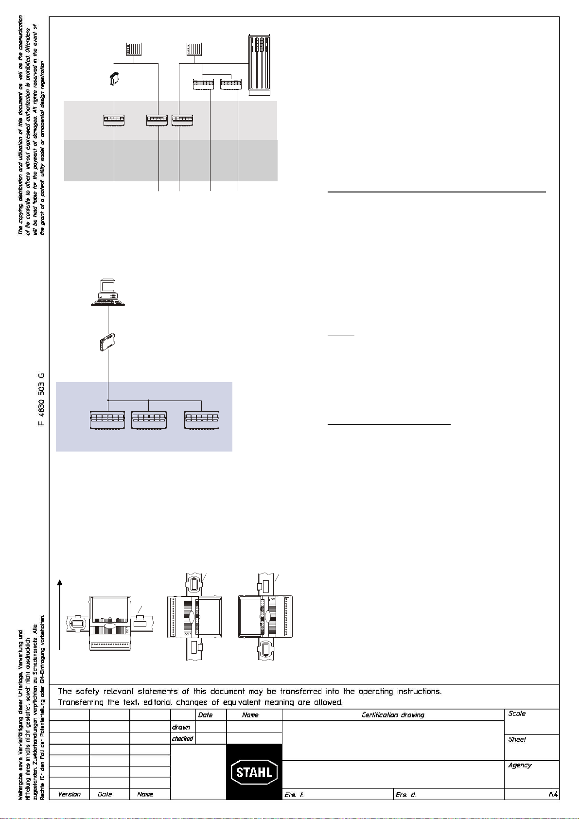
IS1 resp. IS1+ Remote I/O System
for CL I, DIV 2 / Zone 2
Overview
DCS
PLC
RS 485
nonicendive fieldbus
Nonhazardous
Location
Division 2
Zone 2
Division 1
Zone 1
Control Room
Division 1
Zone 0
Fieldbus Isolating
Repeater type
9185/12 Repeater /
Interface conector
Example: System Topology interfacing
Automation control systems with DIV 2 / Zone 2
Installation of IS1 resp. IS1+ Remote I/O System
Service Bus with Isolating Repeater interface
Mounting direction upwards:
The IS1 resp. IS1+ Remote I/O is a DIN rail mounted system designed
to record and output process control signals between hazardous
location transducers and sensors and a nonhazardous location
automation system. It consists of electrical apparatus in the
nonhazardous, Class I, Division 2 or Class I, Zone 2 hazardous
locations linked by either nonincendive field bus or a field bus installed
per the National Electrical Code, ANSI/NFPA 70 Article 500.
The nonincendive field bus circuit is achieved with the use of the
Fieldbus Isolating repeater type 9185. This device resides in the
nonhazardous location and provides a nonincendive field bus circuit
for connection to the IS1 resp. IS1+ Remote I/O System. See example
to the left.
The apparatus located in the Division 2 or Zone 2 hazardous location
are referred to as Remote I/O, and consist of the following major
subsystems.
1. CPU & Power Module or CPU Module, Power Module & Socket
The CPU & Power Module or the Power Module serves as a
power supply unit for its CPU unit or the CPU Module, as well as
for the supply to the I/O Modules and the field circuits. The power
supply to the I/O modules is implemented via the BusRail. For the
configuration with a redundant CPU and Power Module the power
supply to the I/O modules is decoupled with diodes. The power
supply unit has an under voltage monitoring circuit. The CPU
fulfils the function of a gateway between the internal bus of an IS1
field station and the fieldbus which connects the field station with
the automation system. The gateway is constructed as a dual
processor system. The I/O processor controls the data exchange
with the I/O modules and, when plugged-in, with the redundant
CPU & Power Module. The communication processor controls the
data exchange on the fieldbus and on the Service Bus.
2. BusRail
The BusRail provides a Power bus, an internal data bus and the
address lines for the interconnection of the CPU & Power Supply
to Remote I/O modules The Power bus distributes power supplied
by the CPU & Power Module to the I/O Modules plugged to the
BusRail. The communication with the I/O Modules is implemented
via the address and date bus lines. The interface of the CPU &
Power Module with the internal data bus on the BusRail is
designed with redundancy.
3. Components of Remote I/O System
All I/O Modules are manufactured in a unique DIN rail mount
package which then mounts onto the Remote I/O system BusRail.
All I/O Modules provide galvanic isolation between the field
circuits and the BusRail’s circuits.
4. Refer to pages 3 through 26 for information specific to each
module.
GENERAL NOTES:
1. Installation should be in accordance with Article 504/505 of the
National Electrical Code, ANSI/NFPA 70 and ANSI/ISA
RP12.06.01 resp. with the Canadian Electrical Code, Part I.
2. Use a general purpose enclosure meeting the requirements of
ANSI/ISA S82 for use in nonhazardous or Class I, Division 2
hazardous (Classified) Locations.
3. Use an FMRC Approved or NRTL listed Dust-ignition proof
enclosure appropriate for environment protection in Class II,
Division 1, Groups E, F and G; and Class III, hazardous
(Classified) Locations.
4. All I/O Modules may be detached from the BusRail or plugged
onto it during operation in hazardous areas.
5. The Modules may be operated in one of the three mounting
positions only.
I.S. 1 Wizard
Fieldbus Isolating
Repeater Type
9185/12
Nonincendive fieldbus
RS 232
1 2 18
. . .
Nonhazardous
Location
Division 2
Zone 2
RS 232 to RS 485
conversion
This is the PC software configuration
package used for commissioning, trouble-
shooting and MODBUS / HART configuration
BusRail
BusRail
BusRail

08.02. Reistle
2013
9400 6 031 002 1
none
FM
Kaiser
24 of 30
02 26.02.2014 Bagusch
01 17.02.2014 Bagusch
Nonhazardous
Class I, Division 2, Groups A, B, C, D or
Class I, Zone 2, Group IIC
Hazardous (Classified) Locations
The Digital Output Module Relay Type 9477/15-08-12 is an associated
electrical apparatus for use outside the hazardous area or in a Class I,
Division 2, Groups A, B, C, D or Class I, Zone 2, Group IIC Hazardous
(Classified) Location and is used to control up to eight Non-I.S. circuits
by means of relay contacts.
The internal system circuits are safely galvanically isolated from all
output circuits up to a peak voltage of 375 V.
Type 9477/15-08-12
Relay circuits may not exceed the following nominal values:
The output circuits are safely galvanically isolated from earth and from
each other up to an operating voltage of 250 V.
Connection allocation (X1)
Notes:
1. Suitable separation must be maintained between non I.S. wiring
of the relay circuits and I.S. wiring of the I/O modules and the I.S.
bus of the IS1 resp. IS1+ system. Use partition (SAP No. 162740)
for separation from I/O modules with I.S. circuits.
2. Do not disconnect Non-I.S. field wiring to X1 unless area is
known to be non-hazardous. Mechanically secure the terminal
blocks with the screws provided, to prevent from being detached
unintentionally.
3. Electrical Apparatus connected to an intrinsically safe system
must not use or generate voltages > 250 V (Umax).
4. Only use BusRail extension Type 9494/L1-V* fitted aside the
module. Do not mount the module fitted aside BusRail Begin or
BusRail Begin types 9494/A2-B0 or 9494/A2-E0.
5. General Notes (see Page 1)
WARNING: Substitution of components may impair Intrinsic Safety.
Do not disconnect equipment when a flammable or combustable atmosphere is present.
AVERTISSEMENT: Substitution de composants peut compromettre la sécurité intrinsèque.
Ne pas débrancher l’équipement en présence d’atmosphère inflammable ou combustible
U
n
250 V AC 30 V DC 110 V DC 220 V DC
I
n
2 A 2 A 0,3 A 0,12 A
P
n
100 VA - - -
Output Terminal
0
1
2
3
4
5
6
7
1, 2
3, 4
5, 6
7, 8
9, 10
11, 12
13, 14
15, 16
Digital Output Module Relay
Type 9477/15-08-12
Non I.S. terminals X1

F 4830 503
The copying, distribution and utilization of
t
h
i
s
d
o
c
u
m
e
n
t
a
s
w
e
l
l
a
s
t
h
e
c
o
m
m
u
n
i
c
a
t
i
o
n
of ist contents to others without expressed
a
u
t
h
o
r
i
z
a
t
i
o
n
i
s
p
r
o
h
i
b
i
t
e
d
.
O
f
f
e
n
d
e
r
s
w
i
l
l
be held liable for the payment of damages
.
A
l
l
r
i
g
h
t
s
r
e
s
e
r
v
e
d
i
n
t
h
e
e
v
e
n
t
o
f
t
h
e
g
r
a
n
t
of a patent, utility model or ornamental de
s
i
g
n
r
e
g
i
s
t
r
a
t
i
o
n
.
Weitergabe sowie Vervielfältigung dieses Dokuments, Verwertung und Mitteilung
seines Inhalts sind verboten, soweit nicht ausdrücklich gestattet. Zuwider-
handlungen verpflichten zu Schadenersatz. Alle Rechte für den Fall der Patent-,
Gebrauchsmuster- oder Geschmacksmustereintrag vorbehalten.
Certification drawing
April Toby
2004
94 006 02 31 2
none
CSA
Kaiser
A 17.08.09 Einsiedler
14 of 16
Nonhazardous or
Class I, Zone 2, Group IIC/IIB
Hazardous (Classified) Locations
The Digital Output Module Relay Type 9477/15-08-12 is an associated
electrical apparatus for use outside the hazardous area or in a Class I,
Zone 2, Group IIC/IIB Hazardous (Classified) Location and is used to
control up to eight Non-I.S. circuits by means of relay contacts.
The internal system circuits are safely galvanically isolated from all output
circuits up to a peak voltage of 375 V.
Type 9477/15-08-12
Relay circuits may not exceed the following nominal values:
U
n
250 V AC 30 V DC 110 V DC 220 V DC
I
n
2 A 2 A 0.3 A 0.12 A
P
n
100 VA - - -
The output circuits are safely galvanically isolated from earth and from
each other up to an operating voltage of 250 V.
Connection allocation (X1)
Output Terminal
0
1
2
3
4
5
6
7
1, 2
3, 4
5, 6
7, 8
9, 10
11, 12
13, 14
15, 16
Notes:
1.) Suitable separation must be maintained between Non I.S. wiring of
the relay circuits and I.S. wiring of the I/O modules and the I.S. bus of
the IS1 system.
2.) Do not disconnect Non I.S. field wiring to X1 or unplug module unless
area is known to be non-hazardous.
3.) Non I.S. wiring to the X1 terminals must meet the wiring requirements
of the Canadian Electrical Code, Part 1.
IS
1; Digital Output Module Relay
Type 9477/15-08-12
Non I.S. terminals X1
Table of contents
Languages:
Other Stahl Relay manuals


