Stahl ISPAC 9172 11 00 Series User manual


2
Inhaltsverzeichnis
1Allgemeine Angaben................................................................................................... 3
1.1 Hersteller.............................................................................................................3
1.2 Angaben zu Betriebsanleitung .............................................................................3
2Verwendete Symbole.................................................................................................. 3
3Sicherheitshinweise .................................................................................................... 3
4Normenkonformität...................................................................................................... 4
5Funktion...................................................................................................................... 5
6Kennzeichnung und technische Daten ........................................................................ 5
7Geräteaufbau..............................................................................................................6
8Anordnung und Montage............................................................................................. 6
8.1 Maßzeichnung ..................................................................................................... 6
8.2 Installation............................................................................................................6
8.3 Montage und Demontage..................................................................................... 7
9Inbetriebnahme........................................................................................................... 9
9.1 Anschlüsse ..........................................................................................................9
9.2 Einstellungen....................................................................................................... 9
10 Betrieb- und Betriebszustände.................................................................................. 10
11 Reparatur und Instandhaltung................................................................................... 10
12 Zubehör und Ersatzteile............................................................................................ 10
Content
1General information................................................................................................... 11
1.1 Manufacturer...................................................................................................... 11
2Symbols used........................................................................................................... 11
3Safety instructions..................................................................................................... 11
4Conformity to standards............................................................................................ 12
5Function.................................................................................................................... 12
6Marking and technical data ....................................................................................... 13
7Device description..................................................................................................... 14
8Arrangement and fitting............................................................................................. 14
8.1 Dimensions........................................................................................................ 14
8.2 Installation.......................................................................................................... 14
8.3 Mounting and dismounting................................................................................. 15
9Commissioning ......................................................................................................... 17
9.1 Connections....................................................................................................... 17
9.2 Settings.............................................................................................................. 17
10 Operation and operational states .............................................................................. 18
11 Maintenance and repair ............................................................................................ 18
12 Accessories and spare parts..................................................................................... 18
EG-Konformitätserklärung / EC-Declaration of Conformity............................................... 19
Certification drawing –FM................................................................................................ 20
Certification drawing - CSA.............................................................................................. 21
deutsch Betriebsanleitung
Ex i Relaismodul Typ 9172 3
1 Allgemeine Angaben
1.1 Hersteller
1.2 Angaben zu Betriebsanleitung
ID-Nr. 160372 / 9172601310
Dokumenten Nr. S-BA-9172-003-de/en-01/2013
HW Revision B
2 Verwendete Symbole
!
Sicherheitshinweise, die unbedingt beachtet werden müssen.
Bei Sicherheitshinweisen auf dem Gerät sind die entsprechenden Angaben
bzw. Sicherheitshinweise der Betriebsanleitung zu beachten!
c
Das Produkt erfüllt die anwendbaren EG-Vorschriften.
e
Die so gekennzeichneten Stromkreise sind, entsprechend der jeweiligen
Kennzeichnung, für explosionsgefährdete Bereiche zugelassen.
Symbol für Eingang
Symbol für Ausgang
Hinweiszeichen: Beschreibt Hinweise und Empfehlungen.
3 Sicherheitshinweise
In diesem Kapitel sind die wichtigsten Sicherheitsmaßnahmen zusammengefasst. Es
ergänzt die entsprechenden Vorschriften, zu deren Studium das verantwortliche Personal
verpflichtet ist.
Bei Arbeiten in explosionsgefährdeten Bereichen hängt die Sicherheit von Personen und
Anlagen von der Einhaltung aller relevanten Sicherheitsvorschriften ab. Das Montage- und
Wartungspersonal trägt deshalb eine besondere Verantwortung. Die Voraussetzung dafür
ist die genaue Kenntnis der geltenden Vorschriften und Bestimmungen.
Bei Errichtung und Betrieb ist Folgendes zu beachten:
Es gelten die nationalen Montage- und Errichtungsvorschriften (z.B. EN 60079-14).
Bei SIL Anwendungen FMEDA Report SIL STAHL 04/04-03 R006 beachten.
Das Gerät ist in Zone 2, Zone 22 oder außerhalb explosionsgefährdeter Bereiche zu
installieren.
Bei Einsatz in Zone 2 und Zone 22 ist das Gerät in ein Gehäuse einzubauen, das den
Anforderungen der EN 60079-15 genügt.
R. STAHL Schaltgeräte GmbH
Telefon: +49 7942 943-0
Am Bahnhof 30
Fax: +49 7942 943-4333
74638 Waldenburg
Internet: www.stahl.de
Germany

Betriebsanleitung deutsch
4Ex i Relaismodul Typ 9172
Bei Einsatz in Zone 2 oder 22 dürfen an die eigensicheren Ausgangsstromkreise
eigensichere Geräte der Zonen 1, 0, 21 und 20 angeschlossen werden.
Das Gerät darf nur an Geräte angeschlossen werden, in denen keine höheren
Spannungen als AC 253 V (50 Hz) auftreten können.
Bei Einsatz in Zone 2 und Zone 22 dürfen die Kontakte an maximal 125 V AC/DC
angeschlossen werden.
Stellen sie sicher, dass die an die Kontakte angeschlossenen Stromkreise der
Überspannungskategorie I/II/ III gemäß IEC 60664-1 entsprechen.
Die sicherheitstechnischen Werte der / des angeschlossenen Feldgeräte/s müssen mit
den Angaben des Datenblattes bzw. der EG-Baumusterprüfbescheinigung
übereinstimmen.
Die Sicherheitshinweise dieser Betriebsanleitung
Beschädigungen können den Explosionsschutz aufheben.
Verwenden Sie das Gerät bestimmungsgemäß, nur für den zugelassenen Einsatzzweck
(siehe „Funktion“).
!Warnung
Durch fehlerhaften oder unzulässigen Einsatz sowie das Nichtbeachten der Hinweise
dieser Betriebsanleitung kann der vorgesehene Schutz beeinträchtigt werden, die
Gewährleistung unsererseits wird in diesen Fällen ausgeschlossen.
Umbauten und Veränderungen am Gerät, die den Explosionsschutz
beeinträchtigen, sind nicht gestattet.
Das Gerät darf nur in unbeschädigtem, trockenem und sauberem Zustand
eingebaut und betrieben werden.
Sollten Sie Fragen bezüglich der richtigen Handhabung des Gerätes haben, wenden Sie
sich bitte an R. STAHL Schaltgeräte GmbH, Am Bahnhof 30, 74638 Waldenburg,
Germany, Telefon +49-7942-943-0 wenden oder an eine unserer Niederlassungen, siehe
www.stahl-ex.com.
4 Normenkonformität
Bitte entnehmen sie die Normenkonformität der EG-Konformitätserklärung im Anhang
dieses Dokumentes.
Die aktuelle EG-Baumusterprüfbescheinigung können Sie im Internet unter www.stahl.de
herunterladen.
deutsch Betriebsanleitung
Ex i Relaismodul Typ 9172 5
5 Funktion
Die Ex i Relaismodule dienen zur Trennung von eigensicheren und nicht eigensicheren
Stromkreisen bzw. verschiedenen eigensicheren Stromkreisen. Je nach Ausführung wird
entweder die Ansteuerung oder der Kontaktausgang bzw. Ansteuerung und Kontakt-
ausgang über einen eigensicheren Stromkreis betrieben.
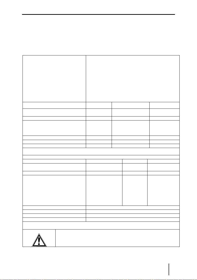
6 Kennzeichnung und technische Daten
Typbezeichnung
CE-Kennzeichnung
ATEX-Kennzeichnung Explosionsschutz
und
Prüfstelle und Bescheinigungsnummer
IECEx Kennzeichnung Explosionsschutz
Bescheinigungsnummer
Umgebungstemperaturbereich
9172/**-11-00
c0158
eII 3(1) G Ex nA nC [ia Ga] IIC T4 Gc
eII (1) D [Ex ia Da] IIIC
BVS 04 ATEX E 097 X
Ex nA nC [ia Ga] IIC T4 Gc and [Ex ia Da] IIIC
IECEx BVS 09.0002X
-20 °C … +70 °C
(Siehe Kapitel 8)
Sicherheitstechnische Daten
9172/*0-11-00
9172/*1-11-00
9172/*2-11-00
Ansteuerung
max. Spannung / max. Strom, Ui / Ii
30 V / 150 mA
-
30 V / 150 mA
max. Leistung, Pi
1,3 W
-
1,3 W
Kontakte
max. Spannung / max. Strom, Ui / Ii
-
125 V AC / 4 A
125 V DC / 0,25 A
60 V DC / 0,3 A
30 V DC / 4 A
125 V AC / 4 A
125 V DC / 0,25 A
60 V DC / 0,3 A
30 V DC / 4 A
max. Leistung, Pi
-
100 VA
100 VA
innere Kapazität, Ci/ Induktivität, Li
vernachlässigbar
vernachlässigbar
vernachlässigbar
Isolationsspannung Um
253 VAC
253 VAC
-
Weitere Angaben und Wertekombinationen siehe EG-Baumusterprüfbescheinigung
Technische Daten (Auszug aus dem Datenblatt)
Spulenstromkreis
Ansteuerspannung UN
Ex i:
12...30 V DC
12...31,2 V DC
Ex i:
12...30 V DC
Stromaufnahme bei 12 V
< 16 mA
< 16 mA
< 16 mA
Kontaktstromkreis (Wechsler)
Maximale Belastung DC *)
Maximale Belastung AC *)
*) bei Zone 2 Installation max. 125 V AC/DC
220 V / 0,1 A
125 V / 0,25 A
60 V / 0,3 A
250 V / 0,4 A / 100 VA
125 V / 0,8 A / 100 VA
30 V / 3,3 A / 100 VA
Ex i:
125 V / 0,25 A
60 V / 0,3 A
30 V / 4 A
125 V / 4 A
Ex i:
125 V / 0,25 A
60 V / 0,3 A
30 V / 4 A
125 V / 4 A
Umgebungsbedingungen
Betriebstemperatur
-20...+70 °C
Lagertemperatur
-40...+80 °C
relative Feuchte (keine Betauung)
< 95 %
Weitere technische Daten sind dem aktuellen Datenblatt zu entnehmen.
Bei anderen vom Standard abweichenden Betriebsbedingungen nehmen Sie bitte
Rücksprache mit dem Hersteller.

Betriebsanleitung deutsch
6Ex i Relaismodul Typ 9172
7 Geräteaufbau
#
Beschreibung
1
Schwarze Klemme
Anschlussklemmen für den sicheren
Bereich
9
Blaue Klemme
Anschlussklemmen für den Ex-
Bereich
16
LED „OUT1“, gelb
Ausgang Kanal 1 aktiviert.
17
LED „OUT2“, gelb
Ausgang Kanal 2 aktiviert.
8 Anordnung und Montage
8.1 Maßzeichnung
8.2 Installation
Die Geräte sind außerhalb explosionsgefährdeter Bereiche zu installieren.
Die Geräte sind auch für den Betrieb in explosionsgefährdeten Bereichen der Zone 2 und
Zone 22 zugelassen. Sie sind hierbei in ein Gehäuse einzubauen, das den Anforderungen
der IEC/EN 60079-15 genügt (z.B. Gehäuse 8146 der R. STAHL Schaltgeräte GmbH).
Maß X
Schraubklemmen
108 mm
Federzugklemmen
128 mm
deutsch Betriebsanleitung
Ex i Relaismodul Typ 9172 7
8.3 Montage und Demontage
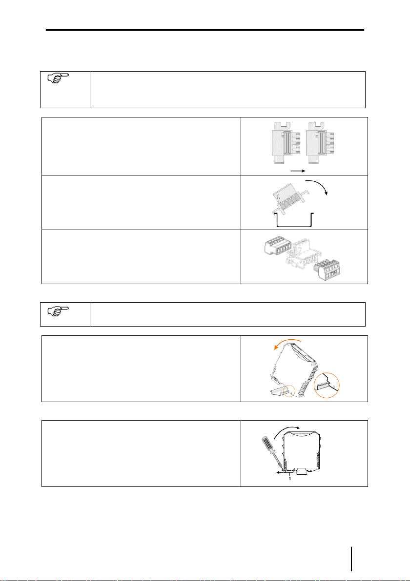
9.3.1 Montage / Demontage pac-Bus
Der pac-Bus ist ein Zubehör, dass die Verdrahtung der Hilfsenergie und das
Auslesen der Sammelfehlermeldung vereinfacht.
Die Komponenten für den pac-Bus Typ 9194 müssen separat bestellt
werden.
Gewünschte Anzahl der pac-Bus-Elemente
zusammenstecken.
pac-Bus-Elemente auf Hutschiene aufrasten.
Klemmenset am Anfang und am Ende
einstecken.
pac-Bus ist montiert.
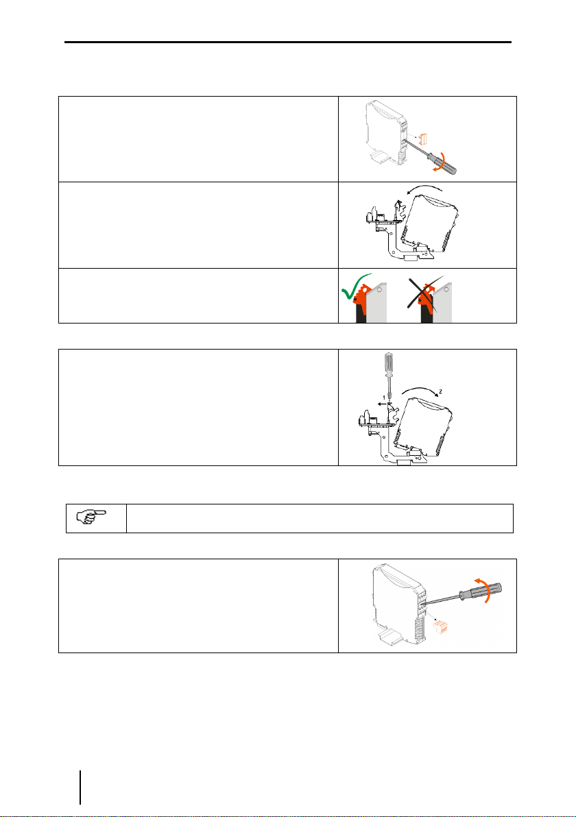
9.3.2 Montage / Demontage auf Hutschiene
Montage
Beim Aufschwenken des Geräts auf die Hutschiene darauf achten, dass es
nicht verkantet.
Gerät an die Hutschiene ansetzen. Die
Aussparung des Gehäuses muss dabei auf die
Außenkante der Hutschiene gesetzt werden.
Gerät auf Hutschiene aufrasten.
Demontage
Fußriegel (1) mit dem Schraubendreher etwas
herausziehen.
Gerät herausschwenken.
Betriebsanleitung deutsch
8Ex i Relaismodul Typ 9172
9.3.3 Montage / Demontage auf pac-Träger
Montage
Schwarze und grüne Klemmen entfernen.
Bei einkanaligen Geräten: Abdeckung im
Klemmenschacht 2 entfernen (zwischen
schwarzer und grüner Klemme)
Gerät auf pac-Träger aufsetzen. Die Aussparung
des Gehäuses muss dabei auf die Außenkante
des pac-Trägers gesetzt werden. Danach das
Gerät einschwenken bis roter Rasthebel
einrastet.
Der rote Rasthebel muss eingerastet sein.
Demontage
Rasthebel (1) mit einem Schraubendreher
ausschwenken.
Gerät wird aus dem Steckplatz geschoben (2).
9.3.4Montage / Demontage abziehbare Klemmen
Alle Geräte sind mit abziehbaren Klemmen ausgestattet.
Demontage
Schraubendreher hinter Klemme ansetzen.
Klemme herausdrücken.
Montage
Klemme in Gerät stecken, bis Klemme einrastet.

deutsch Betriebsanleitung
Ex i Relaismodul Typ 9172 9
9 Inbetriebnahme
9.1 Anschlüsse
Typen 9172/*0-11-00
Typen 9172/*1-11-00
Typen 9172/*2-11-00
9.2 Einstellungen
Keine
1+
6-
5+
2-
10
11
Hazardous area
1
2
1
2
Sicherer Bereich
Safe area
14
15
Ex-Bereich
12
13
1
3
4
6
5
2
10+
11-
Hazardous area
1
2
1
2
Sicherer Bereich
Safe area
14+
15-
Ex-Bereich
1+
6-
5+
2-
10
11
Hazardousarea Hazardousarea
1
2
1
2
14
15
Ex-Bereich Ex-Bereich
12
13

Betriebsanleitung deutsch
10 Ex i Relaismodul Typ 9172
10 Betrieb- und Betriebszustände
Bevor Sie das Gerät in Betrieb nehmen, stellen Sie sicher, dass
das Gerät vorschriftsmäßig installiert wurde
das Gerät nicht beschädigt ist
die Kabel ordnungsgemäß angeschlossen sind
11 Reparatur und Instandhaltung
Es wird empfohlen, Reparaturen an unseren Geräten ausschließlich durch uns durchführen
zu lassen. In Ausnahmefällen kann die Reparatur auch durch eine andere, zugelassene
Stelle erfolgen.
Die Geräte sind wartungsfrei.
Führen die beschriebenen Vorgehensweisen nicht zum gewünschten Erfolg, wenden Sie
sich bitte an unsere nächste Vertriebsniederlassung. Zur schnellen Bearbeitung benötigt
diese von Ihnen folgende Angaben:
Typ und Seriennummer,
Kaufdaten,
Fehlerbeschreibung,
Einsatzzweck (insbesondere Eingangs-/Ausgangsbeschaltung)
12 Zubehör und Ersatzteile
Verwenden Sie nur Original-Zubehör sowie Original-Ersatzteile der R. STAHL
Schaltgeräte GmbH.
english Operating Instructions
I.S. Relay Module Type 9172 11
1 General information
1.1 Manufacturer
Information regarding the operating instruction:
ID-Nr. 160372 / 9172601310
Document number S-BA-9172-004-de/en-11/2012
Hardware revision B
2 Symbols used
3 Safety instructions
The most important safety instructions are summarised in this chapter. It is intended to
supplement the relevant regulations which must be studied by the personnel responsible.
When working in hazardous areas, the safety of personnel and plant depends on
complying with all relevant safety regulations. Assembly and maintenance staff working on
installations therefore have a particular responsibility. The precondition for this is an
accurate knowledge of the applicable regulations and provisions.
When installing and operating the device, the following are to be observed:
The national installation and assembly regulations (e.g. EN 60079-14) apply.
For SIL applications please observe the FMEDA report “SIL STAHL 04/04-03 R006”.
The devices may be installed in Zone 2, Zone 22 or outside the explosion hazard areas.
If installed in Zone 2 and 22, the device has to be mounted in an enclosure that meets
the requirements of EN 60079-15.
R. STAHL Schaltgeräte GmbH
Phone: +49 7942 943-0
Am Bahnhof 30
Fax: +49 7942 943-4333
74638 Waldenburg
Internet: www.stahl.de
Germany
!
Safety note, which is essential to take note.
With safety note on the equipment the appropriate data and/or safety reference
of the manual are to be considered!
c
The device complies with the applicable EC standards.
e
Electric circuits marked with the symbol are certified, according to the respective
marking, for hazardous locations.
Symbol for input
Symbol for output
Information sign: Provides a note or recommendation.
Operating Instructions english
12 I.S. Relay Module Type 9172
When used in Zone 2 or 22, intrinsically safe devices of Zones 1, 0, 21 and 20 may be
connected to the intrinsically safe contact or coil circuits.
The I.S. relay modules may only be connected which will not be subjected to voltages
higher than AC 253 V (50 Hz).
When used in Zone 2 and Zone 22 the maximum voltage at the contacts may not exceed
125 V AC/DC
Please ensure that the devices which are connected to the contacts of the relay module
are compliant to surge category III / II / I acc. to IEC 60664-1.
The safe maximum values of the connected field device(s) must correspond to the values
of the data sheet or the EC-type examination certificate.
The safety guidelines in these operating instructions
Any damage can invalidate the explosion protection.
Use the device in accordance with the regulations and for its intended purpose only (see
“Function”).
!Warning
With incorrect or unauthorized use or non-compliance with these instructions the
intended protection can be impaired, the warranty provision is invalidate on our part in
these cases.
oNo changes to the devices or components impairing their explosion protection are
permitted.
oFurthermore, the device may only be operated if it is undamaged, dry and clean.
Should there be any question about the correct handling of the module, please contact R.
STAHL Schaltgeräte GmbH, Am Bahnhof 30, 74638 Waldenburg, Germany, telephone
+49-7942-943-0, or contact one of our offices or representatives see www.stahl-ex.com.
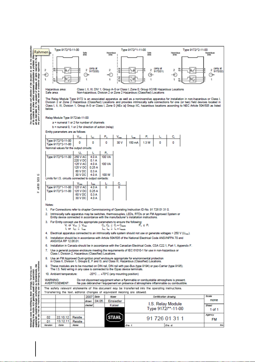
4 Conformity to standards
The information about the conformity to standards can be found in the manufacturer’s
declaration of conformity in the appendix of this document.
The current EC-Type Examination Certificate can be downloaded from the Internet
www.stahl-ex.com .
5 Function
The I.S. relay modules are used for the galvanic isolation of intrinsically safe and none
intrinsically safe circuits or the galvanic isolation of two intrinsically safe circuits. Depending
on the version either the control circuit and/or the contact output is operated via an
intrinsically safe circuit.
english Operating Instructions
I.S. Relay Module Type 9172 13
6 Marking and technical data
Type designation
CE marking
ATEX marking explosion protection
and
Testing authority and certificate number
IECEX marking explosion protection
Certificate number
Ambient temperature range
9172/**-11-00
c0158
eII 3 (1) G Ex nA nC [ia Ga] IIC T4 Gc
eII (1) D [Ex ia Da] IIIC
BVS 04 ATEX E 097 X
Ex nA nC [ia Ga] IIC T4 Gc and [Ex ia Da] IIIC
IECEx BVS 09.0002X
-20 °C … +70 °C
(See chapter 8)
Safety data
9172/*0-11-00
9172/*1-11-00
9172/*2-11-00
Coil circuit
max. voltage / max. current, Ui / Ii
30 V / 150 mA
-
30 V / 150 mA
max. power, Pi
1,3 W
-
1,3 W
Contacts
max. voltage / max. current, Ui / Ii
-
125 V AC / 4 A
125 V DC / 0,25
A
60 V DC / 0,3 A
30 V DC / 4 A
125 V AC / 4 A
125 V DC / 0,25
A
60 V DC / 0,3 A
30 V DC / 4 A
max. power, Pi
-
100 VA
100 VA
internal capacity, Ci/ inductance, Li
negligible
negligible
negligible
Insulation voltage Um
253 VAC
253 VAC
-
See EC-type examination certificate for further information and value combinations
Technical data (extract from the data sheet)
Coil circuit
Control voltage UN
Ex i:
12...30 V DC
12...31,2 V DC
Ex i:
12...30 V DC
Current consumption at 12 V
< 20 mA
< 20 mA
< 20 mA
Contact circuit (changeover)
Maximum load DC *)
Maximum load AC *)
*) If installed in Zone 2 / Div. 2 max. 125 V AC/DC
220 V / 0,1 A
125 V / 0,25 A
60 V / 0,3 A
250 V / 0,4 A / 100 VA
125 V / 0,8 A / 100 VA
30 V / 3,3 A / 100 VA
Ex i:
125 V / 0,25 A
60 V / 0,3 A
30 V / 4 A
125 V / 4 A
Ex i:
125 V / 0,25 A
60 V / 0,3 A
30 V / 4 A
125 V / 4 A
Ambient conditions
Operating temperature
-20...+70 °C
Storage temperature
-40...+80 °C
Relative humidity (no condensation)
< 95 %
Additional technical data can be found in the current data sheet. (www.stahl.de)
Please consult the manufacturer before operating under conditions which deviate from
the standard operating conditions.

Operating Instructions english
14 I.S. Relay Module Type 9172
7 Device description
#
Description
1
Black terminals
Connection terminals for the safe area
9
Blue terminals
Connection terminals for the
hazardous area (intrinsic safe).
16
LED „OUT1“, amber
Output channel 1 activated.
17
LED „OUT2“, amber
Output channel 1 activated.
8 Arrangement and fitting
8.1 Dimensions
8.2 Installation
The device may be installed in Zone 2, Zone 22 or outside of the hazardous area.
In the case of operation in Zone 2 or Zone 22, the apparatus must be fitted in an enclosure
which complies with the requirements of IEC/EN 60079-15 (e.g. in an enclosure type 8146
from the R. STAHL Schaltgeräte GmbH company).
Size X
Screw terminals
108 mm
Spring clamp terminals
128 mm

english Operating Instructions
I.S. Relay Module Type 9172 15
8.3 Mounting and dismounting
9.3.1 Mounting of pac-Bus
The pac-Bus is an accessory, which facilitates the wiring of the power
supply and the common fault signalization.
The components of the pac-Bus type 9194 need to be ordered separately.
Assemble the required number of pac-Bus
elements.
Snap the pac-Bus segment on the DIN rail.
Assemble the terminal set at the beginning and
the end of the pac-Bus segment.
9.3.2 Mounting / Dismounting on DIN rail with or without pac-Bus
Mounting
Take care that the devices is not canted before it is snapped on the DIN rail.
Put the device on the DIN rail. Take care that the cut out of
the enclosure fits onto the edge of the DIN rail.
Swivel the device until it is snapped on the DIN rail.
Dismounting
Pull the latch (1) with the screw driver out.
Swivel the device out.

Operating Instructions english
16 I.S. Relay Module Type 9172
9.3.3 Mounting / Dismounting on pac-Carrier
Mounting
Dismount the black and the green terminal. (see chapter
9.3.4)
Single channel device: Dismount the cover of terminal slot 2.
(between black and green terminal)
Put the device on the pac-Carrier and swivel the device until
the red locking handle is locked.
Please check that the locking handle is locked.
Dismounting
Put the screw driver into the red locking handle (1) and move
the screw driver into the described direction.
Device will be moved out of the slot (2).
9.3.4 Mounting / Dismounting detachable terminals
All devices are equipped with detachable terminals.
Dismounting
Place the screw driver between terminal and
enclosure.
Move the screw driver as described.
Mounting
Place the terminal into the terminal slot and press it towards the device until it is locked.

english Operating Instructions
I.S. Relay Module Type 9172 17
9 Commissioning
9.1 Connections
Types 9172/*0-11-00
Types 9172/*1-11-00
Types 9172/*2-11-00
9.2 Settings
None
1+
6-
5+
2-
10
11
Hazardous area
1
2
1
2
Sicherer Bereich
Safe area
14
15
Ex-Bereich
12
13
1
3
4
6
5
2
10+
11-
Hazardous area
1
2
1
2
Sicherer Bereich
Safe area
14+
15-
Ex-Bereich
1+
6-
5+
2-
10
11
Hazardousarea Hazardousarea
1
2
1
2
14
15
Ex-Bereich Ex-Bereich
12
13

Operating Instructions english
18 I.S. Relay Module Type 9172
10 Operation and operational states
Before commissioning the device, please ensure that:
the device has been installed in accordance with the standards
the device is not damaged
the cables are properly connected
11 Maintenance and repair
It is recommended that all repairs to our devices be carried out by R. Stahl. In exceptional
cases, repair may be performed by approved third-parties.
The devices are maintenance-free.
If the procedure described above does not obtain the desired result, please contact your
local R. STAHL sales and service representative. In order to quickly process your request,
please provide us with the following information:
Type and serial number,
Purchase date(s),
Description of the error,
Application description (particularly the configuration of the
input/output circuitry)
12 Accessories and spare parts
Use only original accessories and spare parts from R. STAHL Schaltgeräte GmbH.

19
EG-Konformitätserklärung / EC-Declaration of Conformity
20
Certification drawing –FM
This manual suits for next models
4
Table of contents
Languages:
Other Stahl Relay manuals


