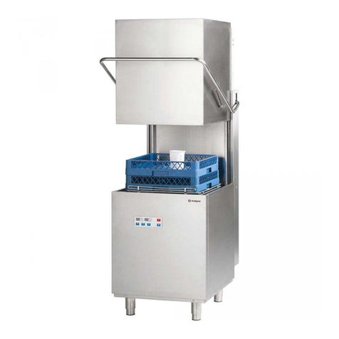
Stalgast 801400 User manual

DISHWASHER
supply voltage
230 v
Model: 801400, 801401, 801555, 801556,
801565, 801566
supply voltage
230/400 v
Model: 801505, 801506, 801507, 801515,
801516, 801517
INSTRUCTION MANUAL
STALGAST Radom sp. z o.o. ul. Staniewicka 5 03-310 Warsaw
v1.0 - 07.2016

- 2 -
TABLE OF CONTENTS
1. SAFETY INSTRUCTIONS ..........................................................................................................3
2. PURPOSE OF THE DEVICE .......................................................................................................3
3. TECHNICAL DATA .....................................................................................................................4
4. INSTALLATION ..........................................................................................................................5
4.1. Positioning of the device ........................................................................................................................................ 5
4.2. Connection to the power supply source............................................................................................................... 5
4.3. Connection of the device to the water and sewerage system............................................................................. 6
4.4. Drain hole............................................................................................................................................................... 6
4.5. The rst start-up.................................................................................................................................................... 7
5. HEALTH & SAFETY RULES........................................................................................................7
6. DEVICE OPERATION .................................................................................................................8
6.1. Activities carried out before the start of washing................................................................................................ 8
6.2. Loading of the dishwasher..................................................................................................................................... 8
6.3. Manual elements.................................................................................................................................................... 8
6.4. Electronic elements ............................................................................................................................................. 10
7. PROBLEMS, CAUSES, SOLUTIONS .......................................................................................13
8. MAINTENANCE .......................................................................................................................14
9. PACKAGING, LOADING AND TRANSPORT ........................................................................15
10. LIST OF SPARE PARTS ............................................................................................................16
11. ELECTRICAL WIRING DIAGRAM ...........................................................................................18
11.1. Electrical wiring diagram for dishwasher 801400, 801401................................................................................ 18
11. 2 .
Electrical wiring diagram for dishwasher
GE313, GE323, GE333, GE343, GE353, GE363.............................. 19
11. 3 . Electrical wiring diagram for dishwasher GE413, GE423, GE433, GE443........................................................ 20
12. DISPOSING OF USED EQUIPMENT.......................................................................................21
13. WARRANTY..............................................................................................................................21

- 3 -
Thank you for purchasing our product. Please carefully read this instruction manual before rst use.
Reproduction of this manual without the consent of the manufacturer is prohibited.
The photos and drawings are illustrative and may differ from the purchased device.
CAUTION: The manual should be kept in a safe place, available to the staff.
The manufacturer reserves the right to change the technical parameters of the device without prior notice.
1. SAFETY INSTRUCTIONS
Failure to follow this instruction may cause life-threatening situations.
• CAUTION: If the device was damaged during transport it should not be connected!
•In the case of a longer break in the operation of the device (night breaks, holiday breaks, etc.) it is necessary to disconnect
the device from the electrical power supply.
•Incorrect operation and improper use can cause serious damage to the device or injuries to persons.
•The device should only be used for the purpose for which it was designed.
•The manufacturer assumes no liability for any damages caused by incorrect operation and improper use of the device.
•During operation the device and the power cable plug must be protected against contact with water or other liquids. If the
device is accidentally fell into water or was ooded with water, it is necessary to immediately pull out the plug from the
socket, and then commission the inspection of the device to an expert technician.
•Do not insert any objects into the openings in the housing of the device.
•Do not touch the power cord plug with wet hands.
•Regularly inspect the condition of the plug and the power cord. In the case any damage to the plug or the cable is found, it
should be repaired in an authorized repair point.
•In case the device falls or is damaged in any other way, before further use it is always necessary for it to be inspected and
possibly repaired at a specialized repair point.
•Never open the housing of the device by yourself.
•Never try to repair the device by yourself – it could lead to life-threatening situations.
•It is prohibited for any changes and repairs to be performed by persons who are not professionally trained.
•Protect the power supply cable from contact with sharp or hot objects and keep it away from open ames.
•When disconnecting the device from the power supply socket, switch off the device rst. Always grab it by the plug and
never pull by the cord.
•Secure the power cable to ensure that no one pulls it from the socket by mistake and that no one trips over the cable.
• If the power cord is damaged, it has to be replaced. Non-detachable power supply cords should be replaced at
a specialized repair workshop or by a qualied person.
•Control the operation of the device during use.
•Do not allow for the device to be used by minors, people with physical or mental disabilities and people with impaired mo-
bility, as well as persons without the appropriate experience and knowledge regarding the proper use of the device. Such
persons can operate the device only under the supervision of a person responsible for safety.
•If the device is not currently in use or is cleaned, it is necessary to always unplug it from the power source by removing the
plug from the socket.
• CAUTION: If the plug of the power cord is connected to the electrical socket, the device remains energized.
•Never pull the device by the power cord.
•Do not move the dishwasher holding by the door handle.
2. PURPOSE OF THE DEVICE
The dishwasher is exclusively intended for professional use and should be operated by trained personnel. The device is
intended for washing and sanitizing dishes (plates, bowls, cups, cutlery, trays, etc.) and other similar items used in the catering
industry and related branches, in compliance with the international regulations and standards relating to safety conditions in
the eld of electrical engineering, mechanics and electromagnetic compatibility.
- 4 -
3. TECHNICAL DATA
Model 801400,
801401
801505, 801506,
801507, 801515,
801516, 801517
801555, 801556, 801565, 801566
Dimensions (LxWxH) 465x565x700 565x665x835
Power Supply 230 V/l 230V/l 400V/3+N+PE 400V/3+N+PE
Frequency 50 Hz
Maximum Energy Consumption 2730 W 3400 W 4900 W 6650 W
Supply water pressure 200-400 kPa
Supply water temperature 10-55°C
Hardness of water in the water
network
5-6 dH
Water consumption 2,4 l/cycle 2,5 l/cycle 2,5 l/cycle
Boiler capacity 2,5 l 5,5 l 6,5 l
Tank capacity 14 l 26 l 26 l
Standard cycle duration 120/180 sec. 120/180 sec. 90/120/180 sec.
Noise level 64 dB(A)
Protection IPX3
Net weight 30 kg 58 kg 58 kg
Power cord type H07RN-F 3x1.5mm2 with
plug
3x2.5mm2 5x1.5mm2 5x1.5mm2
Wash water temperature 60 -65°C (140-149°F)
Rinse water temperature 82-90°C (181-194°F)
The dishwasher has an automatic sanitization function (it is an integral part of the washing cycle).
Fig.1
1. Control panel
2. Dishwasher door
3. Bottom panel
4. Adjustable feet
5. Chamber
6. Drain hose
7. Water connection
8. Terminal box
9. Nameplate
10. Connection giagram label

- 5 -
4. INSTALLATION
4.1. Positioning of the device
The device should be moved to the place of installation, unpacked and the package contents should be checked. In the even
any damage to the device or any of its elements is detected, this must be immediately notied to the transport company.
The packaging material must be kept away from children and pets, as they may cause an accident. All materials used for the
packaging of the device are environment-friendly and can be safely stored in an appropriate place.
Items intended for recycling are marked as follows:
•PE – polyethylene: external packaging, manual cover, protective packaging,
•PP – polypropylene: handles,
•PS – polystyrene foam: edge protection, package cover.
•Wooden and cardboard elements of the device should be left in places intended for this purpose in accordance with the
applicable laws.
It is prohibited to store the elements of the device and the device itself directly in the natural environment. The device is made
of stainless steel and the elements which can be easily removed. The plastic components of the device are marked with an
appropriate symbol.
All connections to the device must meet the standards applicable in the place of installation. The manufacturer is not
liable for any injuries or damage to the product resulting from failure to comply with the standards applicable in the place of
installation. Before installing the device, it is necessary to make sure that the moisture-sensitive elements are properly secured
against getting wet, e.g. during the cleaning of the device. The device should be placed in the desired location and then the
protective packaging should be removed. The device should be leveled using a spirit level and four adjustable legs in order to
ensure its stability. Any other way of leveling the device should be approved by the manufacturer.
4.2. Connection to the power supply source
The device’s connection to the electrical network may only be executed by the employees of the technical service or a person
with appropriate licenses in accordance with the applicable laws. The electrical parameters of the device were included in the
table in point 3. It is prohibited to execute one electrical protection for two devices. It is necessary to install an external safety
switch and a residual-current circuit breaker.
Both switches must be installed in a quickly and easily accessible place in such a way, that they guarantee the disconnection of
the device from the electric power source in accordance with category II.
The power cord connected to the terminal box with and appropriate plug is NOT supplied with the device and must be
purchased separately.
Conditions for connection to the electrical installation:
•Check whether the voltage in the power supply network is consistent with the voltage indicated on the nameplate of the
device.
•Manual devices (801505, 801506, 801507, 801515, 801516, 801517) that are designed for connection of the power supply
to the terminal box, can be connected in two ways in accordance with the diagram placed on the label (g. 2) located on
the back of the device. A standard connection is made for a 400V power supply. The type of the cord (g. 3) is given in
table in point 3.

- 6 -
L1, L2, L3 - remaining colors
PE - yellow-green
N - blue
Fig. 2 - Etikette mit dem Schaltplan Fig. 3 - The power cord
Fig. 4 – 1. Connection diagram panel; 2. Terminal box; 3. Nameplate
The power cord should be a exible, oil resistant cable with a protective conductor, with a polychloroprene
sheath – code mark 60745 IEC 57. It may be prepared by the manufacturer and available from him, or in
specialized repair workshops!
4.3. Connection of the device to the water and sewerage system
The water pipes and the electric supply cable extend from the back side of the device. The water supply pipe should be
connected to a ¾’’ outlet. Only a new pipe can be used for the execution of the connection. In order to ensure secure
operation, the value of water pressure should be between 2-4 bar. If the pressure is higher, it is necessary to install a pressure
regulator. The main valve should be installed over the pipe feeding water to the device. The main valve should be installed in
an easily accessible place; for this reason, it should not be installed behind the device. The cycle duration was given for the feed
water temperature of 50°C. In the event the device is connected to cold water, the cycle duration time may increase, because
the device is equipped with a constant temperature pressure rinse system.
4.4. Drain hole
The device is equipped with a drain pipe which should be installed at oor level with the use of an air vent.
Before starting the device, make sure that the supply pipe and the drain pipe were not bent, jammed or otherwise
damaged during installation.
1
2
3

- 7 -
4.5. The rst start-up
Before starting the machine, check the correct operation of the electrical protection system. The above steps and the
rst start-up of the device may only be performed by the employees of the technical service, who will also conduct a brief
training concerning the functioning of the device. Each device is equipped with an adjustable rinse aid dispenser. Meanwhile,
only select models of the device are equipped with a detergent dispenser with the possibility of adjustment. The detergent and
rinse aid containers should be placed in the proper location and then the suction tubes should be connected: the clear tube to
the detergent and the blue tube to the rinse aid. For adjustment, use the adjustment screws shown in g. 5. It is recommended
for the adjustment to be performed by the personnel of the company supplying the rinse aid and detergent. Before connecting
the suction tubes it is necessary to attach weights (in order to keep the tubes on the bottom of the containers) and put on the
lters ( g. 6).
Fig. 5 Fig.6
In the event the dispensers have not been installed before the installation of the device, it can be done at a later time using an
appropriate set of tools.
Alternatively, an external detergent dispenser may be connected through an electric connection using a 2x0,5mm H07 RN-F
electric cable. The cable should be connected through the passage indicated on the technical data diagram, in accordance
with the electrical parameters of the device and the applicable legal provisions. Dispenser parameters: 230V/50Hz, 8W. The
detergent dispenser should be connected to the dishwasher using a clear tube.
5. HEALTH & SAFETY RULES
In order to prevent burns and electric shock please observe the following safety rules:
•training of staff in the use of the device in accordance with the information contained in this instruction manual
•training of the personnel in the scope of the basic principles of operation of electrical appliances, workplace safety and
provision of rst aid in case of need,
•before starting any maintenance work, disconnect the device from the power supply,
•it is prohibited to turn the device on, if any heating element and/or control element is damaged.
The manufacturer is not liable for any injuries or damage to the product resulting from failure to comply with the
recommendations contained in the instruction manual, improper use of the device, use of non-original spare parts and
attempts to repair the device independently.
•The device should be connected to an electrical grid with grounding in accordance with the applicable regulations and
standards.
•The device complies with the standards introduced under the European Union’s Directives. The proper storage of the
device is an element of prevention of the pollution of the environment.
Do not add solvents such as alcohol or turpentine to the dishwasher as they can cause an explosion. It is also prohibited
to place dishes with remnants of food products in the dishwasher.
The dishwasher and its components should never be used as a ladder or as a support for other devices or items.
Do not sit or lean against the open door of the dishwasher as that may lead to an accident. In order to avoid the above
situation, the doors of the device should always be closed.
The water remaining in the dishes after the completion of the cycle is not suitable for drinking.
The device may not be independently operated by minors or persons with limited intellectual, physical and sensory
abilities, who are not able to fully comply with the rules contained in this manual. The above mentioned persons may only
operate the device under supervision.

- 8 -
6. DEVICE OPERATION
6.1. Activities carried out before the start of washing
Only use detergents and rinse aids intended exclusively for industrial dishwashers. It is prohibited to use detergents intended
for manual dish washing. We recommend using detergents produced specically for this dishwasher.
When lling the detergent containers, be careful not to accidentally activate the device, as this may cause damage or
failure of the device. It is prohibited to mix various detergents, as this may cause damage to the dispenser. Industrial detergents
may cause irritation. Therefore it is always necessary to follow the instructions provided on the detergent packaging.
The valve
should be
opened
Check: The main switch should be turned
off; the “OFF” sign will appear on
the display.
The levels of detergent and rinse aid in
the containers
The correctness of
the lters placement,
the correctness of the
nozzle rotation, the
throughput of the device
(whether there are any
foreign bodies inside the
device which prevent
the correct operation of
the device).
6.2. Loading of the dishwasher
1. Plates
The basket can hold 12 deep plates or 18 at plates. It is necessary to remove remnants of food from the surface of the plates.
Before washing plates with dried up remnants of cheese, eggs, etc., they should be left in cold water in order to soak off.
Fig. 7 Fig.8
2. Glassware
It is necessary to remove any residue from glasses, wine glasses, etc., and place them in the basket with the bottom facing up.
3. Cutlery
Use the basket to washing cutlery. It is recommended that cutlery is placed with the handles facing down. Knives and forks
must be handled with appropriate care (risk of injury).
6.3. Manual elements
1. Control panel

- 9 -
2. Button functions
On/Off Program selection
Wash cycle Lamp indicating chamber heating element operation
Lamp indicating boiler heating element operation
3. Start-up of the device
Turn on the switch located on the wall, open the dishwasher door, place the overow plug in the appropriate place (g. 9) and
close the door of the device. Press the On/Off button (g. 10). After the tank and the boiler are lled with water the boiler
heating element lamp will light up (bottom, g. 13). After the heating of water in the boiler is completed, the dishwasher
chamber water heating cycle will begin – the chamber heating element lamp will light up (top, g. 13). Insert the basket into
the device chamber and wait until the indicator light of the chamber heating element turns off. Before starting the wash
cycle, it is necessary to select the program. Program 2 (120 s.) is the default program. After pressing the program selection
button we will switch to Program 3 (180 s.), which will be signaled by a ashing lamp (g. 12), In order to start the wash cycle,
press the button (g. 11). After starting the wash cycle, the indicator lamp will light up. If the door is opened during the wash
cycle, the program stops automatically. After the door is closed, the program continues the wash cycle. After the program is
completed, the wash cycle indicator lamp turns off, and the boiler heating element lamp lights up. Remove the basket from the
device chamber.
Fig. 9 Fig. 10 Fi g. 11 Fig. 12 Fig. 13
4. Emptying of the tank in models equipped with a drain pump
Turn the device off by pressing the On/Off switch (g. 9), then open the door of the device, remove the overow plug and
close the door. The draining process proceeds automatically until the tank is completely emptied of water. In order to
reactivate the device, put the overow plug back in its place, close the door and press the On/Off switch. However, if the
device will not be used any more, turn the main switch off.
5. Emptying of the tank in models not equipped with a drain pump
Turn the device off by pressing the switch (g. 9), then open the door of the device, remove the overow plug (g. 8) and wait
until the water is drained off completely from the tank. Put the overow plug back in its place, close the door of the device.

- 10 -
Do not turn the device off when the water is still in the tank. Before turning the device off, always empty the tank
of water. In the event the device will no longer be used, after the completion of the above and the possible initiation of a
regeneration cycle, it is necessary to turn the device off by pressing the switch. The main switch should then be turned off and
the water valve should be closed.
6.4. Electronic elements
1. Control panel
2. Button functions
Start button - turns the device on
Set button - conrmation of the introduced input
data, setting of the password
- access to data setting: P1, P2, P3, P4,
P5, P6
Down arrow - reduces the washing or rinsing
temperature
- drain pump (optional)
Up arrow - increases the washing or rinsing
temperature and increases the
duration of the wash or rinse cycle. C1-
90 sec. C2-120 sec. C3-180 sec.
Stop button - turns the device off (does not
disconnect the device from power
supply, the complete disconnection
of the device occurs after the plug is
removed from the socket or the main
external switch is turned off), stops the
washing and rinsing process
Display 1 Display 2 Dishwasher activation
Dishwasher deactivation

- 11 -
3. Displays
- display 1 – indicates the rinsing and sanitization temperature; washing cycle length C1 – C2 – C3.
- display 2 – indicates the washing temperature.
4. Parameter setting
After the rst pressing of the display will show
. Use the arrows to change the
data on display 2 into:
. This is the factory-set password.
a. programming of temperatures and times
CUSTOMER SETTINGS
Press . again. The displays will show the following data:
- sanitization-rinsing temperature (70-
95oC)
The arrows can be used to adjust the temperature on display 2.
Press again. The displays will show the following data:
- washing water temperature (40-70oC).
The arrows can be used to adjust the temperature on display 2.
SERVICE SETTINGS (it is recommended that they are not changed)
Press again.The displays will show the following data: - minimal sanitization temperature (50-
90oC).
The arrows can be used to adjust the temperature on display 2.
Press again. The displays will show the following data:
- time for water release after the
activation of the pressure switch (0-40 sec.) determining the water level.
The arrows can be used to adjust the time of water release on display 2.
Press again.The displays will show the following data:
- sanitization time (8-15 sec.).
The arrows can be used to adjust the sanitization time on display 2.

- 12 -
During the setting of the above parameters the display screen is blinking, and the values of the parameters can be changed
using the arrows.
RECOMMENDED SETTINGS
Function Name Function description Recommended value
P1 sanitization (rinsing) temperature 90ºC
P2 washing temperature 60ºC
P3 minimal sanitization temperature 82ºC
P4 time for water release after the activation of
the pressure switch
20 seconds (for pressure of 2 bar)
P5 sanitization (rinsing) time 15 seconds
b. programming of cycle duration
Press
Display 1 will indicate:
– the set time is 90 seconds
– the set time is 120 seconds;
– the set time is 180 seconds;
The program is exited automatically 5 seconds after the selection of the desired cycle duration
5. Table of errors
Error code Error description
EP 1 lling time exceeded, but a second attempt was undertaken
EP 2 double lling time exceeded, attempts terminated
E1 LO temperature of probe T1 is too low (below 0°C) (or an open circuit in the probe)
E1 HI temperature of probe T1 is too high (above 110°C) (or a short circuit in the probe)
E2 LO temperature of probe T2 is too low (below 0°C) (or an open circuit in the probe)
E2 HI temperature of probe T2 is too high (above 110°C) (or a short circuit in the probe)
E3 LO temperature of probe T3 is too low (below 0°C) (or an open circuit in the probe)
E3 HI temperature of probe T3 is too high (above 110°C) (or a short circuit in the probe)
E4 power outage during the operation of the dishwasher
Et boiler overheating
E1 temperature difference between probe T1 and T2 is too high (>30°C)
E2 safety temperature exceeded – error displayed after the completion of emergency rinsing
6. Start-up of the device
Turn on the switch located on the wall, open the dishwasher door, place the overow plug in the appropriate place (g. 9)
and close the door of the device. Press the switch button . After the tank and the boiler are lled with water, the boiler
heating element will start operation. After the heating of water in the boiler is completed, the dishwasher chamber water
heating cycle will begin. Insert the basket into the device chamber and wait until the water in the chamber reaches the set
temperature. Before starting the wash cycle, it is necessary to select the program. The wash cycle is activated automatically
by opening and closing the dishwasher door. If the door is opened during the wash cycle, the program stops automatically.
After the door is closed, the program continues the wash cycle. The completion of the wash cycle program is indicated by a
sound signal from the control board. Remove the basket from the device chamber.

- 13 -
Water for washing 60 -65°C (140-149°F)
Water for rinsing/sanitizing 82-90°C (181-194°F)
7. Emptying of the tank in models equipped with a drain pump
Turn the device off by pressing the switch , then open the door of the device, remove the overow plug and close
the door. Turn the drain pump on using the button . The draining process proceeds automatically until the tank
is completely emptied of water. In order to reactivate the device, put the overow plug back in its place, close the door and
press the On/Off switch. However, if the device will not be used any more, turn the main switch off.
8. Emptying of the tank in models not equipped with a drain pump
Turn the device off by pressing the the switch , then open the door of the device, remove the overow plug and wait
until the water is drained off completely from the tank. Put the overow plug back in its place, close the door of the device.
Do not turn the device off when the water is still in the tank. Before turning the device off, always empty the tank
of water. In the event the device will no longer be used, after the completion of the above and the possible initiation of a
regeneration cycle, it is necessary to turn the device off by pressing the switch. The main switch should then be turned off and
the water valve should be closed.
7. PROBLEMS, CAUSES, SOLUTIONS
Note: If the activities for the removal of the faults described in the table below did not provide the desired result, please
contact the repair service (qualied technical personnel).
PROBLEM CAUSE SOLUTION
The device does not turn on The doors of the device are not closed
properly
Open and then close the door again
Blown fuse Replace the fuse (call the service)
Improper connection to the electrical
network
Check the connection to the electrical
network
Washing process lasts too long Wash water temperature is not
correct
Set the correct temperature
Incorrect water level in the chamber
of the device
Clean the water inlet lter
The device does not wash dishes Broken washing pump Call the service
Low pump pressure Clean the pump lter
Water temperature too low Adjust the water heating time
Incorrect washing agent Contact the manufacturer
Arms covered with lime scale or the
presence of foreign bodies
Clean the arms and remove the
foreign bodies
Empty detergent container Fill the container
Faults in the water treatment device Kontakt mit Service
Spots on forks, glasses and vessels Incorrect arrangement of the dishes Arrange the dishes in accordance with
the instructions
Rinse water temperature is too high Set the correct temperature
Incorrect water pressure Clean the lters
Water hardness level is too high Check the water hardness
The detergent did not work, because
of dirty water in the device
Change the water in the device
Incorrect drying of the dishes Change the water in the device
Incorrect rinse agent Contact the manufacturer

- 14 -
Dishwasher does not rinse
Contaminated water inlet lter Clean the lter
Low water pressure Clean the pump lter and the solenoid
valve
Broken rinse pump Call the service
Leaking solenoid valve Contamination of the solenoid valve Call the service
Note: during the installation of the
device foreign bodies or unwanted
chemical compounds from the water
supply could have contaminated the
solenoid valve.
The water pressure in the device is
too low
Contaminated water inlet or solenoid
valve lter
Clean the water inlet or solenoid valve
lter
Low hardness of water in the water
network
Contact a plumber
The pump is not pumping out water Clogged pump Contact the service
Faulty pump
8. MAINTENANCE
Before starting any maintenance work, disconnect the device from the power supply.
Daily maintenance involves the removal of all items from the chamber and washing it using a cloth dampened in water with a
dish washing liquid and then wiping dry with a clean cloth. It is prohibited to wash the device under running water and to use
pressure washers for this purpose.
In case of intensive use of the device, it is recommended that the lters are cleaned every 30-40 washing cycles, in order to
ensure the proper functioning of the device. For this purpose it is necessary to partially empty the tank of water.
The lters should be removed and it must be ensured that the greasy deposits and food remnants do not fall into the opening
under the lters. The lters must be cleaned from the remnants of food and sediments and then abundantly rinsed. Do not use
sharp tools or sharp edges to clean the lters. Make sure that the lime scale deposits are also removed, as that prevents their
accumulation on the surface of the lter.
The surfaces of the lters should be thoroughly cleaned with a damp cloth using neutral (non-caustic) detergents which do not
contain chlorine and agents causing corrosion and mechanical damage to stainless steel surfaces.
In order to avoid the creation of corrosive stains on the stainless steel surfaces, avoid the use of caustic detergents containing
chlorine and agents that cause corrosion and mechanical damage to the stainless steel surface. Do not use detergents causing
damage to stainless steel for cleaning the oor and the immediate surroundings of the device.

- 15 -
Once a month, please check whether:
•all the electrical connections are executed properly
•all the components of the device are working properly
•it is necessary to remove the nozzles (g. 14) (lower and upper 2, 6) by unscrewing the screws (4, 3). It is necessary to
unscrew the caps (7) located at the both ends of the nozzles.
Fig. 14
•The external surface of the device should be cleaned using soap and a damp cloth and should then be thoroughly rinsed
and wiped dry.
In order to ensure the proper operation of liquid dispensers it is recommended that the tubes are replaced every 6 months.
At least once a year the device should be inspected in order to check the degree of wear and to identify possible faults of
the components and parts of the device. In case any faults are detected, they have to be removed by a qualied technical
personnel (technical service). The technical service should pay particular attention to:
•the condition of the heating elements
•the condition of the electrical installation
•the condition of the heating elements protections
•the degree of wear of the device
Although a special program of periodic device inspections has not been developed, it is recommended that the correct
operation of the device and its security features are veried by the technical service two times per year. Any possible damage
or failure of the device caused by the user’s non-compliance with the guidelines contained in this manual, as well as their failure
to comply with the applicable laws and standards, will not be treated as a liability of the manufacturer.
Breaks in the operation of the device
If it is expected that the device will not be used for a longer period of time, it is necessary to empty the containers for the
detergent and the rinse aid in order to prevent their crystallization and the resulting pump damage. In connection with the
above, it is necessary to remove the suction tubes from both containers and place them in a bowl lled with clean water, carry
out several washing cycles and then empty the tank of water. Finally, the main switch should be turned off and the water valve
should be closed. The suction tubes should be reconnected to the containers only once the device is used again (the clear tube
to the detergent container and the clear tube with a blue cover to the rinse aid container).
It is prohibited to leave an activated device and an open water valve for a longer period of downtime in the device
operation.
9. PACKAGING, LOADING AND TRANSPORT
The washer is packaged in accordance with the applicable standards. The loading of the device onto means of transport and
the unloading should be carried out using appropriate lifting equipment and trucks. The devices should be transported on
covered means of transport. During transportation the washer should be protected against movement, strong shock and
other mechanical damage.

- 16 -
10. LIST OF SPARE PARTS
NO. PART NAME INDEX
801400
801401
801505
801506
801507
801515
801516
801517
801555
801556
801565
801566
1Boiler 6000 W M72136 - - - - - - - - 1 1 1 1
2Boiler 4500 W PPB0150 - - 1 1 1 1 1 1 - - - -
3Boiler 2600 W M72105 1 1 - - - - - - - - -
4Power supply cable M70686 1 1 - - - - - - - - - -
5Peristaltic pump for the rinse aid M72252 111111111111
6Peristaltic pump for detergent M72087 1 1 - 1 1 - 1 1 1 1 1 1
72-channel solenoid valve M72009 111111111111
8Fuse holder M72051 111111111111
9Magnetic sensor M90820 1 1 1 1 1 1 1 1 1 1 1 1
10 Magnet M90816 111111111111
11 Dishwasher pump M72050 - - 1 1 1 1 1 1 1 1 1 1
12 Dishwasher pump M72123 1 1 - - - - - - - - - -
13 Pressure switch M72054 111111111111
14 Chamber heating element M72059 - - 1 1 1 1 1 1 1 1 1 1
15 Chamber heating element M72126 1 1 - - - - - - - - - -
16 Drain pump M72124 - 1 - - 1 - - 1 - 1 - 1
17 Drain pump connecting hose M72255 - - - - 1 - - 1 - 1 - 1
18 Water drain hose M72077 1 - 1 1 - 1 1 - 1 - 1 -
19 Water drain hose M72134 - 1 - - 1 - - 1 - 1 - 1
20 Contactor 5.5 kW M70145 - - 1 1 1 1 1 1 2 2 2 2
21 Contactor 7.5 kW M90339 - - - - - - - - 1 1 1 1
22 Transformer 230 V / 10 V M90466 - - - - - - - - 1 1 1 1
23 Control board M71075 - - - - - - - - 1 1 1 1
24 Executive board M71074 - - - - - - - - 1 1 1 1
25 Three-phase interference
suppression lter
M72083 - - 1 1 1 1 1 1 1 1 1 1
26 Single-phase interference
suppression lter
M72014 1 1 - - - - - - - - - -
27 6 position terminal block M72037 - - 1 1 1 1 1 1 1 1 1 1
28 3 position terminal block M7 2118 1 1 - - - - - - - - - -
29 1 position terminal block M72038 111111111111
30 Main switch M72028 1 1 1 1 1 1 1 1 - - - -
31 Program switch M72055 1 1 1 1 1 1 1 1 - - - -
32 Switch button M91002 3 3 3 3 3 3 3 3 - - - -
33 Switch frame M91003 3 3 3 3 3 3 3 3 - - - -
34 Green indicator light M72094 1 1 1 1 1 1 1 1 - - - -
35 Blue indicator light M72095 4 4 4 4 4 4 4 4 - - - -
36 Power supply indicator light M72096 1 1 1 1 1 1 1 1 - - - -
37 Wash cycle indicator light M72097 2 2 2 2 2 2 2 2 - - - -
38 Boiler, chamber indicator light M72098 2 2 2 2 2 2 2 2 - - - -
39 Thermostat 90ºC M72065 1 1 1 1 1 1 1 1 - - - -
40 Chamber thermostat 55°C M72067 1 1 1 1 1 1 1 1 - - - -
41 Control board M72092 1 1 1 1 1 1 1 1 - - - -
42 Cable gland M90145 1 1 - - - - - - - - - -
43 Foot M72049 444444444444
44 Drain plug M72072 - - 1 1 1 1 1 1 1 1 1 1
45 Drain plug M72132 1-----------

- 17 -
46 Drain plug M72133 - 1 - - - - - - - - - -
47 Drain lter M72015 - - 1 1 1 1 1 1 1 1 1 1
48 Door lock M72061 111111111111
49 Water t-connector M72057 111111111111
50 Water t-connector – rinse aid
pump
M72056 111111111111
51 Rinse arm M72024 - - 2 2 2 2 2 2 2 2 2 2
52 Wash arm M72023 - - 2 2 2 2 2 2 2 2 2 2
53 Rinse arm M7 2113 2 2 - - - - - - - - - -
54 Wash arm M72112 1 1 - - - - - - - - - -
55 Wash arm feed pipe M72076 - - 1 1 1 1 1 1 1 1 1 1
56 Water supply hose M72073 111111111111
57 Rinse pump M72091 - - - - - 1 1 1 - - 1 1
58 Temperature sensor M71056 - - - - - - - - 3 3 3 3
59 Terminal box M70533 - - 1 1 1 1 1 1 1 1 1 1
60 Drain gasket M72025 - - 1 1 1 1 1 1 1 1 1 1
61 Pressure switch housing gasket M72026 - - 1 1 1 1 1 1 1 1 1 1
62 Pressure switch housing gasket M7 2116 1 1 - - - - - - - - - -
63 Impeller gasket M72027 2 2 - - - - - - - - - -
64 Pump gasket M7 2114 1 1 - - - - - - - - - -
65 Rinse arm gasket M72227 1 1 - - - - - - - - - -
66 Dishwasher pump o-ring M72121 1 1 - - - - - - - - - -
67 Conductor M72030 111111112222
68 Water pump connector hose M72033 - - 1 1 1 1 1 1 1 1 1 1
69 Hose connecting the pump and
the impeller
M72034 - - 1 1 1 1 1 1 1 1 1 1
70 Drain lter M72109 1 1 - - - - - - - - - -
71 External drain lter M7 2110 1 1 - - - - - - - - - -
72 Door handle M72256 - - 1 1 1 1 1 1 1 1 1 1
73 Door handle M72257 1 1 - - - - - - - - - -
74 Universal basket 400 M90551 1 1 - - - - - - - - - -
75 Cup for cutlery M72088 111111111111
76 Basket for plates 810301 - - 1 1 1 1 1 1 1 1 1 1
77 Basket for cutlery 810101 - - 1 1 1 1 1 1 1 1 1 1
78 Basket for glassware 810501 - - 1 1 1 1 1 1 1 1 1 1

- 18 -
11. ELECTRICAL WIRING DIAGRAM
11.1. Electrical wiring diagram for dishwasher 801400, 801401
PD - washing liquid pump
PZ - drain pump
PN - rinsing pump
PL - linear pump
L.K. - chamber heater indicator
light
L.Led - LED indicator light
L.C. - washing time indicator
light
L.Z. power supply indicator
light
L.B. - boiler indicator light
E - electrovalve
Chamber heater
Thermostat
Pressure sensor
Boiler
Program switch
Programme switch-off
Magnetic switch-off
Branching cube
Control board
Fuse
Main switch-off
Condensator

- 19 -
11. 2 .
Electrical wiring diagram for dishwasher
GE313, GE323, GE333, GE343, GE353, GE363
PWP - rinsing booster pump
DPM - washing liquid pump
PZ - drain pump
PN - rinsing pump
PL - linear pump
L.K. - chamber heater indicator
light
L.Led - LED indicator light
L.C. - washing time indicator
light
L.Z. power supply indicator
light
L.B. - boiler indicator light
E - electrovalve
Condensator
Programme
switch
Programme switch-off
Magnetic switch-off
Chamber heater
Thermostat
Main switch-off
Control board
Branching cube
Pressure sensor
Fuse
Boiler
KAD Box
Power strip
Contactor

- 20 -
11. 3 . Electrical wiring diagram for dishwasher GE413, GE423, GE433, GE443
Chamber heater
Boiler
Cube
Rinsing
pump
Washing
liquid
pump
Drain pump
Water pump
Electrovalve
Drain pump
KAD Box
Fuse
Electric terminal
Contactor P
Contactor K
Contactor K
Condensator
Pressure
sensor
Transformer
Micro switch-o
Probes
Control panel
Boiler
Boiler
Chamber
Control board
This manual suits for next models
11
Table of contents
Other Stalgast Dishwasher manuals

Stalgast
Stalgast 803020 User manual

Stalgast
Stalgast 803021 User manual

Stalgast
Stalgast 801350 User manual

Stalgast
Stalgast 801005 User manual

Stalgast
Stalgast 804350 User manual

Stalgast
Stalgast 803025 User manual

Stalgast
Stalgast 801350V03 User manual

Stalgast
Stalgast 804420 User manual

Stalgast
Stalgast 801350V06 User manual