Stamina Inmotions User manual

45-1002
STAMINA PRODUCTS
MADE IN CHINA
Product May Vary Slightly
From Pictured.
2005, 12
Exercise can present a health
risk. Consult a physician
before beginninganyexercise
program with this equipment.
If you feel faint or dizzy,
immediately discontinue use
of this equipment. Serious
bodily injury can occur if this
equipment is not assembled
and used correctly. Serious
bodily injury can also occur if
all instructions are not
followed. Keep others and
pets away from equipment
when in use. Always make
sure all bolts and nuts are
tightened prior to each use.
Followallsafety instructionsin
this manual.
When calling for parts or
service, please specify the
following number.
WARNING
CAUTION:
Weight on this product should not exceed 250 lbs.
2040 N. Alliance, Springfield, MO 65803
Customer Service Number
1 (800) 375-7520
www.staminaproducts.com
This Product is Produced Exclusively by
Owner's
Manual
2005 Stamina Products, Inc.

TABLE OF CONTENTS
SAFETY INSTRUCTIONS
To reduce the risk of serious injury, read the following Safety Instructions before
using the InMotionTM II Treadmill.
WARNING:
Before starting any exercise or conditioning program you should consult with your personal
physician to see if you require a complete physical exam.This is especially important if you
are over the age of 35, have never exercised before, are pregnant, or suffer from any
illness. READ AND FOLLOW THE SAFETY PRECAUTIONS. FAILURE TO FOLLOW
THESE INSTRUCTIONS CAN RESULT IN SERIOUS BODILY INJURY.
WARNING:
2
1.
2.
3.
4.
5.
6.
7.
8.
9.
10.
11.
12.
13.
14.
15.
16.
17.
18.
Read all warnings posted on the InMotionTM II Treadmill.
Read this Owner's Manual and follow it carefully before using the InMotionTM II Treadmill. Make
sure that it is properly assembled and tightened before use.
We recommend that two people be available for assembly of this product.
Keep children away from the InMotionTM II Treadmill. Do not allow children to use or play on the
InMotionTM II Treadmill. Keep children and pets away from the InMotionTM II Treadmill when it is
in use.
It is recommended that you place this exercise equipment on an equipment mat.
Setupandoperatethe InMotionTM IITreadmill on asolidlevelsurface. Donotposition theInMotionTM
II Treadmill on loose rugs or uneven surfaces.
Inspect the InMotionTM II Treadmill for worn or loose components prior to use. Tighten/replace any
loose or worn components prior to using the InMotionTM II Treadmill.
Keep fingers clear of all pinch points when folding and unfolding the InMotionTM II Treadmill.
When folding the InMotionTM II Treadmill for storage, make sure that Base Frame Assembly is
locked securely in the folded position by the Spring Pin.
Consult a physician prior to commencing an exercise program. If, at any time during exercise, you
feel faint, dizzy, or experience pain, stop and consult your physician.
Follow your physician's recommendations in developing your own personal fitness program.
Always choose the workout which best fits your physical strength and flexibility level. Know your
limits and train within them. Always use common sense when exercising.
Do not wear loose or dangling clothing while using the InMotionTM II Treadmill.
Never exercise in bare feet or socks; always wear correct footwear, such as running, walking, or
crosstraining shoes. Be sure that they fit well, provide foot support and feature non-skid rubber soles.
Becarefultomaintain your balancewhileusing,mounting, dismounting, orassembling the InMotionTM
II Treadmill, loss of balance may result in a fall and serious bodily injury.
The InMotionTM II Treadmill should not be used by persons weighing over 250 pounds.
The InMotionTM II Treadmill should be used by only one person at a time.
The InMotionTM II Treadmill is for consumer use only. It is not for use in public or semipublic
facilities.
Safety Instructions 2
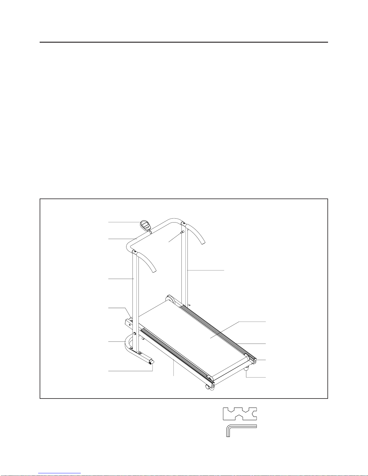
Before You Begin 4
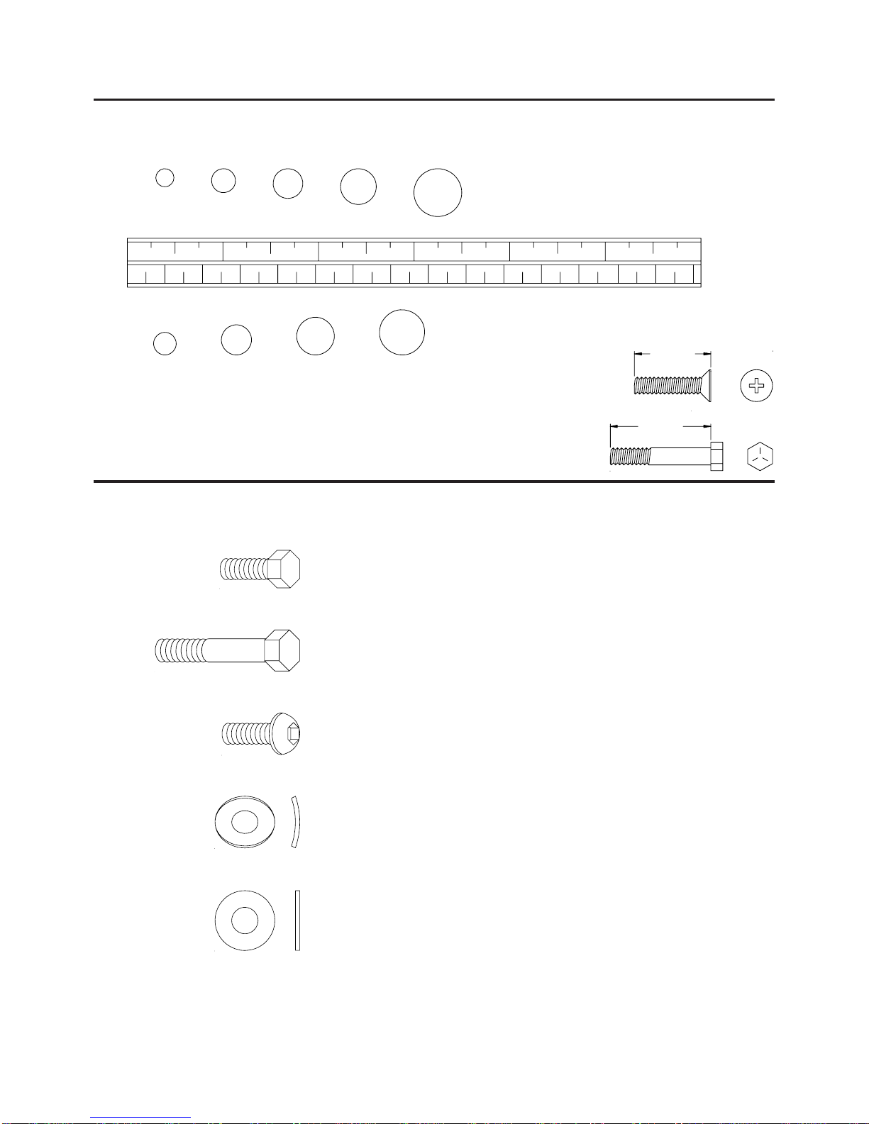
Hardware Illustrations 5
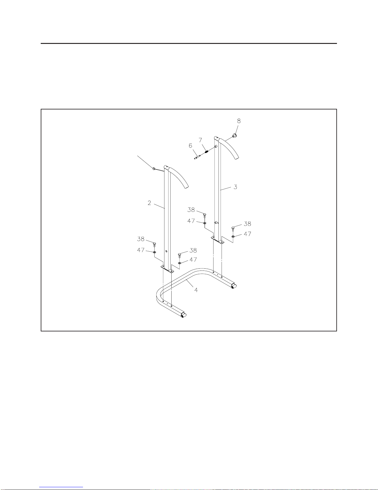
Assembly Instructions 6
Using The Electronics Meter 8
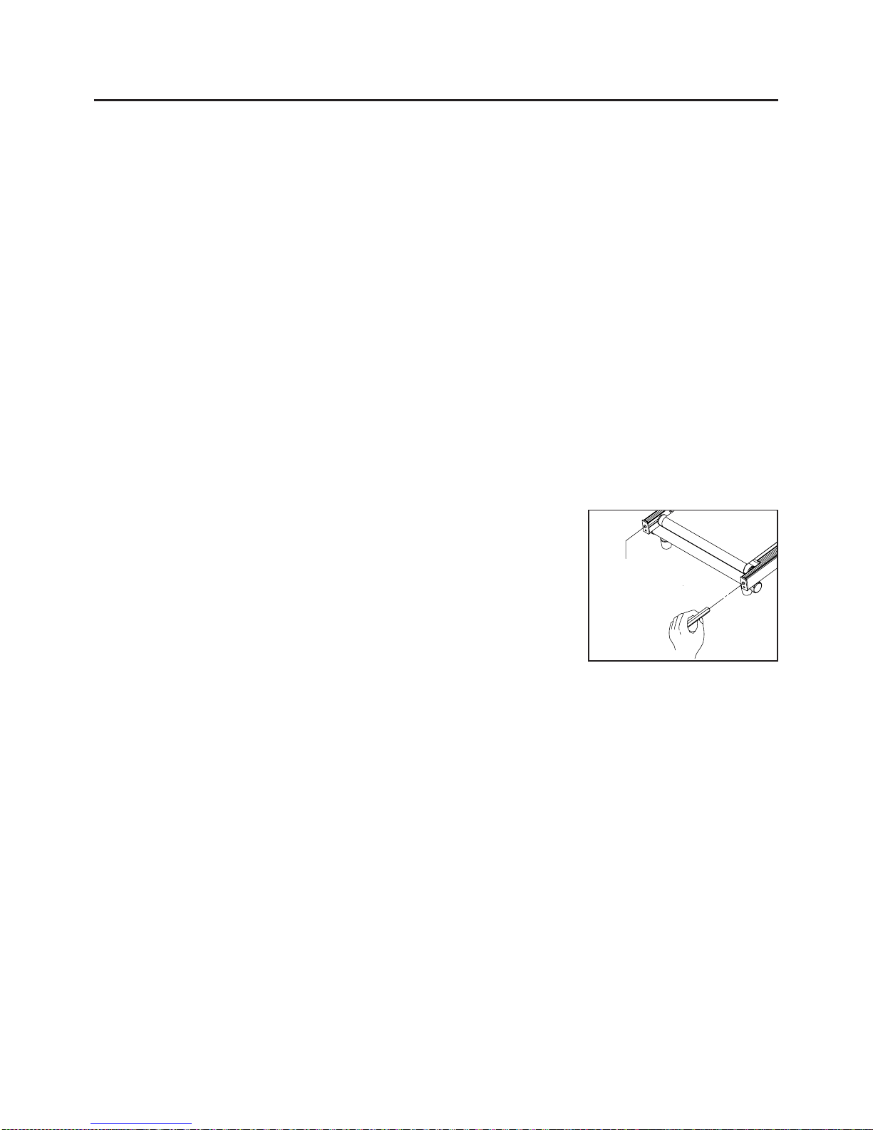
Treadmill Adjustments 9
Maintenance 10
Storage 11
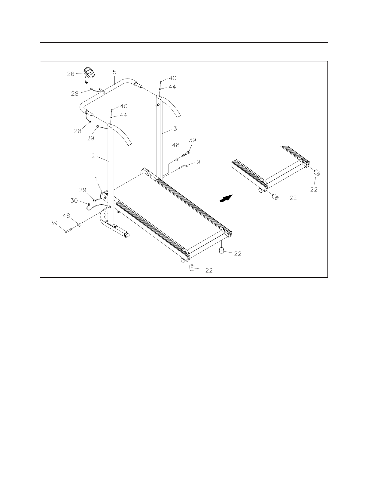
Product Parts Drawing 12
Parts List 13
Warranty 14
Fax/Mail Ordering Form 15
Page Page

THANK YOU FOR PURCHASING THE
InMotionTM II Treadmill
To help you get started, we have pre-assembled most of your
InMotionTM II Treadmill at the factory with the exception
of those few parts left unassembled for shipping purposes.
Simply follow the few assembly instructions set forth in this manual.
Within a few minutes you will be getting your body into shape and on your
way to achieving a happier and healthier lifestyle.
Should you have any questions,
please call our Customer Service Department toll-free number,
1 (800) 375-7520
Monday - Friday, 8:00 A.M. - 5:00 P.M., Central Time.
CALL US FIRST
3

BEFORE YOU BEGIN
Thank you for choosing the InMotionTM II
Treadmill. We take great pride in producing this
quality product and hope it will provide many hours
ofqualityexercise tomakeyou feelbetter,look better
and enjoy life to its fullest.
Yes, it's a proven fact that a regular exercise
program can improve your physical and mental
health. Too often, our busy lifestyles limit our time
and opportunity to exercise. The InMotionTM II
Treadmillprovidesaconvenientandsimplemethod
to begin your assault on getting your body in shape
and achieving a happier and healthier lifestyle.
Before reading further, please review the drawing
below and familiarize yourself with the parts that are
labeled.
Read this manual carefully before using the
InMotionTM II Treadmill.
Although Stamina tries to manufacture its products
with the finest materials and uses the highest
standards of manufacturing, occasionally a part that
does not fit, is the incorrect size, or is otherwise
inappropriate is found. Even with the highest
inspection and quality controls in place these things
will happen occasionally. Please do not return the
product. For your convenience, Stamina has a
Customer Service Department with a toll-free
number. If a part is missing, does not fit, is the
incorrect size, or is otherwise inappropriate, please
call1(800) 375-7520(inthe U.S.)between8:00A.M.
and 5:00 P.M. Central Time, Monday through Friday.
Our operators will be able to assist you with your
problem and the parts will be mailed directly to your
house.
4
THE FOLLOWING TOOLS ARE REQUIRED FOR ASSEMBLY : Wrench
Allen Wrench (4mm)
Meter
Right Upright
Moving Wheel
Upright Support Side Molding
Walking Belt
Base Frame
U-Shaped Handrail
Left Upright
Spring Pin
Flywheel
Adjustment
Bracket
Bumper Stand

5
Part No. and Description Qty
HARDWARE IDENTIFICATION CHAT
Place washers, the end of bolts or screws on the circles to check for the
correct size. Use the small scale to check the sizes of bolts and screws.
This chart is provided to help identify the hardware used in the assembly process.
After unpacking the unit, open the hardware bag and make sure that you have the following items:
length
length
mm.
in.
INCHES
MILLIMETERS
11/2021/2 31/2 41/2 51/2 61/2
0 10 20 30 40 50 60 70 80 90 100 110 120 130 140 150
6 8 10 12
3/16" 5/16" 1/2"3/8"1/4"
NOTICE: The length of all kinds of screws and bolts are not included
themselves head, except the flat head screws and bolts.
1. Some of the hardware items listed may be attached to other parts.
2. Bolt length is measured from the bottom of the bolt head to the end of the bolt.
NOTE:
38 Bolt, Hex Head (M10 x 1.5 x 20mm) 4
39 Bolt, Hex Head (M12 x 1.75 x 70mm) 2
40 Bolt, Button Head (M6 x 1 x 15mm) 2
44 Arc Washer (M6) 2
47 Washer (M10) 4
48 Washer (M12) 2

Place all parts from the box in a cleared area and position them on the floor in front of you. Remove all
packing materials from your area and place them back into the box. Do not dispose of the packing materials
until assembly is completed. Read each step carefully before beginning. If you are missing a part please
call our toll-free number for assistance 1 (800) 375-7520 or e-mail us at:
parts@staminaproducts.com
6
ASSEMBLY INSTRUCTIONS
Sensor Wire
STEP 1
NOTE: The LEFT UPRIGHT(2) is the one with the Sensor Wire.
Attach the LEFT and RIGHT UPRIGHTS(2, 3) to the UPRIGHT SUPPORT(4) with HEX BOLTS
(M10 x 20mm)(38) and WASHERS(M10)(47).
STEP 2
Slide the SPRING(7) onto the SPRING PIN(6). Insert the threaded end of the SPRING PIN(6) through
thecollar onthe RIGHT UPRIGHT(3)and screwthe BALLKNOB(8)ontothe thread endof theSPRING
PIN(6). Tighten the BALL KNOB(8) as tight as you can by hand.

ASSEMBLY INSTRUCTIONS
7
STEP 3: Place the BASE FRAME(1) between the LEFT and RIGHT UPRIGHTS(2, 3) and secure
withHEX BOLTS(M12 x 70mm)(39) andWASHERS(M12)(48). DO NOT TIGHTEN COMPLETELY.
STEP 4: Secure the U-SHAPED HANDRAIL(5) onto the LEFT and RIGHT UPRIGHTS(2, 3) with
BUTTON HEAD BOLTS(6mm x 15mm)(40) and ARC WASHERS(M6)(44). Connect the UPPER
EXTENSION WIRE(28) to the LOWER EXTENSION WIRE(29).
STEP 5: Go back and tighten HEX BOLTS(M12 x 70mm)(39) in STEP 2. Connect the LOWER
EXTENSION WIRE(29) located on the LEFT UPRIGHT(2) to the SENSOR WIRE(30). Insert the
PULL PIN(9) through the RIGHT UPRIGHT(3) and BASE FRAME(1) to lock the BASE FRAME(1)in
position.
STEP 6: Install two "AA" batteries into the METER(26), two batteries included. See page 8 for detailed
battery installation instructions. Slide the METER(26) onto the plate on the U-SHAPED HANDRAIL(5).
Connect the UPPER EXTENSION WIRE(28) to the METER(26).
STEP 7: Attach the BUMPER STANDS(22) to the bottom of the BASE FRAME(1).
NOTE: The BUMPER STANDS(22) may be stored on the end of the BASE FRAME(1) to increase the
angle of the treadmill and reduce the walking resistance. See page 10 for details on adjusting the walking
resistance.

USING THE ELECTRONIC METER
Walking Belt movement or push the button.
Automaticshutoffafter 4minutesofinactivity.
POWER OFF :
POWER ON :
AABatteries
MODE/CLEAR BUTTON:
Press and release to select functions.
Press and hold for three seconds to reset all
functions to zero.
SCAN:
TIME:
SPEED:
DISTANCE:
CALORIES:
Automatically scans TIME, SPEED, DISTANCE, and CALORIES in sequence with a change
every four seconds. Press and release the button until " " appears on the display and points
to SCAN.
Displays the time, from 1 sec. up to 99:59 minutes.
Displays the current speed, from zero to 999.9 Mile/Hr.
Displays the distance, from zero to 99.99 miles.
Displays the calorie consumption, from zero to 999.9 Kcal.
Thecalorie readout isanestimateforanaverageuser. Itshould be used only as a comparison
between workouts on this unit.
HOW TO INSTALL AND REPLACE BATTERY:
Open the Battery Door on the back of the meter.
The meter operates with two AA batteries, two batteries included.
Refer to the illustration to install or replace the batteries.
1.
2.
Do not mix a new battery with an old battery.
Use the same type of battery. Do not mix an alkaline battery with
another type of battery.
Rechargeable batteries are not recommended.
1.
2.
3.
NOTE:
FUNCTIONS:
8

The basic idea behind the manual treadmill is to have the belt running on a treadmill board and between two
rollers so that the belt will move without much effort. In order for the belt to run smoothly, there are a few
points that need to be noted.
TREADMILL ADJUSTMENTS
BELT ALIGNMENT
The belt must be in the center of the treadmill to prevent it from rubbing against the flywheels. If the belt
rubs a flywheel, it will be difficult to keep the belt moving and eventually damage the edge of the belt.
The treadmill has belt guides welded to the bottom of the treadmill frame that move the belt toward the
center of the treadmill. However, the rear roller must be properly aligned with the treadmill frame and front
roller if the belt is to remain centered on the treadmill.
The bolts in the rear of the treadmill (one on the left and the other on the right) adjust the alignment of the
rear roller as well as the tension of the belt.
The belt will run to the side of the loose rear bolt.
Hint:
BELT DRIFTING LEFT
Turn the left screw 1/4 turn CLOCKWISE and the right screw 1/4 turn
COUNTER-CLOCKWISE, then walk on the treadmill. Repeat if needed.
BELT DRIFTING RIGHT
Turn the left screw 1/4 turn COUNTER-CLOCKWISE and the right screw
1/4 turn CLOCKWISE, then walk on the treadmill. Repeat if needed.
NOTE:
When you believe the WALKING BELT is centered, use the treadmill for three (3) minutes to verify the
WALKING BELT won't drift to one side. If the WALKING BELT continues to drift, the floor may not be level.
Rotate the treadmill 90 degrees or move the treadmill to another location.
BELT TENSION
The belt should be tight and not lying on the treadmill board. If the belt is too loose, the belt will slip on the
front roller and you will notice a jerky movement when you walk on the treadmill. If the belt is too tight, the
edges of the belt will begin to curl and more effort will be required to move the belt. Excessive belt tension
can also damage the bearings in the rollers. The bolts in the rear of the treadmill (one on the left and the
other on the right) adjust the tension of the belt as well as the alignment of the rear roller.
BELT TOO LOOSE: Use the 4mm ALLEN WRENCH to tighten the bolts in the rear of the treadmill.
Tighten both rollers 1/4 turn at a time until the belt stops slipping on the front roller.
BELT TOO TIGHT: Use the 4mm ALLEN WRENCH to loosen the bolts in the rear of the treadmill.
Loosen both rollers 1/2 turn at a time until the belt begins to slip on the front roller. Then use the procedure
above to tighten the belt.
9
Eyeball the rear roller to make sure both the right side and the left side of the roller are the same
distance from the back edge of the treadmill. Use the 4mm ALLEN WRENCH to make these
adjustments. Turn the bolts Clockwise to tighten and Counter-Clockwise to loosen.
RIGHT
ADJUSTMENT
LEFT
ADJUSTMENT

TREADMILL ADJUSTMENTS
WALKING RESISTANCE
The walking resistance or effort needed to push the treadmill belt can be adjusted by changing the incline
angle. This treadmill has two adjustment positions.
Lowest Resistance
Remove (unscrew) the BUMPER STANDS(22)
from the bottom of the treadmill and store them
in the end of the treadmill.
Highest Resistance
The BUMPER STANDS(22) are attached to
the bottom of the treadmill.
Since this is a new machine, you may need some time to get used to walking on the treadmill and to
break it in.
If the walking resistance is still too high, check the BELT TENSION.
The belt resistance can be reduced by adding silicone lubricant between the belt and the board. Wipe
the board under the belt with a cloth and spray or spread silicone lubricant on the board under the belt.
Clean the exposed surfaces of the walking belt and the board with an absorbent cloth.
It is the sole responsibility of the user/owner to ensure that regular maintenance is performed.
Verify that the Spring Pin is present and functioning properly. Verify that the Ball Knob is securely
attached to the Spring pin. Repair or replace parts as necessary.
Verifythat allnuts andboltsare present andproperlytightened. Replacemissing nuts and bolts. Tighten
loose nuts and bolts.
Verify that the Warning Label is in place and easy to read. Call Stamina Products immediately
(1-800-375-7520) for a replacement Warning Label if the Warning Label is missing or damaged.
Worn or damaged components shall be replaced immediately or the InMotionTM II Treadmill removed
from service until repair is made.
Only Stamina Products supplied components shall be used to maintain/repair the InMotionTM II
Treadmill.
Keep your InMotionTM II Treadmill clean by wiping with an absorbent cloth after use.
If the WALKING BELT(17) does not move easily, lubricate the BOARD(18) under the WALKING
BELT(17) with Silicone Lubricant.
1.
2.
3.
4.
5.
6.
7.
8.
9.
MAINTENANCE
The safety and integrity designed into the InMotionTM II Treadmill can only be maintained when the
InMotionTM II Treadmill is regularly examined for damage and wear. Special attention should be given to
the following:
NOTE:
1.
2.
3.
10

STORAGE
11
To store the InMotionTM II Treadmill simply keep it in a clean dry place.
To avoiddamage to theelectronicsmeter,removethebatteriesbeforestoringthe InMotionTM IITreadmill
for one year or more.
Follow the following process to fold The InMotionTM II Treadmill as illustrated for easy storage.
1.
2.
3.
4.
UNFOLD THE InMotionTM II Treadmill
Remove the PULL PIN(11) from the RIGHT UPRIGHT FRAME(3).
Pull out the BALL KNOB(10) on the spring pin and unfold the BASE FRAME ASSEMBLY(1).
LocktheBASE FRAME ASSEMBLY(1) inpositionby insertingthePULLPIN(11)through theRIGHT
UPRIGHT FRAME(3) and BASE FRAME(1).
a.
b.
c.
Move the InMotionTM II Treadmill with the moving wheels on the UPRIGHT SUPPORT(4). Grasp
the U-SHAPED HANDRAIL(6) to move the InMotionTM II Treadmill.
a.
b.
c.
Remove the PULL PIN(9) to unlock the BASE FRAME ASSEMBLY(1).
Fold up the BASE FRAME ASSEMBLY(1). Pull out the BALL KNOB(8) on the spring pin and
release to lock the BASE FRAME ASSEMBLY(1) in upright position.
CAUTION: Make sure the Base FrameAssembly is locked securely in folded position by the spring pin.
Storethe PULLPIN(9)byinserting thePULLPIN(9)back intothe hole inthe RIGHT UPRIGHT(3).

PRODUCT PARTS DRAWING
12
FRONT
BACK
Belt Guides

PARTS LIST
DIAGRAM# PART NAME QTY
13
1 Base Frame 1
2 Left Upright 1
3 Right Upright 1
4 Upright Support 1
5 U-Shaped Handrail 1
6 Spring Pin 1
7 Spring 1
8 Ball Knob 1
9 Pull Pin 1
10 Front Roller /w Flywheels 1
11 Front Shaft 1
12 Bearing (6000zz) 4
13 Plastic Washer (M10) 4
14 Rear Roller 1
15 Rear Shaft 1
16 Adjustment Bracket 2
17 Walking Belt 1
18 Board 1
19 Left Side Molding 1
20 Right Side Molding 1
21 Round Cap (38mm) 2
22 Bumper Stand 2
23 Moving Wheel 2
24 Foam Grip 2
25 Long Foam Grip 2
26 Meter 1
27 Grommet Plug 4
28 Upper Extension Wire 1
29 Lower Extension Wire 1
30 Sensor Wire 1
31 Magnet 1
32 Screw Sleeve 6
33 Round Plug (25mm) 2
34 Rectangular Plug (25mm x 50mm) 2
35 Screw, Flat Head (M3.5 x 15mm) 2
36 Screw, Flat Head (M5 x 25mm) 6
37 Bolt, Hex Head (M6 x 1 x 55mm) 2
38 Bolt, Hex Head (M10 x 1.5 x 20mm) 4
39 Bolt, Hex Head (M12 x 1.75 x 70mm) 2
40 Bolt, Button Head (M6 x 1 x 15mm) 2
41 Bolt, Button Head (M6 x 1 x 70mm) 2
42 Bolt, Button Head (M8 x 1.25 x 15mm) 2
43 Nylock Nut (M6 x 1) 2
44 Arc Washer (M6) 2
45 Washer (M6) 6
46 Washer (M8) 2
47 Washer (M10) 4
48 Washer (M12) 2
49 Warning label 1
50 Wrench 1
51 Allen Wrench (4mm) 1
52 Owner's Manual 1

Stamina Products, Inc. warrants that this product will be free from defects in materials and workmanship
under normal use, service and proper operation for a period of 90 days on the parts and one year on the
frame from the date of the original purchase from an authorized retailer. THIS WARRANTY SHALL NOT
APPLY TO ANY PRODUCT WHICH HAS BEEN SUBJECT TO COMMERCIAL USE, ABUSE, MISUSE,
ALTERATION OF ANY TYPE OR CAUSE OR TO ANY DEFECT OR DAMAGE CAUSED BY REPAIR,
REPLACEMENT, SUBSTITUTIONORUSEWITH PARTSOTHERTHANPARTS PROVIDED BYSTAMINA
PRODUCTS, INC. Commercial use includes use of the product in athletic clubs, health clubs, spas,
gymnasiums, exercise facilities, and other public or semipublic facilities whether or not the product's use is
in furtherance of a profit making enterprise, and all other use which is not for personal, family, or household
purposes.
To implement this limited warranty, send a written notice stating your name, date, and place of purchase and
abriefdescriptionof the defectalongwithyourreceiptto Stamina Products, Inc. P.O. Box 1071, Springfield
Missouri, USA, 65801-1071 or call us at 1 (800) 375-7520. If the defect is covered under this limited
warranty, you will be requested to return the product or part to us for free repair or replacement at our option.
NO ACTION FOR BREACH OF THIS LIMITED WARRANTY MAY BE COMMENCED MORE THAN ONE
(1) YEAR AFTER THE DATE THE ALLEGED BREACH WAS OR SHOULD HAVE BEEN DISCOVERED.
NO ACTION FOR BREACH OF ANY IMPLIED WARRANTY MAY BE COMMENCED MORE THAN ONE
(1) YEAR AFTER DELIVERY OF THE PRODUCT TO THE PURCHASER. This limited warranty is not
transferable. IF ANY PART OF THE PRODUCT IS NOT IN COMPLIANCE WITH THIS LIMITED
WARRANTY OR ANY IMPLIED WARRANTY, THE REMEDY OF REPAIR OR REPLACEMENT IS THE
EXCLUSIVE REMEDY AVAILABLE TO YOU. In the event that the purchaser makes any claim under this
limited warrantyor anyimpliedwarranty, theWarrantor reservestherightto requirethe productto be returned
for inspection, at the purchaser's expense, to the Warrantor's premises in Springfield, Missouri. Return of
the enclosed warranty registration card is not required for warranty coverage, but is merely a way of
establishing the date and place of purchase.
Stamina Products, Inc. SHALLNOT BE LIABLE FOR THE LOSS OF USE OFANY PRODUCT, LOSS OF
TIME, INCONVENIENCE, COMMERCIAL LOSS OR ANY OTHER INDIRECT, CONSEQUENTIAL,
SPECIALOR INCIDENTALDAMAGESDUETOBREACH OFTHEABOVEWARRANTYORANYIMPLIED
WARRANTY.
This limited warranty is the only written or express warranty given by Stamina Products, Inc. This warranty
gives you specific legal rights, and you may also have other legal rights which vary from state to state.
ANY OTHER RIGHT WHICH YOU MAY HAVE, INCLUDING ANY IMPLIED WARRANTY OR
MERCHANTABILITY OR FITNESS FORA PARTICULAR PURPOSE, IS LIMITED INDURATION TO THE
DURATION OF THIS WARRANTY.
The laws in some jurisdictions restrict the rights of manufacturers and distributors of consumer goods to
disclaim or limit implied warranties and consequential and incidental damages with respect thereto. If any
suchlaw is foundtobe applicable, the foregoingdisclaimersand limitations of andonimpliedwarranties and
consequential and incidental damages with respect thereto shall be disregarded and shall be deemed not to
have been made to the extent necessary to comply with such legal restriction.
14
WARRANTY
LIMITED WARRANTY MODEL 45-1002

IMPORTANT: Before filling out the form below make sure you have the right information.
Refer to the parts list to make sure you're ordering the right parts!
Detach and Mail or Fax the Form Below
Stamina Products, Inc.
P.O. Box 1071
Springfield, MO 65801-1071
IMPORTANT: We must have your phone number in order to process the order!
FAX/MAIL ORDERING FORM
Please do not return the product. For your convenience, Stamina has a Customer ServiceDepartment with
a toll-free number. Should a part be missing or a defective part found, please call 1 (800) 375-7520
(in the U.S.) between 8:00A.M. and 5:00 P.M. Central Time, Monday through Friday or fill out the fax sheet
ordering form below and fax it to (417) 889-8064. Our Customer Service Department will be able to assist
you with your problem and the part will be mailed directly to your house.
TELEPHONE
CUSTOMER SERVICE
Tel: 1 (800) 375-7520
FAX
CUSTOMER SERVICE
Fax: (417) 889-8064
MAIL
STAMINA PRODUCTS, INC.
ATTN: Customer Service
P.O. Box 1071
Springfield, MO. 65801-1071
ONLINE
CUSTOMER SERVICE
parts@staminaproducts.com
www.staminaproducts.com
Mr./Ms:
Address: Apt. #:
City: State: Zip Code:
Phone #: ( ) Work Phone #: ( )
Date Purchased:
Model #:
Purchased From:
PART # DESCRIPTION QUANTITY
1 Rear Unit Assembly 1
EXAMPLE:
This manual suits for next models
1
Table of contents
Other Stamina Treadmill manuals

Stamina
Stamina Calm T901 User manual

Stamina
Stamina InMotion II 45-1002C User manual

Stamina
Stamina inMotion T900 User manual

Stamina
Stamina inMotion T9000 User manual

Stamina
Stamina Adjustable Height Treadmill User manual

Stamina
Stamina In Motion II User manual

Stamina
Stamina T3000 Treadmill 45-1003 User manual

Stamina
Stamina 45-0900B User manual
Popular Treadmill manuals by other brands

Pro-Form
Pro-Form 410 Treadmill Trainer user manual

Pro-Form
Pro-Form 1010 Zlt Treadmill Bedienungsanleitung

HEALTH RIDER
HEALTH RIDER H95t Treadmill user manual

Pro-Form
Pro-Form 720 Zlt Treadmill Bedienungsanleitung

ICON IP
ICON IP NordicTrack REFLEX 8500 PRO user manual

CYBEX
CYBEX V Series Assembly instructions