1
Standard Pump Operating Instructions and Parts Manual (OIPM-SAN-FLOWMETER-0713)
Standard Pump
Flow Meter System
Models: 8870, 8871, 8873, 8874, 8872 & 8875
Flow Meter System Specications
Model Design Immersion
Length
Wetted
Components Voltage Motors
Drives
Discharge
Size
Max
Viscosity
cps (mPAS)*
Max
Flow
Rate
Max
Temp Finish Duty
Cycle
Meter
Power
Supply:
System
Accuracy
System
Weight
8870
Centrifugal
/ Turbine
Meter
39"
(1000 mm)
SS316L, PTFE
& Buna 110-120V
TEFC (IP54),
Variable
Speed
1" (25 mm)
Hose Barb,
1.5" (38)
Tri-clamp®
100 32 GPM
(121 LPM)
250° F
(121° C) 32 Ra Intermittent 12 V / DC
+/– 0.5%
(+/– .10%
Repeatability)
25 lbs
(11 Kg)
8871
Centrifugal
/ Turbine
Meter
39"
(1000 mm)
SS316L, PTFE
& Buna 220-240V
TEFC (IP54),
Variable
Speed
100 32 GPM
(121 LPM)
250° F
(121° C) 32 Ra Intermittent 12 V / DC 25 lbs
(11 Kg)
8873
Centrifugal
/ Turbine
Meter
47"
(1200 mm)
SS316L, PTFE
& Buna 110-120V
TEFC (IP54),
Variable
Speed
100 32 GPM
(121 LPM)
250° F
(121° C) 32 Ra Intermittent 12 V / DC 25 lbs
(11 Kg)
8874
Centrifugal
/ Turbine
Meter
47"
(1200 mm)
SS316L, PTFE
& Buna 220-240V
TEFC (IP54),
Variable
Speed
100 32 GPM
(121 LPM)
250° F
(121° C) 32 Ra Intermittent 12 V / DC 25 lbs
(11 Kg)
8872
Centrifugal
/ Turbine
Meter
39"
(1000 mm)
SS316L, PTFE
& Buna –1/2 HP (370
W) Air 100 22 GPM
(83 LPM)
250° F
(121° C) 32 Ra Continuous 12 V / DC 16 lbs
(7 Kg)
8875
Centrifugal
/ Turbine
Meter
39"
(1000 mm)
SS316L, PTFE
& Buna –1/2 HP (370
W) Air 100 22 GPM
(83 LPM)
250° F
(121° C) 32 Ra Continuous 12 V / DC 16 lbs
(7 Kg)
Notes
1. Performance will vary depending on whether the product being pumped is Newtonian (viscosity remains constant regardless of shear) or non-Newtonian (viscosity does not remain constant with shearing).
2. Flow rates based on water. As viscosity increases, the flow rate will decrease.
Description
Standard’s Drum Pumps are designed to
transfer a variety of materials from 55 gallon
drums and tanks. Standard Pump offers
several different pumps, each designed
for specific applications. Before operating,
please confirm that the pump’s materials of
construction are suitable for the application.
Unpacking
Cartons should be handled with care to avoid
damage from dropping, etc. After unpacking,
inspect carefully for any damage that may
have occurred during transit. Check for loose,
damaged or missing parts.
General Safety Information
The responsibility for safe assembly,
installation, and operation ultimately rests
with the operator. Read and understand ALL
safety precautions and operating instructions
before operation. Careless pump operation
can result in serious injury.
1. Before operating the pump, read and
understand these operating instructions.
2. The operator should wear suitable
protective clothing including the following:
face mask, safety shield or goggles,
gloves, apron, and safety shoes.
3. Before operating, verify the materials
being pumped are compatible with the
pump’s “wetted components.”
4. All Federal, State, and local safety codes
should be followed.
5. Verify that the motor voltage
corresponds to proper electrical supply.
Before plugging motor into power
supply, make sure the motor switch is in
the OFF position. For Air Motors ensure
inlet valve is closed before attaching air
line.
6. Before operation, confirm all pump
connections are properly tightened.
7. First pump clean water in order to
familiarize yourself with the pump’s
operation, flow rate, discharge pressure
and motor speed.
8. Before starting the pump, confirm the
discharge hose is securely fastened to
the receiving vessel in order to prevent
splashing.
9. Never leave pump unattended during
operation.
10. Do not submerge the motor in any liquid.
11. When finished using the pump, flush
the pump by pumping water or an
appropriate cleaning solution. Do not
use flammable or combustible cleaning
solutions.
12. Never carry the motor by the power
cord.
13. Never store pump in container. Always
rinse pump thoroughly and hang on wall
bracket or ensure pump tube is stored in
an upright and vertical position.
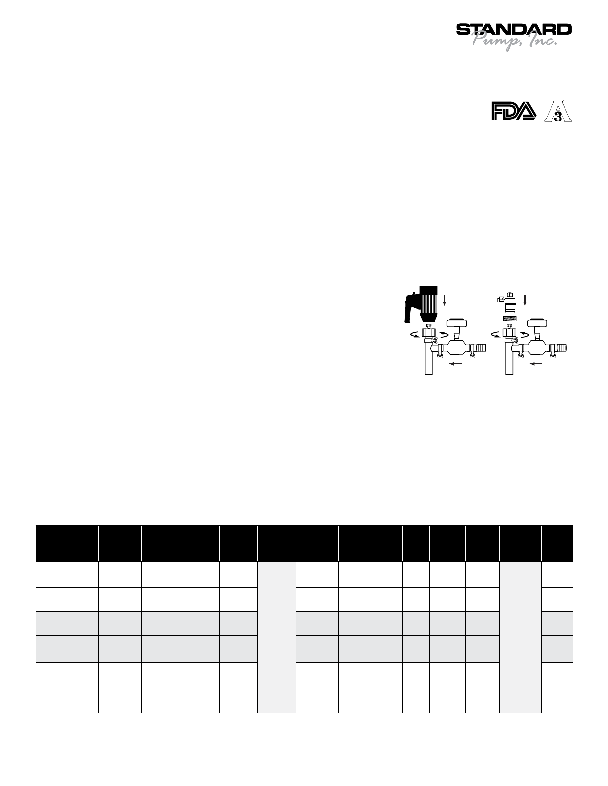
Assembly
1. Remove the pump, motor and from
packaging.
2. Inspect all contents for damage.
3. Couple the motor to the pump tube by
using the hex nut (see Figure 1).
4. Attach the meter to the pump discharge
using the supplied Tri-clamp®fitting (see
Figure 1).
5. It is recommended to thoroughly clean
and sanitize the Flow Meter System
before operation.
6. First pump clean water in order to
familiarize yourself with the pump’s
operation, flow rate, discharge pressure
and motor speed.
Figure 1
Electric Air


