ST&G L1321 AP User manual

Instructions for L1321 AP / AL
Polycentric 4 Bar
Mechanical Manual Locking Knee
ST&G USA Corp. Phone: (714) 524-0663
2691 Saturn St. Fax: (714) 364-8113
Brea, CA 92821 www.stngco.com

1. Description and purpose
Prosthetist instructions.
L1321 AP / AL knee is for lower limb prosthesis.
Recommended for K1, K2.
Weight limit for a user is up to 125kg / 275lbs
Ability to lock knee in full extension as part of rehabilitation process.
Can progress from locking to full-time unlocked knee.
Contra-indications
Residual muscular weakness, contractures or proprioceptive dysfunction
including poor balance.
Contra lateral joint instabilities or pathology
Complicated conditions involving multiple disabilities
Product Code
L1321 AP / AL
Polycentric 4-Bar Mechanical Manual Locking Knee
Ensure the end user has understood any Instructions for use, especially to
the safety information.
125kg
275lb

Fig. 1 (a) Posterior View, (b) Anterior View, c) Lateral View of Knee Unit
2 Construction
Principal Parts:
Frame Aluminum Alloy, Brass, Stainless Steel, Steel
Knee head Aluminum Alloy, Stainless Steel
Knee control Various materials principally Aluminum Alloy,
Stainless Steel, Poly Urethane, Copper
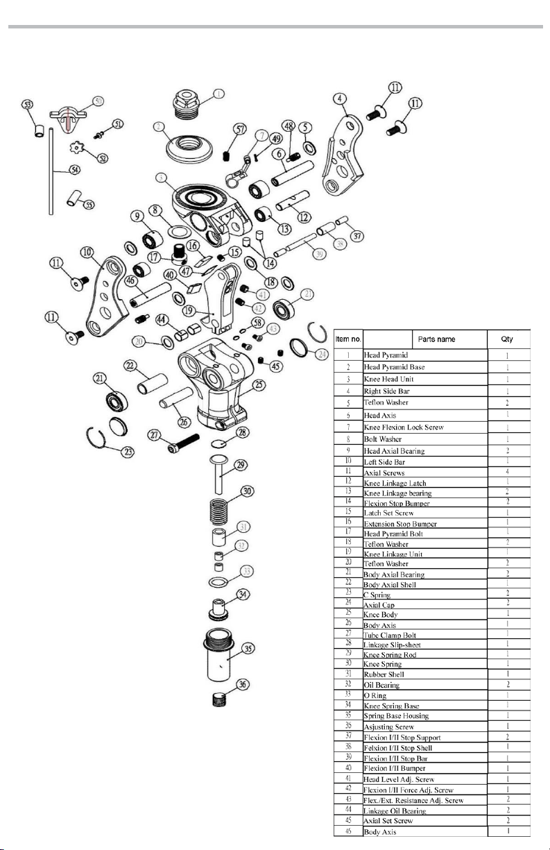
Exploded View

The Caution symbol highlights safety information which must be
followed carefully.
Be aware of finger trap hazard at all times
Any changes in performance of the knee e.g. instability or lag in transition
from full stance flexion moment to full knee extension moment in the
knee should be immediately reported to the Clinician / Practitioner
Any excessive changes in heel height may adversely affect the stability of
the knee.
The user should be advised to contact their Clinician / Practitioner if their
condition changes.
4. Safety Information
Always use a hand rail when descending stairs and at any other time if
available.
3 Function
Pyramid and Knee Disarticulation mounting options
30mm Tube Clamp distal mount
Adjustable spring extension assist
Adjustable friction
Manual lock can be disabled

5 Maintenance
Maintenance must be carried out by qualified personnel.
Bi-Annual inspection is recommended.
Check for visual defects that may affect proper function.
A loaner system is available should servicing be required.
The wearer should be advised:
Any changes in performance of this device must be
reported to the Clinician / Practitioner.
Changes in performance may include:
Increase in knee stiffness
Knee instability
Any unusual noises
Inability of lock to engage
Cleaning:
Use a damp cloth and mild soap to clean the outside surfaces.
DO NOT use aggressive cleaning agents.
If the limb/knee comes into contact with salt or chlorinated
water, it should be rinsed with fresh water and dried.
6 Limitations on use
Intended Life:
Service life of the product is covered by the warranty period (2 years)
This product is recommended for use with other ST&G Products.
Lifting Loads:
Amputee weight and activity is governed by the stated limits.
Combined amputee, and carrying load, should not be at, or exceed stated weight
limit.
Environment:
Avoid abrasive environments such as those containing sand for
example as these may promote premature wear. Avoid contact with
talcum powder.
Operating and Storage Temperature Range:
Exclusively for use between temperatures of -10˚C to 50˚C [14˚F and 122˚F]
7. Alignment and Set-Up
Users be aware of potential finger trap hazard
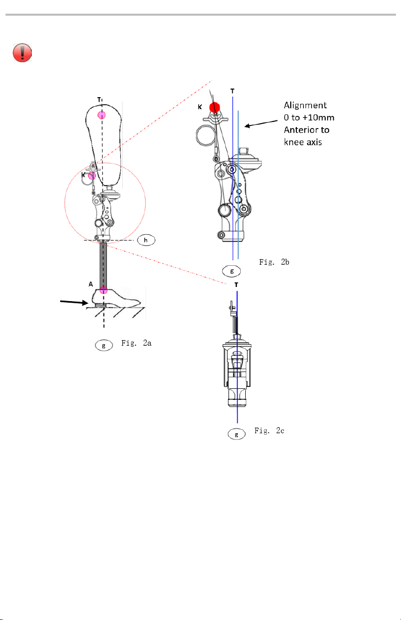
Note: 4-bar knees inherently are very stable due geometry built into each
design. This is commonly referred to as the Instant Knee Center (IKC). The
IKC point when doing bench alignment, will fall posterior and anterior to the
traditional TKA line that we will reference as Tg (Fig. 2a/b). Tg line in Fig. 2a is
ideal placement, but in certain instances, it may be necessary to
accommodate placement anteriorly (up to 10mm). The Tg line is referencing a
moving A/P weight bearing line, so it could be slightly anterior or neutral.
Add
3mm
safety
factor

a) With prosthesis assembled, taking into account hip flexion contractures,
abduction, Line Of Progression, and toe out (Fig.2a), the TKA plumb line
should pass through the knee center (center ot proximal/anterior pivot
Fig.2a, 2b) and in front of the IKC (red dot).
NOTE: Take into account shoe heel height, and add 3mm safety
factor.
b) Ideally, the pylon connecting the knee and foot should end up vertical.
There may be a variance due to the foot alignment recommendations. In
this case, the maximum anterior tilt of the pylon should not to exceed 3-4
degrees, and it may be necessary to utilize 1222T offset tube clamp
adapter. It is advised to follow up in 1-2 weeks to reassess the alignment.
c) With prosthesis donned, the weight line should pass through the
centerline of the knee in the Coronal or M/L plane (Fig. 2c). Excessive
outset or inset will put undue stress on the knee joint.
d) With prosthesis donned, the weight line for Sagittal or A/P plane should
have the plumb line passing ideally through the knee center (proximal
anterior pivot), and be perpendicular to the ground. (Fig. 2a, 2b)
7.1 BENCH ALIGNMENT:
It is not recommended to adjust the head tilt feature of
this knee, as it will possibly interfere with the lock
mechanism. Adjustment can lead to lock not engaging, or
to lock damage which will void the warranty!
Use 6mm hex wrench and turn:
Clockwise to increase extension assist.
Anti-clockwise to reduce extension assist.
After inserting pylon, apply thread
locker to the 5mm pinch bolt and torque
12Nm
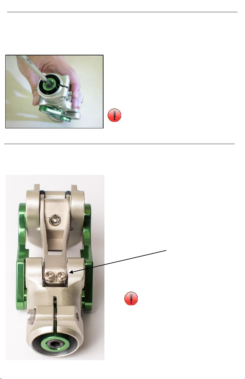
Use 3mm driver to turn both screws
on base of linkage:
Clockwise to increase friction.
Anti-clockwise to reduce friction.
Turn screws equally so friction
is distributed evenly on linkage
bearing.
8.2 Knee Friction Adjustment
8 Knee Adjustment
8.1 Knee Extension Assist Adjustment

With the lock lever in the
“Unlock” position, with 2.5mm
hex wrench, tighten set screw to
disable the lock function. Be
sure to tighten the screws on
both sides so that the lock lever
does not spring back to lock
position. The knee will then
function as a normal four bar
knee.
8.4 Lock Disable Mechanism
lock disable set screw
(Note: Total of 2 set
screws)
Lock Lever
Lock cable retainer screw can be removed to eliminate lock cable.
GAIT DEVIATIONS AND ADJUSTMENTS:
Excessive Heel Rise:
For excessive heel rise during walking, first try adjusting the knee friction
adjustment by turning it up to slow knee flexion initiation during swing. It might be
necessary to very slightly increase knee extension assist spring tension by 1/8 turn
increments. Increasing extension assist spring tension alone, will not reduce
excessive heel rise tendencies. (Refer to Section 8.3)
Terminal Impact:
Terminal Impact can be reduced by increasing knee friction through the two knee
friction adjustment screws. Be sure to adjust both screws symmetrically. Also, it
may be necessary to reduce the extension assist spring tension. (Refer to Section
8.3, 8.1)
For Unlocked gait Deviations

The following is not the preferred method, but should the situation arise, this
technique could be utilized as a temporary method!
Attachment of Lanyard Handle Star Nut:
The Star Nut needs to be laminated into the socket. Depending on the nut supplied,
the hole should be burnished through, and then:
If the Star Nut is not threaded, drill out with 3.3mm drill bit and tap with 4mm tap.
If the Star Nut is threaded, chase threaded nut to clean thread with 4mm tap.
If for some reason, the Star Nut is not laminated into the socket, a relief can be
sanded into the interior of the socket so that the Star Nut sits completely into the
relief and does not protrude into the socket –The location and amount the Star
Nut needs to be flush is to be determined by the Prosthetist.
Drill a corresponding hole the same size as the star nut hole into the determined
location that the Lanyard Handle will be.
After relief is achieved, the Star Nut can be Bonded into position with Acrylic
Sealing Resin with fiber filler, or Urethane Adhesive.
The Star Nut will need to be completely covered over, and the bonded area can
be covered with Masking Tape till the bond is totally cured.
Once cured, the hole should be burnished and chased with a tap, or drilled and
tapped –PLEASE REFER TO Attachment of Lanyard Handle Star Nut.
Once the location is set, drill a
corresponding hole the same size as
the Star Nut.
Sand down the inside of the socket
enough to have the Star Nut lay flush
with the socket surface.
You can locate the Star Nut with a
copper rivet that has petroleum jelly on
the tip and inserted through the hole
and the Star Nut placed onto it.
This will aid in locating the Star Nut
when bonding it in place –Be sure to
cover the nut entirely with enough to
have a flush inner surface!

Apply Masking tape over the whole area to enable a
smooth and relatively flat blended in surface –if the
rivet sticks through the tape, that is ok. You want to
be sure that the Star Nut is completely covered so it
stays in place when the hole is either chased, or
drilled and tapped.
After Star Nut bonding has cured:
If Star Nut is threaded, burnish a through hole, and
chase the threads with a 4mm metric tap.
If not threaded, burnish a through hole, re-drill a
clean hole, and tap with a 4mm metric tap.
Apply thread locker to the stud threads, and screw
the stud into the hole and into the Star Nut.
After determining the length needed for the cable,
run through the lanyard handle.
NOTE: Cable can be run through a housing.
NOTE: Lanyard handle may vary depending on
knee model used!
After the length is established, insert the handle so
the pull tabs are on the distal aspect when inserted
onto the stud.
NOTE: Do not tighten set screw completely in
case length needs to be adjusted!
Once length is established, the set screw(s) can be
tightened down.
NOTE: Be sure to leave some extra cable in
case some length adjustment may need to be
done at a later time!
NOTE: Be sure knee lock can cycle adequately
before delivering to your patient.

Use a small screw driver to pick
out the extension stop rubber
bumper on knee level adjusting
screw. Insert new one into slot.
9 Maintenance of Knee Unit
9.1 Servicing Extension Stop Bumper

10 Technical Specification
Operating & Storage Temperature Range: -10˚C to 50˚C ( 14˚F to 122˚F)
Weight (Pyramid / Lotus): 766 g (1lb 11oz)
Recommended Activity: K1, K2
Maximum User Weight: 125kg (275lbs)
Maximum flexion angle: 135 degrees
Proximal Alignment attachment: Rotatable Male Pyramid,
Lotus Adapter
Distal Alignment attachment: Tube Clamp
Tube clamp torque setting: 12Nm
Pyramid Center Bolt: 18Nm
Build Height (Pyramid / Lotus): 108mm / 114.3mm
Materials: Aluminum Alloy, Stainless Steel, Steel, Rubber
Build Height
Pyramid 108mm
Lotus 114.3mm

CE Conformity
This product meets the requirements of 93/42/EEC guidelines for medical products.
This product has been classified as a class I product according to the classification
criteria outlined in appendix IX of the guidelines. Please keep this manual in safe place
for future use.
10 Warranty
Warranted for 2 years from the date of invoice by ST&G.
The user should be aware that changes or modifications not approved will void the
warranty.
11 Liability
The manufacturer recommends using the device only under the specified conditions
and for the intended purposes. The device must be maintained according to the
instructions for use supplied with the device. The manufacturer is not liable for
damage caused by the component combinations that were not authorized by the
manufacturer.

ST&G USA Corporation
2691 Saturn Street, Brea, CA 92821, USA
Tel: 1-714-524-0663 Fax: 1-714-364-8113
L1321IFU Rev. B (01-19-18)
This manual suits for next models
1
Table of contents
Other ST&G Medical Equipment manuals


