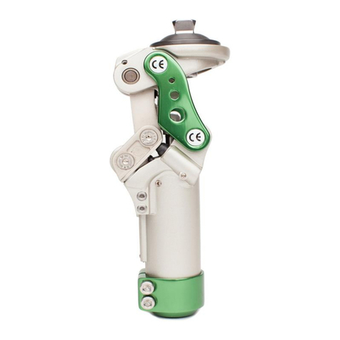
ST&G 1315S User manual

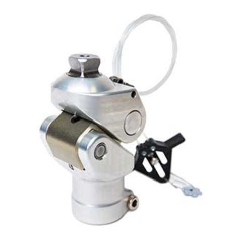
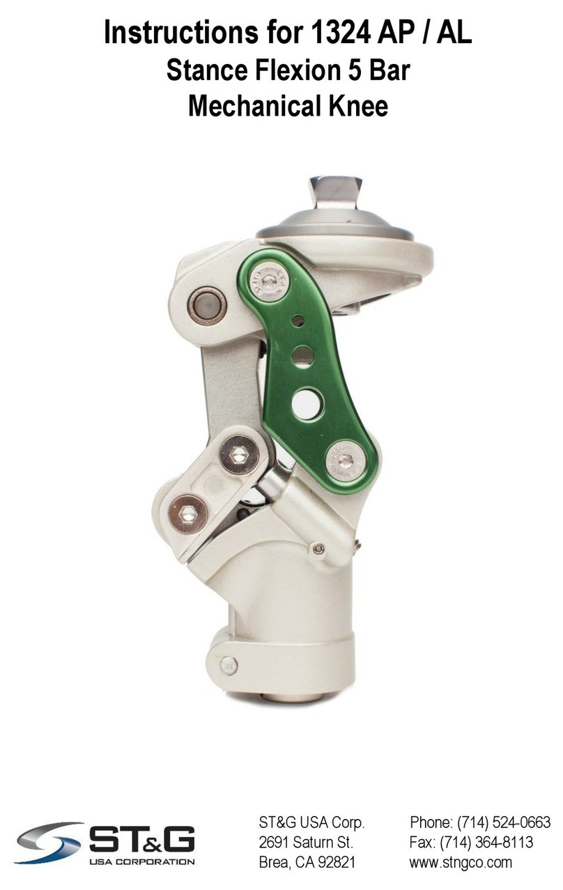
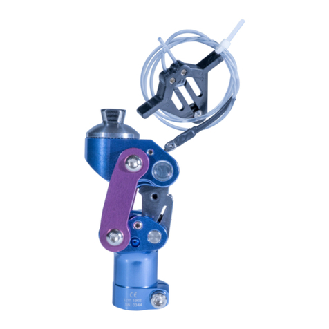
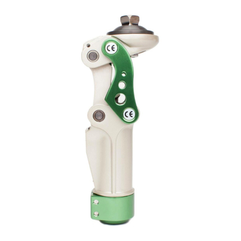
Instructions for 1315S/1315T
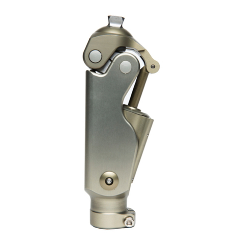
Mechanical 4 Bar Knee
with manual lock
ST&G USA Corp. Phone: (714) 524-0663
2691 Saturn St. Fax: (714) 364-8113
Brea, CA 92821 www.stngco.com

1 Description and purpose
Prosthetist instructions.
1315S/1315T knee is for lower limb prosthesis.
Recommended for K1.
Designed for low impact activity patient.
Weight limit for a user is up to 100kg/220lbs
Ability to get knee in full extension as part of rehabilitation process.
High need for safety.
Knee Disarticulation Level
Contra-indications
Residual muscular weakness, contractures or proprioceptive dysfunction
including poor balance.
Contra lateral joint instabilities or pathology
Complicated conditions involving multiple disabilities
Lack ability to adequately clear prosthetic side during swing
Product Code
1315S/1315T
Mechanical 4 Bar Knee with manual lock
100Kg/
220kg
Ensure the end user has understood any Instructions for use, especially to
the safety information.
2

2. Construction
Principal Parts 1315S
1315T
Frame Stainless Steel, Steel, Brass, Plastic
Titanium, Steel, Brass, Plastic

The Caution symbol highlights safety information which must be followed carefully.
Be aware of finger trap hazard at all times
Any changes in performance of the knee e.g. inability for lock to cycle, any
change in how the knee functions should be immediately reported to the
Clinician / Practitioner
Any excessive changes in heel height may adversely affect the ability to
lock the knee, and the stability of the prosthesis
The user should be advised to contact their Clinician / Practitioner if their
condition changes.
4 Safety Information
3 Function
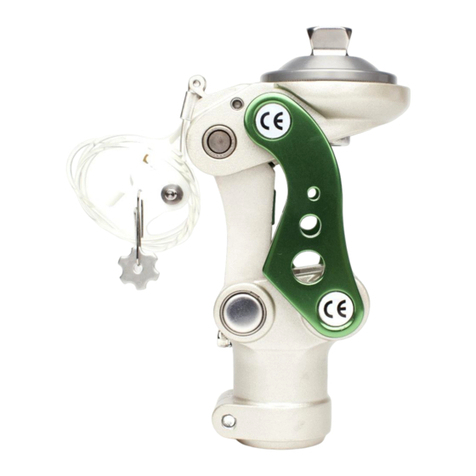
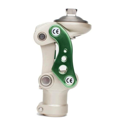
The 1315S / 1315T is a mechanical 4 Bar knee with manual lock
Knee Disarticulation proximal mounting option
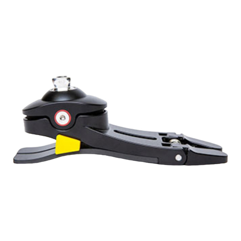
Pyramid distal mounting option
Knee is not be walked unlocked as a free knee joint. This will lead to
patient falling and is unsafe.

5 Maintenance
Maintenance must be carried out by qualified personnel.
Bi-Annual inspection is recommended.
Check for visual defects that may affect proper function.
A loaner system is available should servicing be required.
The wearer should be advised:
Any changes in performance of this device must be reported to the Clinician /
Practitioner.
Changes in performance may include:
Inability to cycle the lock of the knee
Any unusual noises
Cleaning:
Use a damp cloth and mild soap to clean the outside surfaces.
DO NOT use aggressive cleaning agents.
If the limb/knee comes into contact with salt or chlorinated water, it should be rinsed
with fresh water and dried.
6 Limitations on use
Intended Life:
Service life of the product is covered by the warranty period (1 year)
This product is recommended for use with other ST&G Products.
Lifting Loads:
Amputee weight and activity is governed by the stated limits.
Combined amputee, and carrying load, should not be at, or exceed stated weight limit.
Environment:
Avoid abrasive environments such as those containing sand for example as these may
promote premature wear. Avoid contact with talcum powder.
Operating and Storage Temperature Range:
Exclusively for use between temperatures of -10˚C to 50˚C [14˚F and 122˚F]

7 Alignment and Set-Up
Users be aware of potential finger trap hazard
Note: The 1315S/1315T is a mechanical 4 bar knee. 4 bar knees are inherently stable, but
care needs to be taken to properly bench align the knee with the prosthesis.
BENCH ALIGNMENT:
a) With prosthesis assembled, taking into account hip flexion contractures, abduction,
Line Of Progression, and toe out, the TKA plumb line should pass through the knee
center at the proximal/anterior pivot. Take into account shoe heel height, and add
3mm safety factor.
b) Foot placement versus the knee will be determined by the foot alignment
requirements. The knee should not tilt excessively more than 4 degrees anterior. It is
advised to follow up in 1-2 weeks to reassess the alignment.
c) The weight line should pass through the centerline of the knee in the Coronal or
M/L plane. Excessive outset or inset will put undue stress on the knee joint.
Set the bench alignment taking into account the heel height of associated footwear plus 3mm
safety factor!

8 Knee Adjustments
8.1 Friction Adjustment
NOTE: Friction adjustment for 1315S and 1315T .
Flexion Stop
NOTE: It is advisable to be sure that the mounting bracket portion of the
socket contacts the distal knee pivot aspect of the frame, and not the
posterior link! Damage could result from incorrect contact!
1315S / 1315T have friction adjustment located at both anterior pivot axis locations.
Friction
Adjustment
For friction adjustment:
Turn hex head cap screw using 5mm wrench while holding the nut on the opposite
side using the enclosed plastic tool. Turn the screw:
clockwise to increase friction
anti-clockwise to decrease friction.
NOTE: Adjustments of as little as 5 to 10 degrees provide a perceptible
change.
Plastic Tool
5mm wrench

Manual Lock Adjustment:
Manual lock has adjustabilitiy for sensitivity and to take up slack for wear.
IMPORTANT: Do not over tighten the adjustment screw, as the lock will take a
lot of effort to lock or may interfere with full engagement!
Manual Lock Adjustment
Screw. Use 4mm hex
wrench
Manual Lock adjustment:
Turn hex head cap screw using 4mm hex wrench.
Turn the screw:
Clockwise to increase friction
Anti-clockwise to decrease friction.
NOTE: Adjustments of as little as 5 degrees provide a perceptible change.

The following is not the preferred method, but should the situation arise, this
technique could be utilized as a temporary method!
Attachment of Lanyard Handle Star Nut:
The Star Nut needs to be laminated into the socket. Depending on the nut supplied,
the hole should be burnished through, and then:
If the Star Nut is not threaded, drill out with 3.3mm drill bit and tap with 4mm tap.
If the Star Nut is threaded, chase threaded nut to clean thread with 4mm tap.
If for some reason, the Star Nut is not laminated into the socket, a relief can be
sanded into the interior of the socket so that the Star Nut sits completely into the
relief and does not protrude into the socket –The location and amount the Star
Nut needs to be flush is to be determined by the Prosthetist.
Drill a corresponding hole the same size as the star nut hole into the determined
location that the Lanyard Handle will be.
After relief is achieved, the Star Nut can be Bonded into position with Acrylic
Sealing Resin with fiber filler, or Urethane Adhesive.
The Star Nut will need to be completely covered over, and the bonded area can
be covered with Masking Tape till the bond is totally cured.
Once cured, the hole should be burnished and chased with a tap, or drilled and
tapped –PLEASE REFER TO Attachment of Lanyard Handle Star Nut.
Once the location is set, drill a
corresponding hole the same size as
the Star Nut.
Sand down the inside of the socket
enough to have the Star Nut lay flush
with the socket surface.
You can locate the Star Nut with a
copper rivet that has petroleum jelly on
the tip and inserted through the hole
and the Star Nut placed onto it.
This will aid in locating the Star Nut
when bonding it in place –Be sure to
cover the nut entirely with enough to
have a flush inner surface!

Apply Masking tape over the whole area to enable a
smooth and relatively flat blended in surface –if the
rivet sticks through the tape, that is ok. You want to
be sure that the Star Nut is completely covered so it
stays in place when the hole is either chased, or
drilled and tapped.
After Star Nut bonding has cured:
If Star Nut is threaded, burnish a through hole, and
chase the threads with a 4mm metric tap.
If not threaded, burnish a through hole, re-drill a
clean hole, and tap with a 4mm metric tap.
Apply thread locker to the stud threads, and screw
the stud into the hole and into the Star Nut.
After determining the length needed for the cable,
run through the lanyard handle.
NOTE: Cable can be run through a housing.
NOTE: Lanyard handle may vary depending on
knee model used!
After the length is established, insert the handle so
the pull tabs are on the distal aspect when inserted
onto the stud.
NOTE: Do not tighten set screw completely in
case length needs to be adjusted!
Once length is established, the set screw(s) can be
tightened down.
NOTE: Be sure to leave some extra cable in
case some length adjustment may need to be
done at a later time!
NOTE: Be sure knee lock can cycle adequately
before delivering to your patient.

Key Dimensions:
9 Technical Specification (1315S/1315T)
Operating & Storage Temperature Range: -10˚C to 50˚C ( 14˚F to 122˚F)
Weight: 671g/916g
Recommended Activity: K2
Maximum User Weight: 125kg (275lbs)
Maximum flexion angle: 110 degrees
Proximal Alignment attachment: Low Profile Knee
Disarticulation Level
Distal Alignment attachment: Male Pyramid
Extension Assist: Adjustable Spring Extension Assist
Build Height: 118mm
Materials: Stainless Steel, Steel, Brass, Plastic / Titanium, Steel, Brass, Plastic

CE Conformity
This product meets the requirements of 93/42/EEC guidelines for medical products.
This product has been classified as a class I product according to the classification
criteria outlined in appendix IX of the guidelines. Please keep this manual in safe place
for future use.
10 Warranty
Warranted for 1 year from the date of invoice by ST&G.
The user should be aware that changes or modifications not approved will void the
warranty.
11 Liability
The manufacturer recommends using the device only under the specified conditions
and for the intended purposes. The device must be maintained according to the
instructions for use supplied with the device. The manufacturer is not liable for
damage caused by the component combinations that were not authorized by the
manufacturer.

ST&G USA Corporation
www.stngco.com e-mail: info@stngco.com
2691 Saturn Street, Brea, CA 92821, USA
Tel: 1-714-524-0663 Fax: 1-714-364-8113
1315IFU Rev. B (01-08-18)
This manual suits for next models
1
Table of contents
Other ST&G Medical Equipment manuals
Popular Medical Equipment manuals by other brands

Getinge
Getinge Arjohuntleigh Nimbus 3 Professional Instructions for use

Mettler Electronics
Mettler Electronics Sonicator 730 Maintenance manual

Pressalit Care
Pressalit Care R1100 Mounting instruction

Denas MS
Denas MS DENAS-T operating manual

bort medical
bort medical ActiveColor quick guide

AccuVein
AccuVein AV400 user manual
