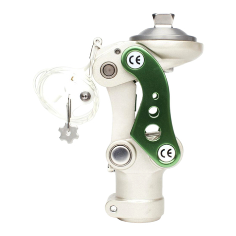
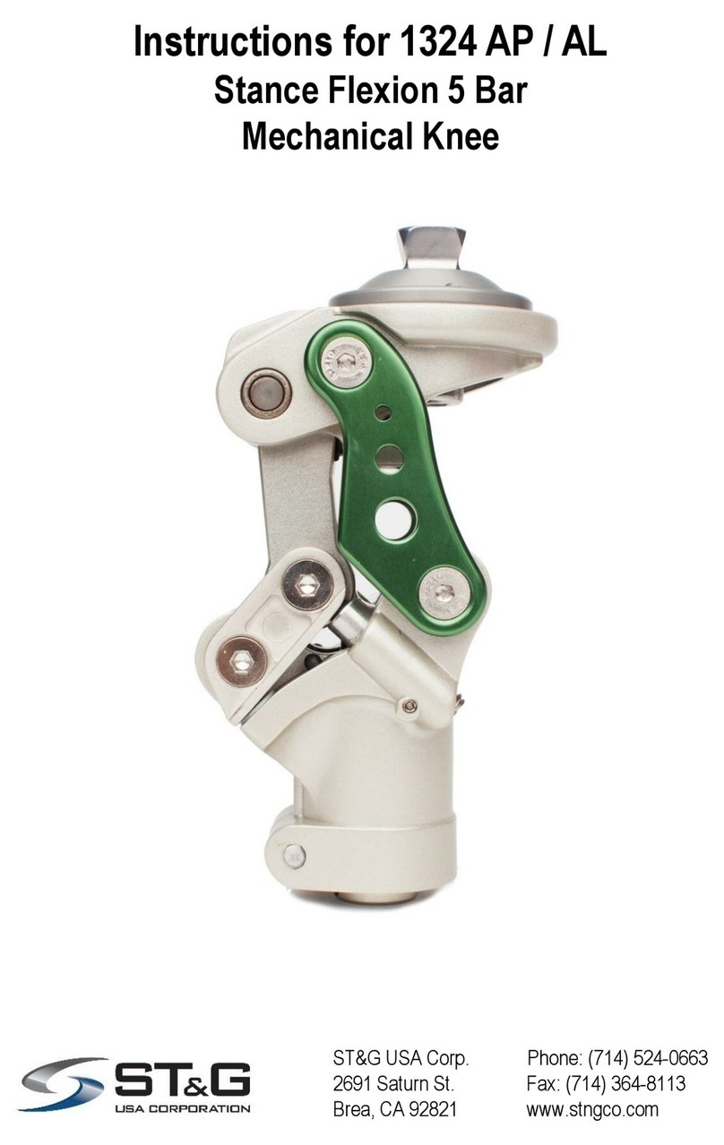
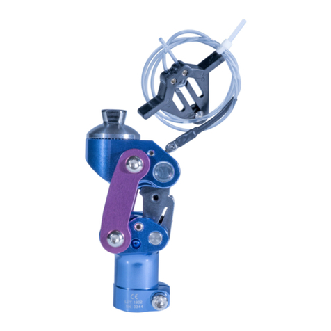
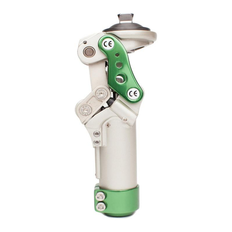
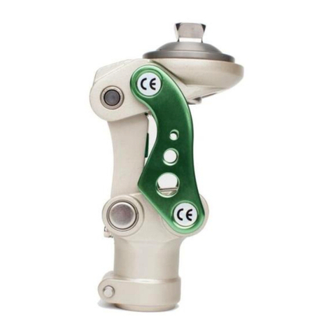
ST&G L1311A User manual

ST&G USA Corp. Phone: (714) 524-0663
2691 Saturn St. Fax: (714) 364-8113
Brea, CA 92821 www.stngco.com
Instructions for L1311A
Weight Activated Brake Knee
with Manual Lock

1 Description and purpose
Prosthetist instructions.
L1311A knee is for lower limb prosthesis.
Recommended for K1 up to K2.
Weight limit for a user is up to 125kg / 275lbs
Ability to lock knee in full extension as part of rehabilitation process.
Can progress from locking to full-time unlocked weight activated brake knee.
Contra-indications
Residual muscular weakness, contractures or proprioceptive dysfunction
including poor balance.
Inability to comprehend instructions
Contra lateral joint instabilities or pathology
Complicated conditions involving multiple disabilities
Product Code
L1311A
Mechanical Single Axis Knee Joint with Brake Function and Optional Manual Lock
125Kg
275lbs
Ensure the end user has understood any Instructions for use, especially to
the safety information.

2. Construction
Principal Parts
Frame Aluminum Alloy
Knee control Various materials principally Aluminum Alloy, Brass, Stainless
Steel, Poly Urethane

The Caution symbol highlights safety information which must be followed carefully.
Be aware of finger trap hazard at all times
Any changes in performance of the knee e.g. inability to engage manual
lock mechanism, instability or lag in transition from flexion moment to full
knee extension moment in the knee, or unusual noise should be
immediately reported to the Clinician / Practitioner
Any excessive changes in heel height may adversely affect the stability of
the knee.
The user should be advised to contact their Clinician / Practitioner if their
condition changes.
4 Safety Information
3 Function
Pyramid proximal mount
30mm distal tube clamp mount
Adjustable integrated spring extension assist
Adjustable weight activated brake sensitivity
Adjustable swing friction
Dual function manual lock lanyard handle
Manual lock can be disabled
Enables easy switching between locked knee and free weight activated brake knee
Overview
Due to unique construction, the L1311A knee joint can be used both as a locking
joint with manual release, and as a weight activated brake knee joint as the
user's mobility progresses. The L1311A is particularly suitable for above-knee
amputees with a high need for safety as the innovative brake mechanism
increases the safety of the knee which can help compensate for some reduced
muscle activity of the hip.

5 Maintenance
Maintenance must be carried out by qualified personnel.
Bi-Annual inspection is recommended.
Check for visual defects that may affect proper function.
A loaner system is available should servicing be required.
The wearer should be advised:
Any changes in performance of this device must be
reported to the Clinician / Practitioner.
Changes in performance may include:
Increase in knee stiffness
Inability to easily lock the knee with full extension
Knee instability
Any unusual noises
Cleaning:
Use a damp cloth and mild soap to clean the outside surfaces.
DO NOT use aggressive cleaning agents or lubricants.
If the limb/knee comes into contact with salt or chlorinated water,
or bodily fluids, it should be rinsed with fresh water and dried
6 Limitations on use
Intended Life:
Service life of the product is covered by the warranty period (2 years)
This product is recommended for use with other ST&G Products.
Lifting Loads:
Amputee weight and activity is governed by the stated limits.
Combined amputee, and carrying load, should not be at, or exceed stated weight limit.
Environment:
Avoid abrasive environments such as those containing dust or sand for
example as these may promote premature wear. Avoid contact with
talcum powder.
Operating and Storage Temperature Range:
Exclusively for use between temperatures of -10˚C to 50˚C [14˚F and 122˚F]

7 Alignment and Set-Up
Users be aware of potential finger trap hazard
Alignment for the L1311A should be adhered to so as to enable a stable and safe functioning
prosthesis for the wearer. The recommended alignment is 10mm anterior to the Knee Center
which will have the weight line on the centerline along the length of the pylon. Weight line
should also be along the centerline of the pylon in the sagittal plane so as to not promote
undue stress on the knee joint axis.
Important: If the weight line is too close to the knee center, there is possibility of inadvertent
knee instability. Adhere to allowance for safety factor of at least 3mm for initial fitting, and to
reassess knee alignment and function on a regular basis initially (especially for new
amputees) so as to gauge their progression and ability with the need for fine tuning knee
function!
Set the bench alignment taking into account the heel height of associated footwear plus
3mm safety factor!
It is not recommended to have alignment too close to the knee center, as it could
cause knee instability or inconsistent weight activation of brake!
Bench Alignment:
Weight line 10mm
Anterior to knee center
(centerline of pylon)
Do not insert any tube spacers into tube clamp section –This can lead to
potential failure. Only the intended pylon should be fully inserted to the tube
clamp bottom.

The L1311A is supplied by the factory in the basic setting.
Carefully assess the brake function with the wearer during the dynamic initial
fitting to see if the basic setting is optimal.
If adjustment is necessary, it is best to start with the Stance Phase adjustment and
then go to Swing Phase adjustments.
NOTE: There is a fine balance to adjusting this so as to ensure that the wearer will
have a smooth transition to swing. Overly adjusting will cause the knee to not
release during swing initiation!
8 Knee Adjustment
8.1 STANCE PHASE - Brake Sensitivity Stance Adjustment
The brake sensitivity adjustment is to fine tune the
amount of load required during stance phase to activate
the brake mechanism.
Brake sensitivity adjustment screw location on L1311A
To access the adjustment screw, be sure the knee is
unlocked and flex to fully expose the adjustment screw on
the brake mechanism face (fig. 1)
Using a 4 mm hex wrench turn adjustment screw:
Clockwise requires more weight needed to initiate the
brake function so the brake effect is induced later
(fig. 1)
Anti-Clockwise requires less weight needed to initiate
the brake function so the brake effect is induced earlier
(fig. 1)
NOTE: Adjustment as little as 5 degree turn makes a
notable difference!
Resetting Brake sensitivity to factory setting: Brake
sensitivity adjustment screw head should be flush with
the knee brake mechanism surface.
Fig. 1
Note that knee is flexed
to expose screw
Less More
weight needed

The Knee Friction Adjustment screw is located
towards the bottom of the knee joint on the
anterior and can be adjusted with a 3mm hex
wrench. (fig. 2)
Readjusting the knee friction setting.
NOTE: Minor adjustments of as little as 3 degree
turn will provide a notable difference!
The knee friction effect may occur anyway during
initial swing (prosthesis sticks) depending on the
user’s weight or walking habits which could
impair the safety and the user’s walking behavior.
In this case, the knee friction screw can be turned
using a 3mm hex wrench:
Anti-Clockwise to reduce friction/sticking during
initial swing. Reassess knee function during
walking and adjust accordingly.
Important: flexion and extension must be possible
at all settings!
8.2 SWING PHASE - Friction Adjustment
Less More
Friction
Fig. 2
Note that the screw is on the
bottom.
Clockwise = increased friction
Anti-Clockwise = reduced friction
(Screw accessed above it is knee
axis pin retainer screw)
The Knee Spring Extension Adjustment screw is
located within the tube clamp portion of the knee
joint, and is adjusted with a flat blade screw
driver. (fig. 3)
Using a flat blade screw driver, the spring
extension assist adjustment screw can be turned:
Clockwise for increased extension assist.
Anti-Clockwise for reduced extension assist.
Important: Knee action should be smooth. This
knee is a low activity knee, so do not expect for
very rapid extension assist to occur. Excessive
spring tension could possibly affect knee friction
tension.
Be sure that the 5mm Hex Wrench Tube Clamp
Pinch Bolt torque is set to 16Nm.
8.3 SWING PHASE –Spring Extension Assist
Less More
Extension Assist
Fig. 3
Note that the screw is
inside the tube clamp.
(Screw accessed by
removing pylon from
knee unit tube clamp)
Resetting Friction to factory setting: Friction adjustment screw should be
reset to be flush with knee frame surface.

8 Knee Adjustment
8.4 Unlocked Knee Mode - Manual Lock Disable Procedure
Manual Lock Disable:
Lock mechanism-
• Push the locking lever (a) upwards and hold
it in this position (fig. 7)
• Lanyard can be removed by removing the
retainer screw with 2.5mm hex wrench.
• Secure locking lever (a) in this position by
turning the set screw (b) with a 2.5 mm hex
wrench clockwise. Apply thread locker!
a
b
Note: Lock should only be disabled by the prosthetist when patient
has been released to have the ability to control the prosthesis
without the need for the manual lock mechanism!
IMPORTANT: Set screw (b) should be tightened to a torque of 5 Nm
and secured with thread locker when finishing the prosthesis. Do not
over tighten! Use a torque wrench!
Note: Failure to adequately secure the set screw (b) when disabling
the locking lever (a), can result in loss of function of the knee and /
or makes it impossible to move the knee freely.
Note: If being used with the locking function, the disable set screw
(b) must not impede the function of the locking lever (a) and must
be secured with Loctite to rule out inadvertent loosening and
inadvertent function.

Setting the Dual Function Lanyard Handle on the Lanyard Cable:
Once the retainer screw is mounted with the star nut on the socket (refer to
“Attachment of Lanyard Handle Star Nut:” section).
Setting the Lanyard Cable length:
• Unlock knee and flex the prosthesis.
• set the length by pulling the slack out of the cable from the lock lever and
lanyard handle with the lanyard handle set in the “knee lock range” side of the
retainer tabs making sure that the lock is pushed down so it is not completely at
the maximum open range.
NOTE: We want to be sure that the lock will release by simply pulling up on the
lanyard handle till the retainer tabs are encountered, and that the knee will again
lock by releasing the lanyard handle.
• Set the lanyard handle cable retainer screw so it is snug, but not crushing the
cable as to make further adjustment easier.
• Confirm lock mechanism function by cycling the lanyard handle to assess that
the knee lock lever does lock in a completely extended position, and unlocks to
allow knee flexion in the “knee lock range” of the handle.
• Confirm lock mechanism stays temporarily unlocked by having prosthesis fully
extended/locked, and pull on the lanyard handle past the retainer tabs.
Prosthesis should be able to flex without holding lanyard handle.
• Readjust cable as needed.
• If used with the locking function, the locking lever or lanyard cable must not be
impeded by the cosmesis. The cable must run freely.
IMPORTANT! Secure the cable so that it cannot catch in grinding tools when
modifications are required to socket! Hazard potential!
The Dual Function Lanyard Handle
The Dual Function Lanyard Handle has the ability to keep the knee in either the
temporary unlocked or locked position.
Knee lock range
Knee unlock range
Retainer tabs
Cable retainer set
screw locations
Lanyard cable entry and
exit holes

The following is not the preferred method, but should the situation arise, this
technique could be utilized as a temporary method!
Attachment of Lanyard Handle Star Nut:
The Star Nut needs to be laminated into the socket. Depending on the nut supplied,
the hole should be burnished through, and then:
If the Star Nut is not threaded, drill out with 3mm drill bit and tap with 4mm tap.
If the Star Nut is threaded, chase threaded nut to clean thread with 4mm tap.
If for some reason, the Star Nut is not laminated into the socket, a relief can be
sanded into the interior of the socket so that the Star Nut sits completely into the
relief and does not protrude into the socket –The location and amount the Star
Nut needs to be flush is to be determined by the Prosthetist.
Drill a corresponding hole the same size as the star nut hole into the determined
location that the Lanyard Handle will be.
After relief is achieved, the Star Nut can be Bonded into position with Acrylic
Sealing Resin with fiber filler, or ST&G Glu-It Urethane Adhesive.
The Star Nut will need to be completely covered over, and the bonded area can
be covered with Masking Tape till the bond is totally cured.
Once cured, the hole should be burnished and chased with a tap, or drilled and
tapped –PLEASE REFER TO Attachment of Lanyard Handle Star Nut.
• Once the location is set, drill a corresponding
hole the same size as the Star Nut (3mm bit).
• Sand down the inside of the socket enough
to have the Star Nut lay flush with the socket
surface.
• You can locate the Star Nut with the
associated screw (if threaded, otherwise utilize
a rivet) that has petroleum jelly on the threads
and inserted through the hole and the Star Nut
very slightly screwed onto it (fig a).
• Use Urethane Adhesive, such as ST&G Glu-
It, or bonding resin with filler, and be sure to
cover the nut entirely with enough to have a
flush inner surface! (fig. b)
•Slightly tighten the screw to draw in the Star
Nut to the socket wall
Fig. a
Fig. b

Apply Masking tape over the whole area to enable a
smooth and relatively flat blended in surface –if the
screw sticks through the tape, that is ok. You want
to be sure that the Star Nut is completely covered
so it stays in place when the hole is either chased,
or drilled and tapped.
After Star Nut bonding has cured:
If Star Nut is threaded, burnish a through hole, and
chase the threads with a 4mm metric tap.
If not threaded, burnish a through hole, re-drill a
clean hole, and tap with a 4mm metric tap.
Apply thread locker to the stud threads, and screw
the stud into the hole and into the Star Nut.
After determining the length needed for the cable,
run through the lanyard handle.
NOTE: Cable can be run through a housing.
NOTE: Lanyard handle is a dual function type
that can hold knee unlocked when pulled past
the retainer screw.
After the length is established, insert the handle so
the pull tabs are on the distal aspect when inserted
onto the stud.
NOTE: Do not tighten set screw completely in
case length needs to be adjusted!
Once length is established, the set screw(s) can be
tightened down.
NOTE: Be sure to leave some extra cable in
case some length adjustment may need to be
done at a later time!
NOTE: Be sure knee lock can cycle adequately
before delivering to your patient.

Key Dimensions:
9 Technical Specification
Operating & Storage Temperature Range: -10˚C to 50˚C ( 14˚F to 122˚F)
Weight: 495g
Recommended Activity: K1, K2
Maximum User Weight: 125kg (275lbs)
Maximum flexion angle (without socket): 145 degrees
Proximal Alignment attachment: Pyramid
Distal Alignment attachment: 30mm Tube Clamp
Tube clamp torque setting: 16Nm
Build Height: 65mm
Swing Phase: Integrated Extension Spring
Stance Phase: Optional lock or weight activated
Brake Mechanism
Materials: Aluminum Alloy, Stainless Steel, Steel, Urethane
Build Height:
Component = 65mm
Knee Center to mid ball = 26mm

CE Conformity
This product meets the requirements of 93/42/EEC guidelines for medical products.
This product has been classified as a class I product according to the classification
criteria outlined in appendix IX of the guidelines. Please keep this manual in safe place
for future use.
10 Warranty
Warranted for 2 years from the date of invoice by ST&G.
The user should be aware that changes or modifications not approved will void the
warranty.
11 Liability
The manufacturer recommends using the device only under the specified conditions
and for the intended purposes. The device must be maintained according to the
instructions for use supplied with the device. The manufacturer is not liable for
damage caused by the component combinations that were not authorized by the
manufacturer.

ST&G USA Corporation
2691 Saturn Street, Brea, CA 92821, USA
Tel: 1-714-524-0663 Fax: 1-714-364-8113
L1324IFU Rev. A (05-09-18)
Table of contents
Other ST&G Medical Equipment manuals
