StarLeaf Teamline 5140 User manual

Teamline 5140
Installation Guide
22 May 2019

Teamline 5140 Installation Guide Page 1
Contents
Teamline 5140 1
Installation Guide 1
22 May 2019 1
Before you install Teamline 5140 4
Prerequisites 4
Skype for Business and Exchange requirements 4
About the Teamline 5140 system 6
The connectors 6
Dimensions 6
Connecting Teamline 5140 to peripherals 8
Positioning the Teamline 5140 system 8
Connecting network cables 8
Connecting the StarLeaf Touch 8
Connecting the touchscreen to the Teamline system 9
Connecting the camera and microphone 9
Connecting displays and audio 10
Extending cables 10
Connecting Pronto 10
Mounting Pronto 11
Connecting power 12
Mounting the Teamline 5140 system 13
Mount dimensions 15
Configuring Teamline 5140 16
Connecting the system to Maestro 16
Configuring the proxy server (optional) 17
Changing system settings 17

Teamline 5140 Installation Guide Page 2
Using a static IPaddress 17
Ports and protocols 18
Room system connectivity 18
Outbound 18
Inbound 18
On-premise Skype for Business 2015 or Lync 2013 18
Outbound 19
Teamline systems on external networks 19
Skype for Business Online 20
Outbound 20
Inbound 21
Internal for Teamline 5140 21
System LED behavior 23
Network port LED 23
Using cameras with Teamline 5140 24
Setting up the Logitech MeetUp camera 25
Installing cameras 25
Examples of the maximum field of view 25
Logitech BRIO and Rally 1.5m 25
VHD-V71 at 2m 26
Logitech MeetUp at 2m 26
Installing the VHD-V71 camera 27
Microphone selection, placement, and setup 28
Pinout for StarLeaf microphone cable 30
The connectors and pin positions 30
Cable recommendations for room systems 31
HDMI cables 31

Teamline 5140 Installation Guide Page 3
USB cables 31
Camera cables 31
VISCA cable requirements 32
Pinout 32
Cable color information 33
Teamline 5140 safety and compliance information 34
Installation 34
Ventilation 34
Servicing 34
Power requirements 34
Operating environment 34
Approvals information 35
EU/EEC 35
Legal information 36
Third party software acknowledgments 36
Disclaimers and notices 36

Teamline 5140 Installation Guide Page 4
Before you install Teamline 5140
Before you install Teamline 5140
Before installing the Teamline system, read the Teamline 5140 safety and
compliance information.
Prerequisites
Ensure you have:
nOne or two commercial displays that support a 1080p60 input format
Note: Interlaced input is not supported.
nDisplays with an audio-output capability and a spare HDMIinput. If the
displays have Game Mode or PC Mode, enable one of these options to
reduce media processing delays and improve video experience
nA camera
nMicrophone(s)
Skype for Business and Exchange requirements
The Teamline system supports:
nLync 2010 Server
nLync 2013 Server
Note: If the deployment is not a Lync 2013 server, ensure that the Lync 2013
user interface is enabled.
nSkype for Business 2015 Server
nSkype for Business Online
nExchange 2010 SP2 Server
nExchange 2013 Server
nExchange Online
Teamline systems require a room resource mailbox in Exchange and a Skype
for Business user account that is associated with the room. For more details
about provisioning room system accounts, refer to Provisioning Skype Room
System accounts in Office 365 on the Microsoft website.
To set up the room for Skype for Business:
1. Identify the resource room mailbox in Exchange or create a new resource
mailbox.
2. Connect to Exchange Online PowerShell to set or create the mailbox
account. For instructions on connecting to Exchange Online PowerShell,
refer to the Microsoft website at: Connect to Exchange Online PowerShell
3. Assign a Skype for Business Online license. You can then log in using Skype
for Business to validate that the account is active.

Teamline 5140 Installation Guide Page 5
Before you install Teamline 5140
4. Check the Get-CalendarProcessing calendar processing options for the
room mailbox as follows:
nMeeting invitation emails sent to Teamline systems must contain the
attachments created by the calendar event. Otherwise, the Join Now tile
will not be displayed and meetings cannot be joined using the touchscreen.
Automatic email responses may delete attachments; ensure automatic
responses are configured to keep attachments.
nThe Teamline room display shows the titles of upcoming meetings. By
default, the organizer's name in the Exchange calendar is displayed as the
meeting title. To display the meeting title in the room, set
AddOrganizerToSubject and DeleteSubject to False. For more information,
see this Microsoft article.
For on-premise deployments, if the Skype for Business server certificates were
issued by a private certificate authority, ensure you have the certificate of the
Root Certificate Authority and any intermediate certificates. For more
information, see How to export Root Certification Authority Certificates on the
Microsoft website.

Teamline 5140 Installation Guide Page 6
About the Teamline 5140 system
About the Teamline 5140 system
The connectors
The following figure shows the connectors on the rear of the Teamline system:
Connector Description
1Power A DC +19V power connector. The system automatically adjusts to the
supply voltage. Use the supplied power cable to connect the system
to the power. Connect all other cables before connecting the power
2Display 1 Mini display connectors. These connectors output video (1080p60 only)
to the display
3Network 10/100/1000 Mbit/s auto-sensing Ethernet port. Connect to the network
4Microphone USB connector. Connect a StarLeaf microphone
5Display 2 Mini display connectors. These connectors output video (1080p60 only)
to a second display (if present)
6USB 2.0 USB connectors for Pronto or cameras
7Camera
(USB 3.0)
USB 3.0 connector for cameras
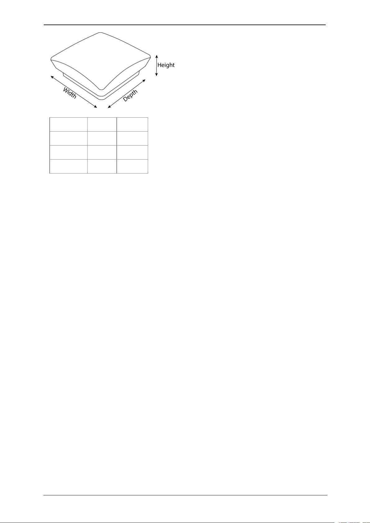
Dimensions
The Teamline 5140 system is designed so that it doesn't need to be rack
mounted; however, it can be wall mounted or mounted to the back of your
display.
Note: If you are using wireless (for example, Miracast) to connect devices to
present content in meetings, ensure the system is not enclosed in a rack or
behind a display. Otherwise, the wireless signal may not function.
Teamline 5140 Installation Guide Page 7
About the Teamline 5140 system
Dimension Metric Imperial
Width 150 mm 5.9 in
Depth 152 mm 5.98 in
Height 57 mm 2.24 in

Teamline 5140 Installation Guide Page 8
Connecting Teamline 5140 to peripherals
Connecting Teamline 5140 to peripherals
What's in the box?
nTeamline 5140 room system
nStarLeaf Touch touchscreen controller
nPronto
nWall mounting kit
nCables
lPower cable
lEthernet cable
lTwo HDMI to HDMI cables (1.8 meters/5.9 feet)
lPatch cable (2 meters/6.6 feet)
lUSBA to mini B (2.5 meters/8.2 feet)
nTwo Mini DisplayPort to HDMI adaptors
nStarLeaf microphone
nA camera and where applicable, camera cables, mounting kit, and
camera power supply
Positioning the Teamline 5140 system
1. Choose an appropriate installation site:
lThe system must be accessible to ensure all cables are easily connected
lProvide ventilation for the system; leave a space of at least 10cm (4
inches) behind, in front, and to the left and right of the system
lUse a grounded AC power outlet for the system
2. Wall mount the system or place on a firm horizontal surface. For information,
refer to Mounting the Teamline 5140 system.
Connecting network cables
Using an Ethernet cable, connect the Network port on the rear of the system
to an Ethernet switch in your network. The Ethernet port is a 10/100/1000
Mbit/s auto-sensing port and is set to ‘auto’ by default.
Note: If your network doesn't support automatic detection, you can
configure the network speed manually. On the touchscreen controller that
you have connected to the system, go to settings > networking > network
port speed and select 100Mb/s (full).
Connecting the StarLeaf Touch
Using an Ethernet cable, connect the PoE Network port on the rear of the
touchscreen to an Ethernet switch in your network. The Ethernet port is a
10/100/1000 Mbit/s auto-sensing port and is set to ‘auto’ by default. The
touchscreen needs a switch/port that supplies PoE to function.

Teamline 5140 Installation Guide Page 9
Connecting Teamline 5140 to peripherals
Note: The speed and duplex settings at either end of the connection must be
identical. Using non-matching settings causes severe packet loss.
Connecting the touchscreen to the Teamline system
Before you can use the StarLeaf Touch for your meetings, you must pair it with
the Teamline system. To do this:
1. Connect the touchscreen to a Power over Ethernet (PoE) enabled port.
2. On the touchscreen, double-tap to display the settings page.
3. Tap the networking tab and use the toggle to turn off auto-discovery. The
configuration server field is displayed.
4. In the configuration server field, enter the MAC address printed on the
bottom of the Teamline system.
The touchscreen will attempt to establish a connection to the Teamline system
using IPv6 before the system will establish a connection to the LAN (IPv4). Both
the touchscreen and the Teamline system must be on the same VLAN. In most
cases, the VLAN and subnet are the same. If the touchscreen cannot
establish an IPv6 connection to the codec, a failure message is displayed.
The IPv6 addresses are derived using the MAC address of each device. These
addresses are used to establish a local connection between the touchscreen
and the Teamline system. This is called an IPv6 link local address.
You can pair the touchscreen and Teamline system across different physical
switches as long as they are both on the same VLAN.
Once the touchscreen and Teamline system have successfully paired, the
touchscreen sends the network settings (DHCP or static) to the Teamline
system. The Teamline system establishes an IPv4 address and connection to
the corporate LAN. If the Teamline system cannot establish a connection to
the corporate LAN, a failure message is displayed. In this case, the
touchscreen and Teamline system are still paired.
Connecting the camera and microphone
To connect the camera and microphone:
1. Connect the camera to the Teamline system with the USB cable:
lIf you have a PTZ USB camera, connect it to the Camera USB connector.
This is a blue USB 3.0 connector
lIf you are using a static USB camera (such as the Logitech BRIO),
connect it to one of the pair of USB 2.0 connectors at the bottom of the
rear panel
2. Connect one or two StarLeaf microphones to the Microphone USB
connector.

Teamline 5140 Installation Guide Page 10
Connecting Teamline 5140 to peripherals
For more information about microphones, see Microphone selection,
placement, and setup.
If you have a dual display system, it is recommended that the camera is
mounted on the display that contains the view of the main video
(telepresence screen 1). For more information about cameras, see Using
cameras with Teamline 5140.
Note: If you are using the Logitech Meetup camera, ensure you are running
the latest version of the camera firmware. Otherwise, camera PTZ controls
may not work properly on the touchscreen. For more information and to
download firmware, go to the downloads area on the Logitech support site
here: https://support.logitech.com/en_gb/product/meetup-
conferencecam/downloads.
Connecting displays and audio
The audio emits from the Mini DisplayPort connectors on the rear of the
system. Connect directly from the Mini DisplayPort to the screen using the
supplied cable and adaptor. To do this, connect a Mini DisplayPort connector
on the Teamline 5140 to a screen using a a Mini DisplayPort-to-HDMI adaptor
and an HDMI-to-HDMI cable. For a two display system, connect the second
display in the same way.
Prior to GTm version 1.2, the supplied audio injector is required to connect the
displays to the Teamline 5140. In later versions, you can connect directly from
the Mini DisplayPort to the display using the supplied cables, without the need
for an audio injector.
Note: If you have a Teamline 5140 system installed with an audio injector and
you want to re-install it without the audio injector, contact StarLeaf Technical
Support.
Extending cables
For information about supported cable extenders and cable information, see
Cable recommendations for room systems.
Connecting Pronto
Pronto can be connected to devices (such as laptops) to share content and
audio, and display current meetings on the Touch and room display, even if
the room is not invited to the meeting. When connected to the device, Pronto
detects active meetings in the user's Outlook calendar, then enables the Join
now tile on the Touch to allow users in the room to join the meeting.

Teamline 5140 Installation Guide Page 11
Connecting Teamline 5140 to peripherals
Connect Pronto to the USB connector on the Teamline system using the USB-A
cable, and ensure the other end of the cable is accessible to users to plug into
their laptops. The first time users plug Pronto in, instructions are shown on the
room display:
When the Pronto app is launched, the presentation source screen is shared to
the room on the display and active meetings are displayed as a Join now tile
on the Touch and on the room display. Future meetings in the user's Outlook
calendar that start within the next 15 minutes are displayed on the Touch and
are visible on the room display. On subsequent connections using Pronto, the
app does not need to be launched and content and meetings are shared
immediately with the room.
Mounting Pronto
The supplied bracket can be used to mount Pronto to a surface using screws,
ties (such as cable ties or Velcro), or adhesive mounting pads. Remove Pronto
from the bracket to access the screw holes and slots for ties:

Teamline 5140 Installation Guide Page 12
Connecting Teamline 5140 to peripherals
Connecting power
Using the supplied power cable, connect the DC +19V power connector on
the rear of the system to the mains power.

Teamline 5140 Installation Guide Page 13
Mounting the Teamline 5140 system
Mounting the Teamline 5140 system
The Teamline 5140 system is shipped with a mounting kit containing a VESA
mount bracket, which can be used to mount the system to the back of a
display or to a wall.
Note: If you are using a wireless connection to share content in meetings
(such as Miracast), do not mount the system behind the display. This may
interfere with or prevent the wireless signal.
To attach and use the VESA bracket with a display:
1. Use the four small black screws that are included with the mount to attach
the VESA bracket to the back of the display.
2. Attach the two slightly larger black screws to the bottom chassis cover of the
Teamline system.
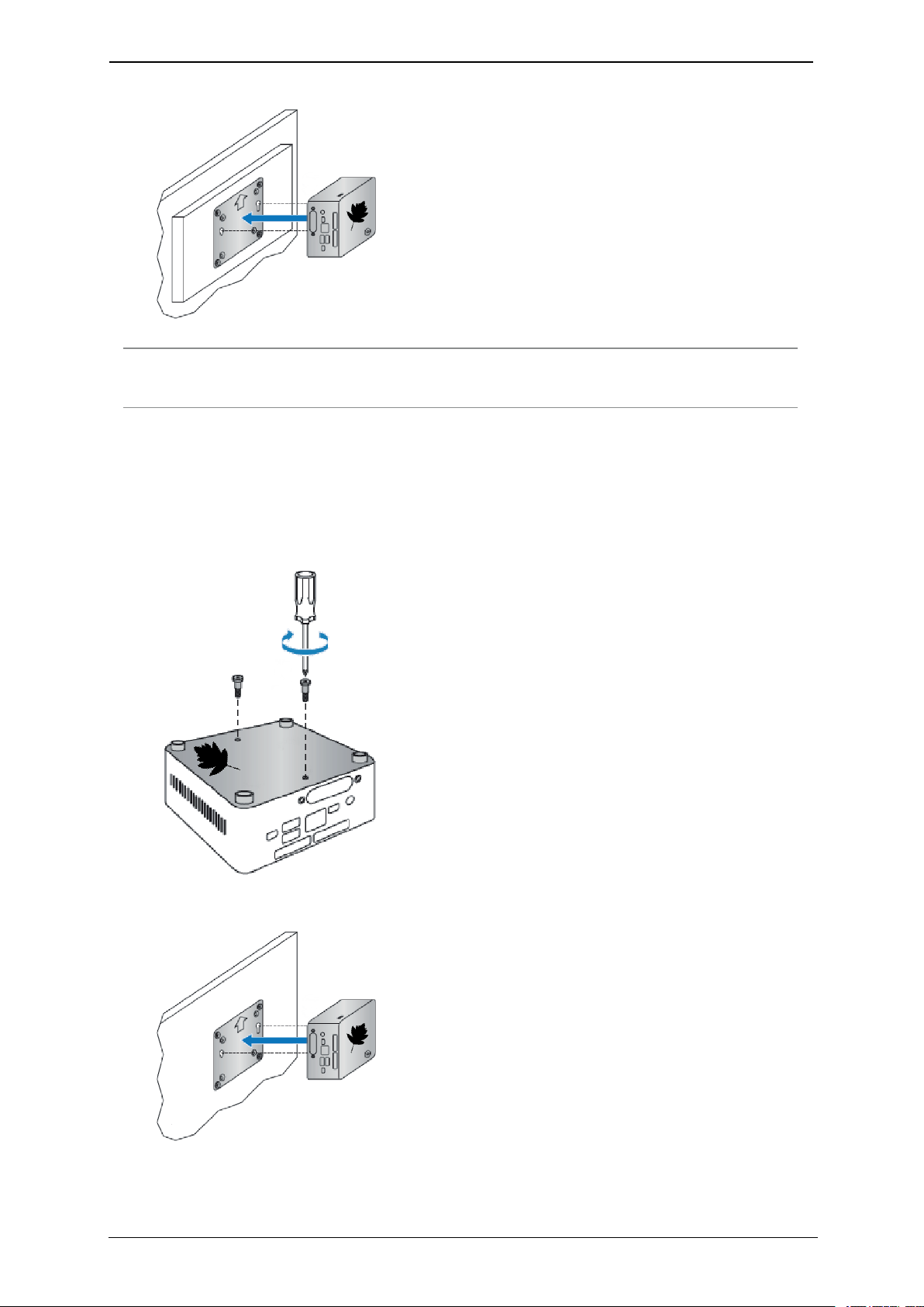
Teamline 5140 Installation Guide Page 14
Mounting the Teamline 5140 system
3. Slide the system on to the VESA mount bracket.
Note: The screws provided for mounting the bracket to displays may not fit all
models.
To attach and use the VESA bracket on a wall:
1. Use four screws and wall plugs of appropriate size and type to mount the
bracket to a wall.
2. Attach the two slightly larger black screws provided to the bottom chassis
cover of the Teamline system.
3. Slide the system on to the VESA mount bracket.

Teamline 5140 Installation Guide Page 15
Mounting the Teamline 5140 system
Mount dimensions
Teamline 5140 Installation Guide Page 16
Configuring Teamline 5140
Configuring Teamline 5140
Before you can use the Teamline system, go to the Teamline configuration
web interface to:
nEnter the Quick Connect code to connect the Teamline system to the
Maestro management platform
nConfigure a proxy server (if required)
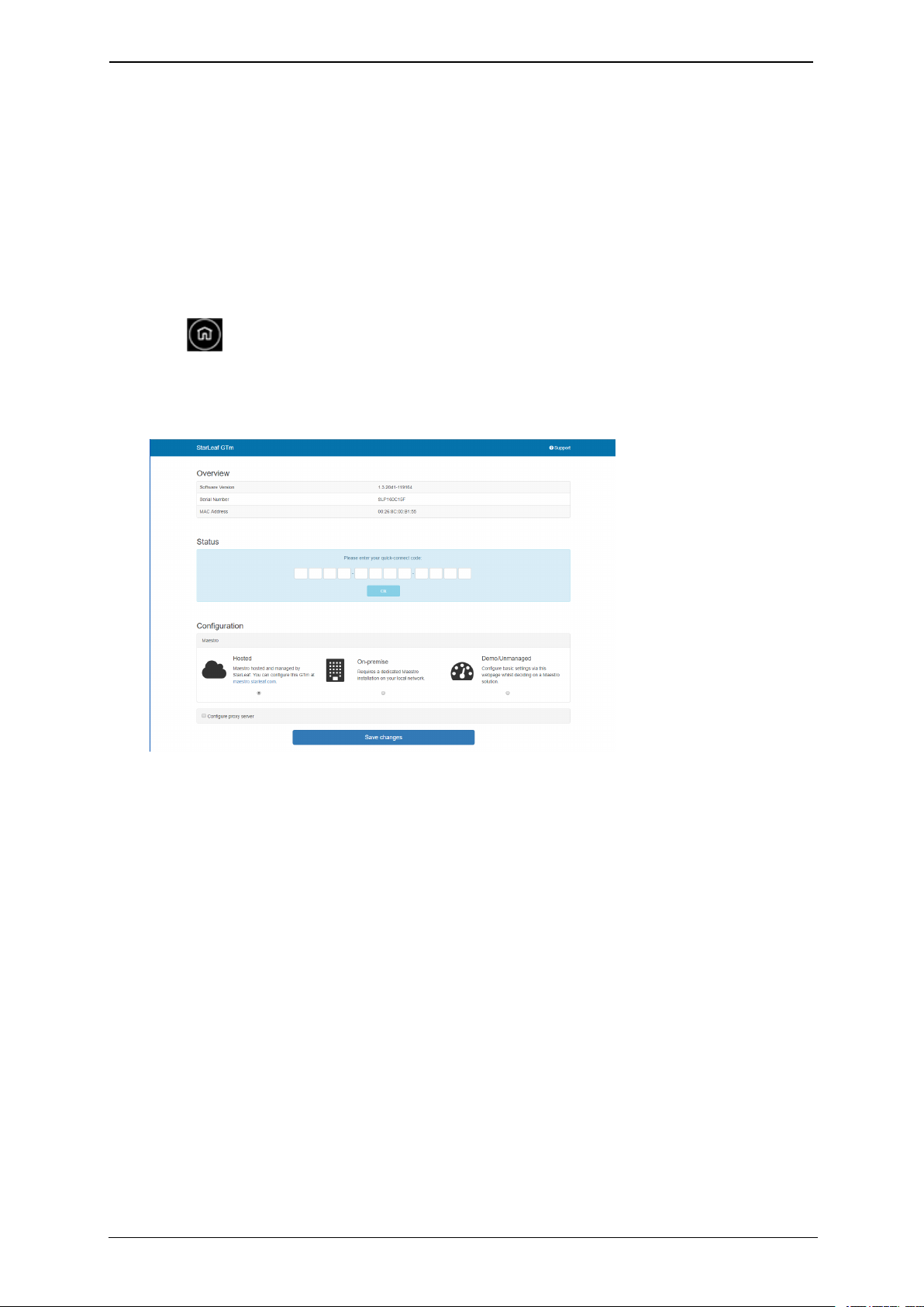
To access the configuration web interface:
1. Tap twice on the touchscreen controller to view settings, then tap
networking to view the IP address.
2. In a browser, enter this IP address in the address bar. The configuration web
interface is displayed:
3. Select Hosted if your system is managed by StarLeaf. Select On-premise if
you are using a local version of Maestro that has been installed by StarLeaf
on your local network.
Connecting the system to Maestro
To connect the Teamline system to Maestro:
1. Open the Maestro site. If you haven't created a new room for your Teamline
system, see the Maestro management platform guide on the Teamline
Knowledge Center.
2. In the Maestro Meeting Rooms page, click Manage next to the meeting
room to view the Quick Connect Code. Enter this code in the Teamline
configuration web page.
3. Click Save changes.

Teamline 5140 Installation Guide Page 17
Configuring Teamline 5140
Configuring the proxy server (optional)
Optionally, you can use the web interface to configure a proxy server:
1. If there is a proxy server for your deployment, select Configure proxy server.
2. Select Automatically detect settings or Manual configuration.
3. If you are using a setup script to configure the proxy server, enter the
location of the script in the Configuration script address field.
4. If the proxy server requires a user name and password, enter the details in
the Username and Passsword fields.
Changing system settings
To change the Teamline system configuration:
1. In the Maestro Meeting Rooms page, click Manage next to the relevant
room.
2. In the Info area, copy the unlock password.
3. In the Teamline configuration web interface, paste the password in the
Unlock field.
4. Click Unlock.
Using a static IPaddress
By default, the Teamline system uses DHCP to acquire an IP address. If
required, you can configure the system with a static IP address. In networking,
toggle DHCP off and tap to enter the IP address,netmask, and gateway
addresses.
Note: If the address entered is invalid, you are not notified on the
touchscreen. Ensure you enter the correct details.

Teamline 5140 Installation Guide Page 18
Ports and protocols
Ports and protocols
This is a list of ports and protocols used by the Teamline system. You will need
this if your network has Network Access Control (NAC) enabled, which
analyzes traffic from the unit for security purposes.
Room system connectivity
All source ports are ephemeral (1024-65535) unless otherwise specified.
Outbound
Port Host Protocol Notes
53 DNS server as defined in the network
configuration
TCP/UDP
(DNS)
Used to resolve domain
names or find services (for
example, in autodiscovery
on older configurations
using SRV or A records)
67 Broadcast
DHCP server
UDP
(DHCP)
Requests to DHCP server
443 *.maestro.starleaf.com
Local Maestro server
Note: * denotes either config or fw. If
you are using a proxy, the whitelist
should be *.maestro.starleaf.com and
maestro.starleaf.com if the first rule
doesn't cover this
TCP
(HTTPS)
Management server
connection (either hosted
or on-premise)
5355 Windows devices TCP/UDP
(LLMNR)
Used to resolve names on
the local network
Inbound
Port Host Protocol Notes
68 DHCP server UDP (DHCP) Responses from
DHCP server
80 Any TCP (HTTP) Endpoint control
API
443 Any TCP (HTTPS) Web UI
On-premise Skype for Business 2015 or Lync 2013
All source ports are ephemeral (1024-65535) unless otherwise specified.

Teamline 5140 Installation Guide Page 19
Ports and protocols
Outbound
Port Host Protocol Notes
80 lyncdiscover.domain
lyncdiscoverinternal.domain
autodiscover.domain
TCP (HTTP) Used in Lync and
EWS autodiscovery
88 AD server TCP/UDP Kerberos
authentication
443 Local webticket
ADFS wsfed servers
TCP (HTTPS) Various
authentication
modes for external
servers (also EWS
server)
3478 Edge server UDP
(STUN/MSTURN)
Used for external
user access to AV
sessions and media
(UDP)
5061 Front End server TCP (MTLS) Used for client-to-
server SIP traffic for
external user
access
1024-65535 Front end server
Other client
UDP Audio, and video
(minimum of 40
ports required)
1024-65535 Front end server
Other client
TCP Audio, video, and
application sharing
1024-65535 Front end server
Other client
TCP (PSOM) Peer-to-peer file
transfer for
conferencing file
transfer. Clients use
PSOM
Teamline systems on external networks
If the Teamline system is not located on the same local network as the Skype
for Business deployment (that is, if it connects using the Edge server), the
following ports and protocols also apply.
All source ports are ephemeral (1024-65535) unless otherwise specified.
Other manuals for Teamline 5140
1
Table of contents


