Dauphin PHONE CUBE User manual

1
https://www.kctoolco.com/hazet-863p-1-4-reversible-ratchet/
REVERSIBLE RATCHET 1/4“ DRIVE FOR
CORNER SCREWS ON TOP TRAVERSE BEAMS
ALTERNATIVE : 5MM ALLEN KEY
TOOLS REQUIRED:
HARDWARE INCLUDED:
BOTTOM FEET FILLERS
SCREWS FOR DOOR
COVERS FOR DOOR FRAME HOLES
ROOF CLIPS TO SECURE CEILING
8MM HEX BOLT SCREWS TO SECURE
PANELS TO TOP TRAVERSE
DESK KIT THREADED INSERTS
AND LOCK NUTS
TO SECURE DESK TO PANEL
RUBBER MALLET FOR INSERTING PANELS
1/8 DRILL BIT FOR DOOR HOLES
CORNER SQUARE TO ALIGN FRAME
FLAT PALLET KNIFE TO FACILITATE PANEL INSTALL
SPIRIT/LASER LEVEL TO LEVEL THE UNIT
CLAMPS TO FACILITATE PANEL INSTALL
13MM FLAT WRENCH FOR LEVELING THE GLIDES OF STRUCTURE
8MM HEX BIT WITH EXTENSION FOR HEX BOLT SCREWS
6MM ALLEN KEY FOR ROOF CLIPS
PHILLIPS HEAD BIT FOR SCREWS FOR DOOR FRAME
TWO 9 FT. STEP LADDERS FOR INSTALLING ROOF & PANELSMOVING CART/DOLLY FOR TRANSPORTING PANELS,
ROOF, AND POSTS
2
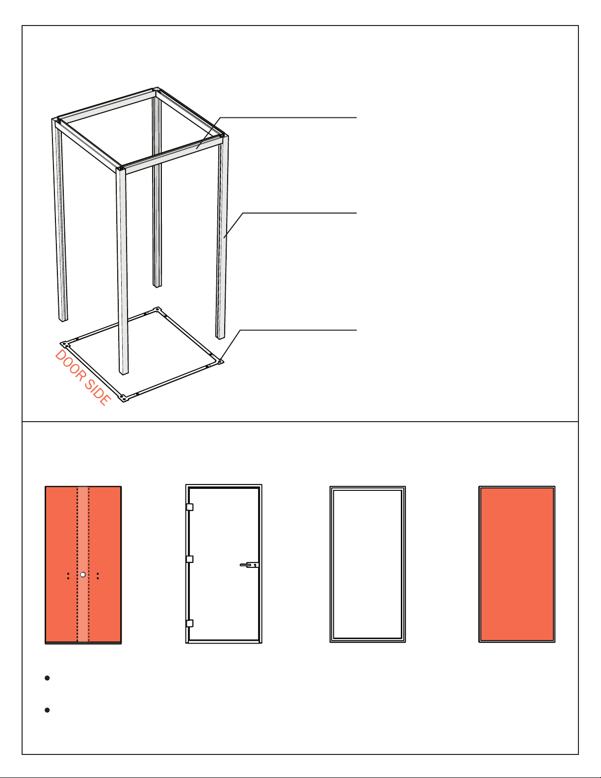
TOP TRAVERSE BEAMS
VERTICAL POSTS
SQUARE FLOOR BASE
MAIN ELEMENTS OF SKELETON FRAME:
STANDARD PHONE CUBE PANELS:
TECH ACOUSTIC PANEL
(DESK|POWER) GLASS DOOR GLASS PANEL STANDARD
ACOUSTIC PANEL
Fabric faces are applied to both sides of each Acoustic Panel
Tech Panel includes a conduit for power wiring to go through and T-nuts for the Desk installation
3
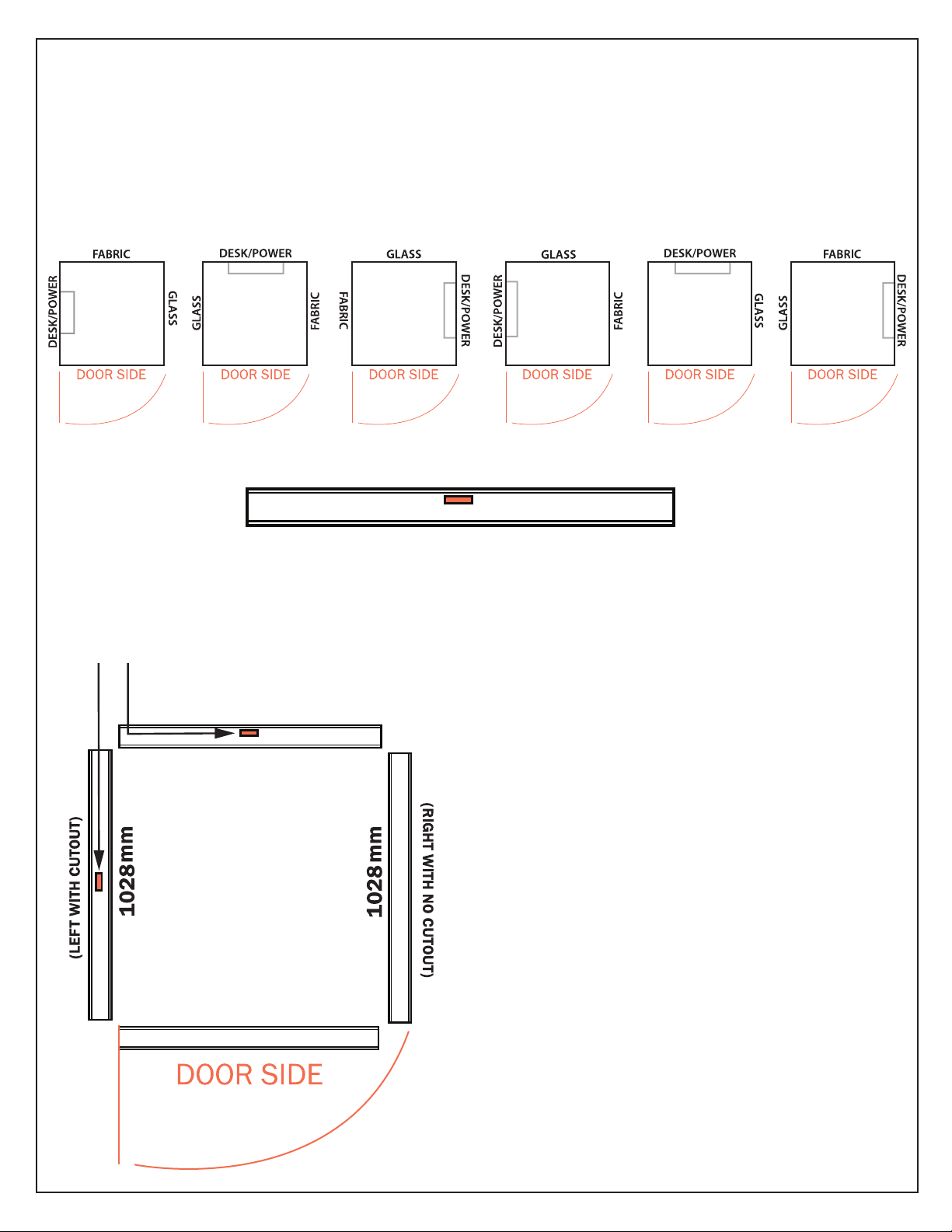
The 1026 marked beams will be installed on
the door side (Front) and opposite rear side.
Desk and Power can be installed on the rear.
The 1028 marked beams will be installed on
the sides (left and right) of the Cube. If the desk
is to be installed on the left or right, the beam
with the cut out must be installed on the
desk + power side.
One of the top traverse beams in each size (1026 and 1028) will have a cutout for power wiring to go
through this beam and the Tech panel.
The Desk and Power Tech Panel is commonly installed on the side adjacent to the door hinges (left side),
but can also be installed on the rear or the right side.
LOCATION OF THE TECH PANEL FOR DESK AND POWER
POWER CUTOUT IN TOP TRAVERSE BEAM
1026mm
1026mm
(NO CUTOUT)
(REAR WITH CUTOUT)
TRAVERSE BEAM POWER CUTOUTS

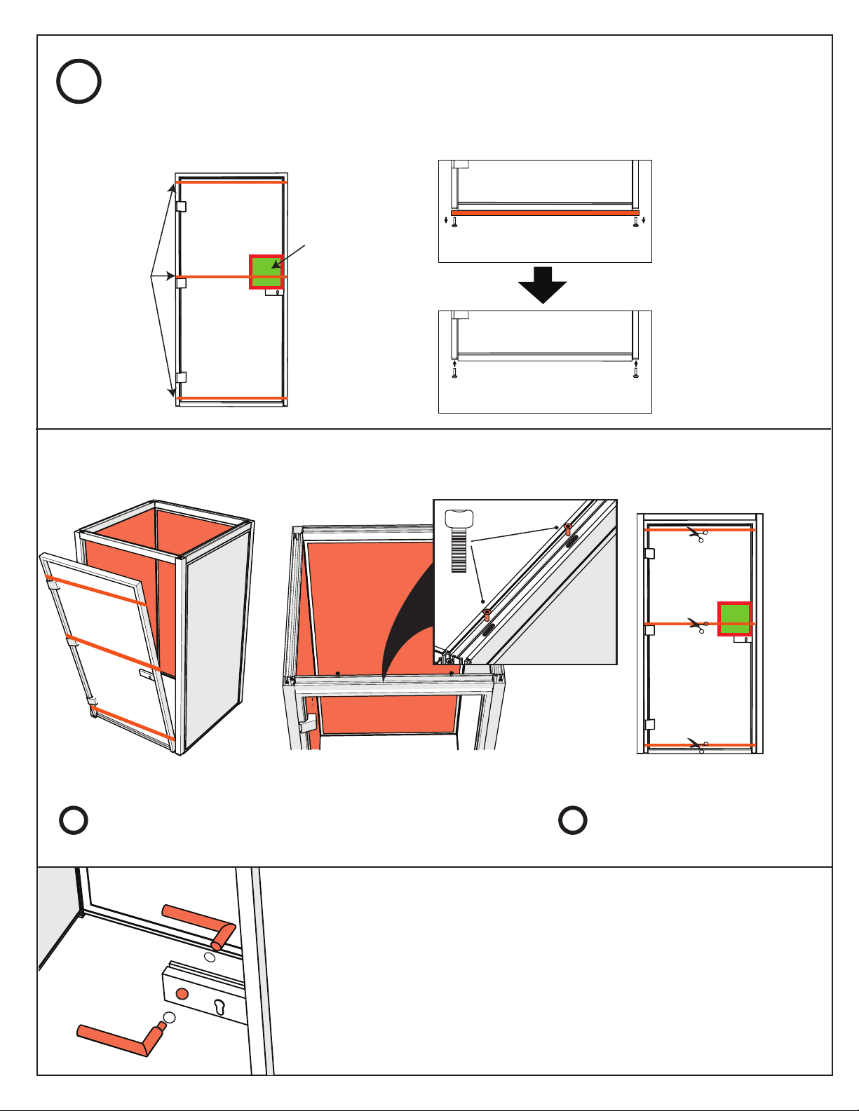
4
Assemble two parallel sides by securing vertical
posts A and Bwith a 1026mm top traverse beam as
shown above.
The TRAVERSE Beam for the DOOR PANEL must have
NO CUTOUT.
Connect the opposite goal posts using the 1028mm
beams.
ASSEMBLE THE SKELETON FRAME (DO NOT TIGHTEN SCREWS ALL THE WAY)
TOP TRAVERSE BEAMS TO VERTICAL
POSTS CONNECTION DETAIL
1
DO NOT TIGHTEN SCREWS!
Screws will be tightened firmly later
at step
B
B
A
A
A
A
B
B
TOP TRAVERSE BEAMS (TOP VIEW):
The screw
plates go IN the
vertical post.
A Ratchet with 5mm hex bit is
used to assemble the
TRAVERSE Beam.
TRAVERSE BEAM: WITH CUTOUT
TRAVERSE BEAM: NO CUTOUT

Lay down the square floor base in the exact desired location for the Telephone Cube. Ensure that the
door side is on the desired side and that the square base is placed face up, with countersink holes
facing up.
COUNTERSINK FACE UP
2LOCATE WHERE PHONE CUBE IS TO BE INSTALLED
5
The leveling glides of the Vertical
Posts go into the outer holes of the
skeleton base.
PLACE SKELETON ON FLOOR BASE & PREPARE UNIT FOR PANELS
3

6
INSTALL POWER SOURCE CABLE IN TECH PANEL IF POWER IS COMING FROM THE
FLOOR
Insert and feed the GST end of the cable up the conduit from the bottom of the panel.
DISREGARD THIS STEP IF THE POWER SOURCE IS LOCATED OUTSIDE THE CUBE
(CEILING, FLOOR OR WALL)
APPROX 33FT LONG
BOTTOM
TOP
GST
3 PIN GST
3 PIN
DISREGARD THIS STEP IF THE CONFIGURATION DOES NOT HAVE A TECH PANEL
4
7
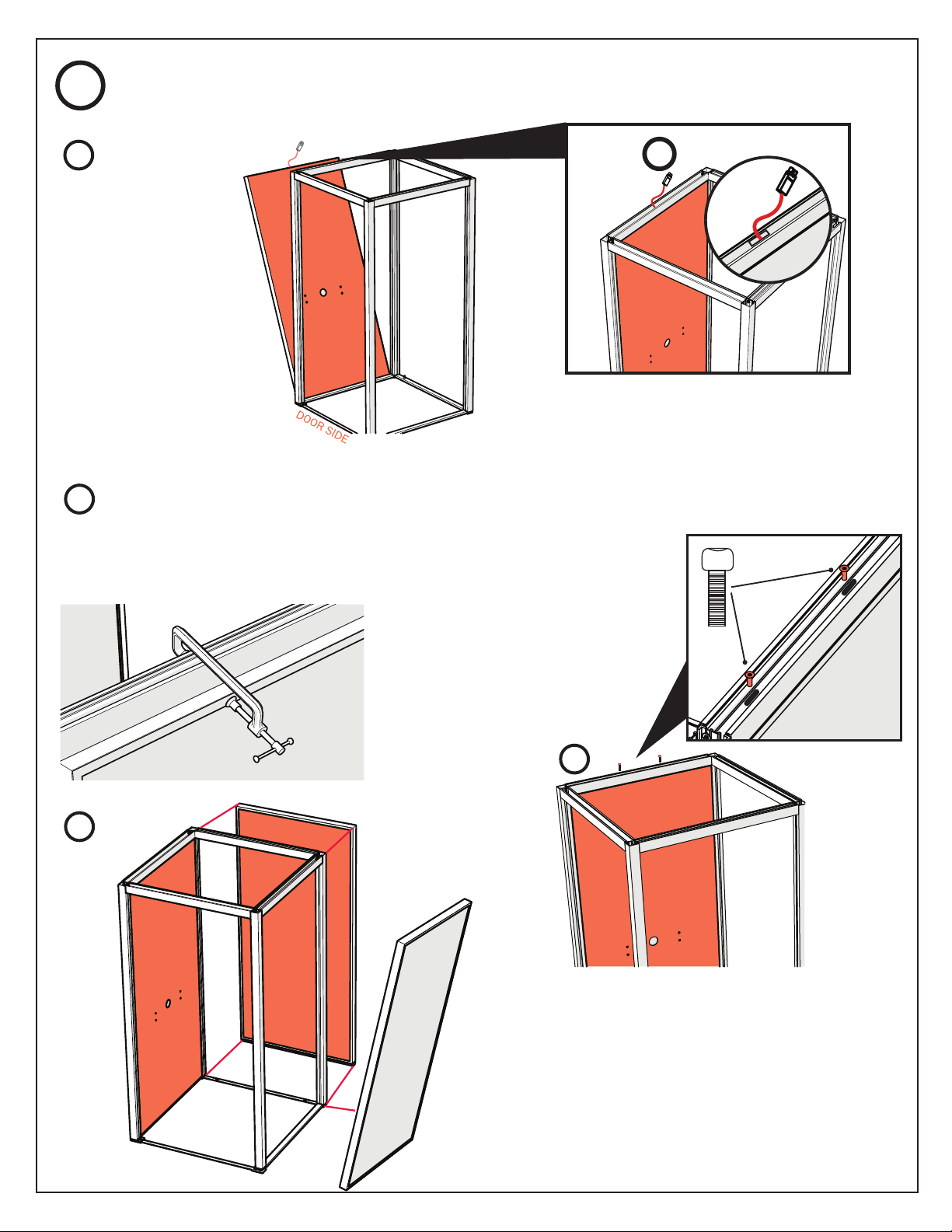
INSTALL THE PANELS INTO SKELETON FRAME
Once panel is half way inside the frame,
use a clamp on the skeleton frame and the
panel frame to facilitate the process.
If the source of power is coming from
the floor, feed the GST cable through
the top traverse beam’s power cutout.
4
5
PER STEP
Insert the Tech Panel
from the bottom on an
angle, then fit the
sides and top into the
skeleton frame. Use a
flat pallet knife.
Install and tighten the screws to hold the
panel within the skeleton frame.
USE 8MM HEX BIT
WITH EXTENSION
1
2
3
4
Repeat these for all Panels.
INSTALL POWER SOURCE CABLE IN TECH PANEL IF POWER IS COMING FROM THE
FLOOR
8
Install the door handles onto the door. Ensure the handles are
positioned as pictured facing the front of the glass door.
Check that the door latch clicks when closing the door.
Install the door panel. Secure the door frame with two
hex bolt screws as previously done with the other panels.
PREPARE AND INSTALL THE DOOR
INSTALL THE PANELS INTO SKELETON FRAME 6
The door
handle
package will
be attached to
the glass door.
12Cut & take out the plastic strips
once the door frame is installed.
Black Plastic
Strips:
They keep the
door glass panel
in the door
frame during
assembly.
USE 8MM HEX BIT
WITH EXTENSION
1. Remove the
protective piece of
wood from the
bottom of the door
carefully by removing
both leveling glides.
2. Install the leveling
glides back onto the
door when finished.
Preparing the Door Panel
Installing the Door Panel
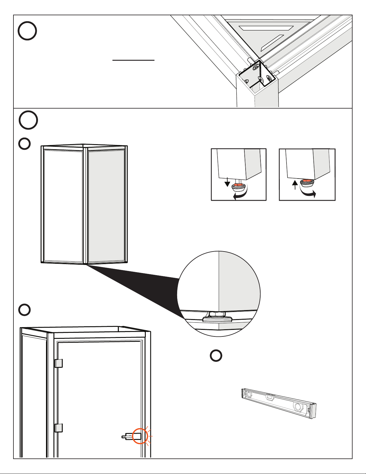
9
Adjust the Panel leveling glides and
Vertical Post leveling glides to ensure
that the whole structure is leveled in
all directions.
Close the door before leveling (until it
clicks).
Square all corners and firmly tighten all of the
corner screws and hex bolts located on top of
the panels and door. Check that diagonal
measurements from the inside are equal all
around.
8FINAL LEVELING OF STRUCTURE
ENSURE UNIT IS SQUARED/TIGHTEN
THE BOLTS
7
Make sure all glides are in
their respective holes before
leveling the structure.
IMPORTANT:
1
2
3
Leveling the unit from a flat stance
minimizes the amount of open space
between floor and posts/panels.
(IMPORTANT FOR ACOUSTICS).
Click
Use the 13mm Flat Wrench to
loosen/tighten the leveling glides
Adjusting Leveling Glides:
Loosening Leveling
Glide
Tightening Leveling
Glide
Loosening the
leveling glides will
RAISE the post.
Tightening the
leveling glides will
LOWER the post.

10
- Check the Glass Door Panel to make sure it’s not slanted
(The gap between Glass Door and Door Frame should be
approximately 1/4”).
There are 3 holes on the door frame as highlighted in the images above. For each hole,
drill a 1/8th inch pilot hole through the center of the hole, through the vertical post of the
skeleton frame, and install the screws provided. Cover the holes with the provided covers.
Ensure that the door does not swing out too hard or too fast after installing the screws.
Test the door latch again after installing these screws and ensure it clicks when closing
the door.
x3
SECURE THE DOOR PANEL (UNIT HAS TO BE LEVELED BEFORE THIS STEP)
9
4
8FINAL LEVELING OF STRUCTURE Cont.
Correctly Leveled Glass Door
Panel
Incorrectly Leveled Glass Door
Panel
- Check if there is any scraping between the glass door
panel and floor when opening and closing the door (there
should not be any scraping).
Test Glass Door Panel:
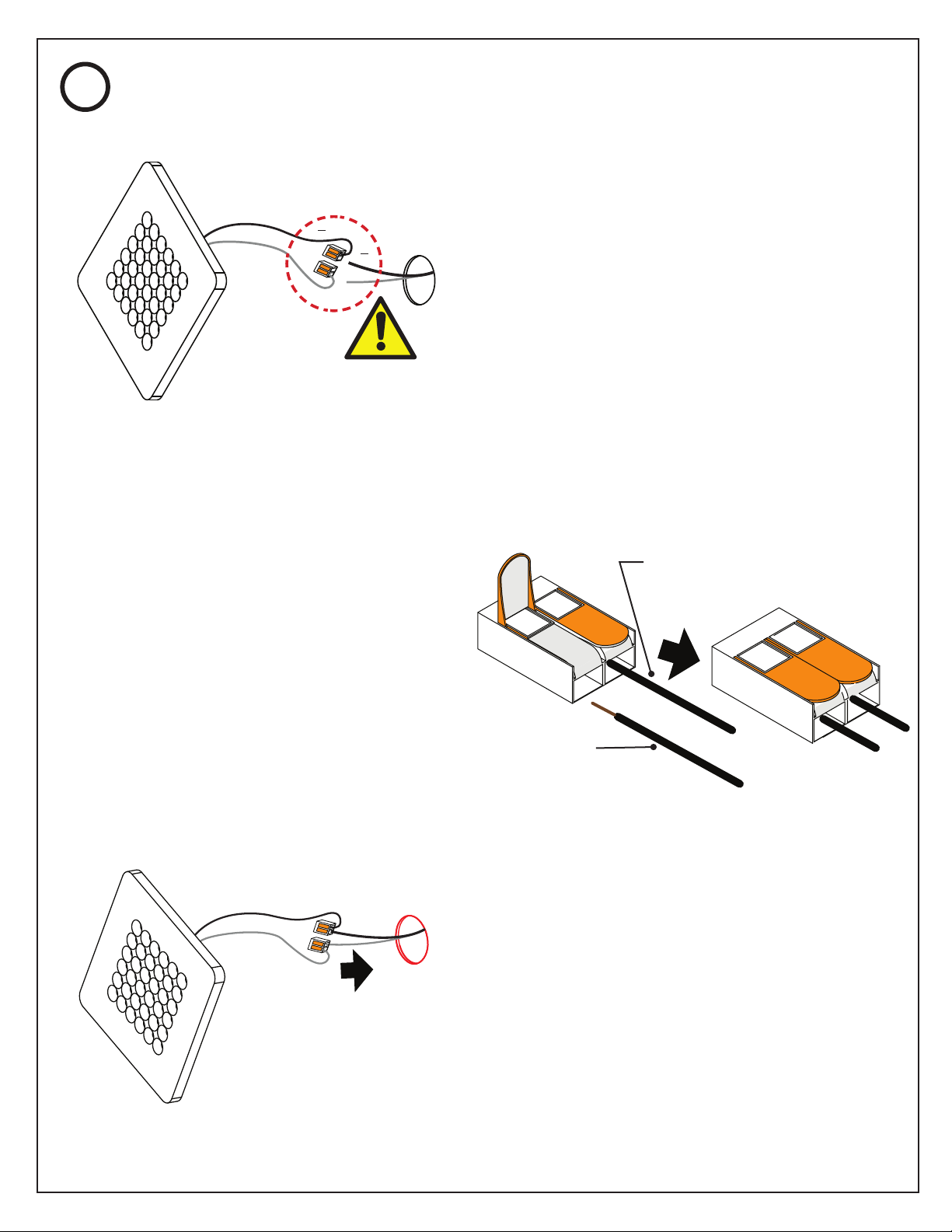
11
Before installing the roof onto the unit,
connect the two wires coming out of the
interior of the ceiling panel to the respective
wires connected to the LED light. Ensure to
the correct polarity of the connections made.
To properly connect lift the orange tab back
to open the track, then insert and push the
cable into the track all the way in. Secure
the connection by pushing the tab back
down. Ensure you connect the same polar
wires to each of these components.
Insert the connected wiring into the hole so the
LED light can lay flushed against the ceiling.
Place the LED light on the ceiling and center unit
with the hole.
CONNECT LED LIGHT TO CEILINGS
10
CAUTION:
Ensure correct
polarity!
White= Positive
Black/Brown/Red = Negative
Ceiling
negative wire
LED negative wire
(already connected)
+
24 V DC
+
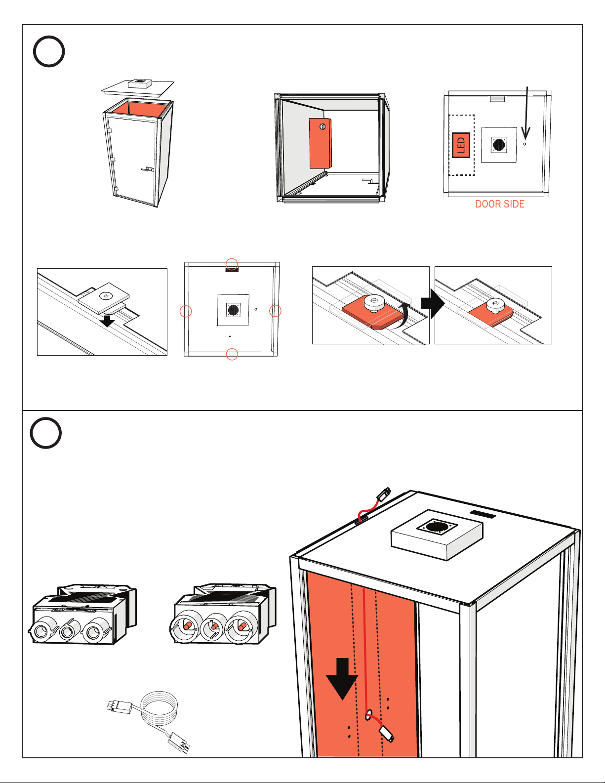
12
The LED light should be directly above the desk and power,
with the motion sensor on the opposite side.
Turn the lower part 90 degrees with your finger
and then tighten the screw in order to secure the
roof.
Insert Roof Clips into the top traverse beams in
the locations circled in the image to the right.
Feed the FEMALE GST end of the cable from the
top down through the cutout of the top traverse
beam into the conduit and out of the hole in the
tech panel.
GST TO GST 6FT CABLE
MALE GST
FEMALE GST
INSTALL WIRING FOR DESK POWER IN TECH PANEL
INSTALL THE ROOF
11
12
Place the roof on top of the structure.
Occupancy Sensor
MALE GSTFEMALE GST

13
Insert and install the power unit on to the
surface of the desk through the grommet
hole. Connect the GST cable from the power
unit with the GST cable from the panel.
Secure with lock nuts provided.
Screw the threaded rods provided in the
Desk Kit into the tech panel.
Install the desk onto the threaded rods on
the tech panel.
INSTALL DESK ONTO TECH PANEL
13
INSTALL POWER UNIT IN DESK
14

14
Connect the desk|power, source, and ventilation system GST cables into the GST Triple
tap extension.
3 PIN
IF POWER FROM
THE FLOOR
IF POWER FROM
THE CEILING
DESK/POWER
(MALE)
(MALE)
(FEMALE)
POWER SOURCE
VENTILATION SYSTEM
GST TRIPLE TAP EXTENSION
CONNECT ALL WIRING
15
3 PIN
Female GST
Phone Cube
Control Box
3-Pronged
Plug
Connect to Power Source
Desk Power Desk Power
Connect
to
Power
Source

15
Insert the square shaped foam fillers into the space between the base and the bottom of the
vertical posts. Then, insert the smaller rectangular pair onto each side of the bottom of the door
frame. Some irregular floors might require foam filler strips under all 3 panels with exception of
the door.
16
USA: 100 Fulton Street Boonton, NJ 07005 TEL: 800.631.1186 FAX: 800.220.3844 EMAIL: [email protected] WEB: dauphin.com CB1x1.02.15.19
Other manuals for PHONE CUBE
1
Table of contents
Other Dauphin Office Equipment manuals


