manuals.online logo
Brands
  1. Home
  2. •
  3. Brands
  4. •
  5. Tektronix
  6. •
  7. Test Equipment
  8. •
  9. Tektronix TBS2000 Series Setup guide

Tektronix TBS2000 Series Setup guide

xx
Contacting Tektronix
Tektronix, Inc., 14150 SW Karl Braun Drive, P.O. Box 500,
Beaverton, OR 97077, USA
For product information, sales, service, and technical support:
In North America, call 1-800-833-9200.
Worldwide, visit www.tek.com to find contacts in your area.
Important safety information
This manual contains information and warnings that must be
followed by the user for safe operation and to keep the product
in a safe condition. To safely perform service on this product,
additional information is provided at the end of this section.
General safety summary
Use the product only as specified. Review the following safety
precautions to avoid injury and prevent damage to this product
or any products connected to it. Carefully read all instructions.
Retain these instructions for future reference.
Comply with local and national safety codes.
For correct and safe operation of the product, it is essential that
you follow generally accepted safety procedures in addition to
the safety precautions specified in this manual.
The product is designed to be used by trained personnel only.
Only qualified personnel who are aware of the hazards involved
should remove the cover for repair, maintenance, or adjustment.
Before use, always check the product with a known source to
be sure it is operating correctly.
This product is not intended for detection of hazardous voltages.
Use personal protective equipment to prevent shock and arc
blast injury where hazardous live conductors are exposed.
While using this product, you may need to access other parts
of a larger system. Read the safety sections of the other
component manuals for warnings and cautions related to
operating the system.
When incorporating this equipment into a system, the safety of
that system is the responsibility of the assembler of the system.
To avoid fire or personal injury
Use proper power cord. Use only the power cord specified for
this product and certified for the country of use.
Do not use the provided power cord for other products.
Ground the product. This product is grounded through the
grounding conductor of the power cord. To avoid electric
shock, the grounding conductor must be connected to earth
ground. Before making connections to the input or output
terminals of the product, ensure that the product is properly
grounded.
Do not disable the power cord grounding connection.
Power disconnect. The power cord disconnects the product
from the power source. See instructions for the location. Do
not position the equipment so that it is difficult to access the
power cord; it must remain accessible to the user at all times to
allow for quick disconnection if needed.
Connect and disconnect properly. Do not connect or disconnect
probes or test leads while they are connected to a voltage
source.
Use only insulated voltage probes, test leads, and adapters
supplied with the product, or indicated by Tektronix to be
suitable for the product.
Observe all terminal ratings. To avoid fire or shock hazard,
observe all ratings and markings on the product. Consult the
product manual for further ratings information before making
connections to the product. Do not exceed the Measurement
Category (CAT) rating and voltage or current rating of the
lowest rated individual component of a product, probe, or
accessory. Use caution when using 1:1 test leads because the
probe tip voltage is directly transmitted to the product.
Do not apply a potential to any terminal, including the common
terminal, that exceeds the maximum rating of that terminal.
Do not float the common terminal above the rated voltage for
that terminal.
Do not operate without covers. Do not operate this product with
covers or panels removed, or with the case open. Hazardous
voltage exposure is possible.
Avoid exposed circuitry. Do not touch exposed connections
and components when power is present.
Do not operate with suspected failures. If you suspect that
there is damage to this product, have it inspected by qualified
service personnel.
Disable the product if it is damaged, Do not use the product if it
is damaged or operates incorrectly. If in doubt about safety of
the product, turn it off and disconnect the power cord. Clearly
mark the product to prevent its further operation.
Before use, inspect voltage probes, test leads, and accessories
for mechanical damage and replace when damaged. Do not use
probes or test leads if they are damaged, if there is exposed
metal, or if a wear indicator shows.
Examine the exterior of the product before you use it. Look
for cracks or missing pieces.
Use only specified replacement parts.
Do not operate in wet/damp conditions. Be aware that
condensation may occur if a unit is moved from a cold to a
warm environment.
Do not operate in an explosive atmosphere.
Keep product surfaces clean and dry. Remove the input signals
before you clean the product.
Provide proper ventilation. To ensure proper cooling, keep the
sides and rear of the instrument clear of obstructions. Slots
and openings are provided for ventilation and should never
be covered or otherwise obstructed. Do not push objects into
any of the openings.
Provide a safe working environment. Always place the product
in a location convenient for viewing the display and indicators.
Avoid improper or prolonged use of button pads. Be sure your
work area meets applicable ergonomic standards.
Probes and test leads
Before connecting probes or test leads, connect the power cord
from the power connector to a properly grounded power outlet.
Keep fingers behind the finger guards on the probes.
Remove all probes, test leads and accessories that are not in use.
Use only correct Measurement Category (CAT), voltage,
temperature, altitude, and amperage rated probes, test leads,
and adapters for any measurement.
Beware of high voltages. Understand the voltage ratings for
the probe you are using and do not exceed those ratings. Two
ratings are important to know and understand:
The maximum measurement voltage from the probe tip
to the probe reference lead
The maximum floating voltage from the probe reference
lead to earth ground
These two voltage ratings depend on the probe and your
application. Refer to the Specifications section of the manual
for more information.
WARNING. To prevent electrical shock, do not exceed the
maximum measurement or maximum floating voltage for
the oscilloscope input BNC connector, probe tip, or probe
reference lead.
Connect and disconnect properly. Connect the probe output
to the measurement product before connecting the probe
to the circuit under test. Connect the probe reference lead
to the circuit under test before connecting the probe input.
Disconnect the probe input and the probe reference lead from
the circuit under test before disconnecting the probe from the
measurement product.
Connect and disconnect properly. De-energize the circuit under
test before connecting or disconnecting the current probe.
Connect the probe reference lead to earth ground only.
Do not connect a current probe to any wire that carries voltages
above the current probe voltage rating.
Inspect the probe and accessories. Before each use, inspect
probe and accessories for damage (cuts, tears, or defects in
the probe body, accessories, or cable jacket). Do not use if
damaged.
Service safety summary
The Service safety summary section contains additional
information required to safely perform service on the product.
Only qualified personnel should perform service procedures.
Read this Service safety summary and the General safety
summary before performing any service procedures.
To avoid electric shock. Do not touch exposed connections.
Do not service alone. Do not perform internal service or
adjustments of this product unless another person capable of
rendering first aid and resuscitation is present.
Disconnect power. To avoid electric shock, switch off the
product power and disconnect the power cord from the mains
power before removing any covers or panels, or opening the
case for servicing.
Use care when servicing with power on. Dangerous voltages
or currents may exist in this product. Disconnect power,
remove battery (if applicable), and disconnect test leads
before removing protective panels, soldering, or replacing
components.
Verify safety after repair. Always recheck ground continuity
and mains dielectric strength after performing a repair.
Terms in product manuals
These terms may appear in the product manuals:
WARNING. Warning statements identify conditions or
practices that could result in injury or loss of life.
CAUTION. Caution statements identify conditions or
practices that could result in damage to this product or
other property.
Symbols and terms on the product
These terms may appear on the product:
DANGER indicates an injury hazard immediately
accessible as you read the marking.
WARNING indicates an injury hazard not immediately
accessible as you read the marking.
CAUTION indicates a hazard to property including the
product.
When this symbol is marked on the product, be
sure to consult the manual to find out the nature of
the potential hazards and any actions which have
to be taken to avoid them. (This symbol may also
be used to refer the user to ratings in the manual.)
The following symbol(s) may appear on the product:
ZZZ
TBS2000X Series Oscilloscopes
Safety and Installation
Instructions
x
*P071375900*
071-3759-00
Operating requirements
Environment requirements
Characteristic Description
Operating
temperature
0°Cto+50°C,with5°C/minutemaximum
gradient, noncondensing (NC), up to
3000 meter altitude
Operating
humidity
5% to 95% relative humidity (% RH) up to
+30 °C
5% to 60% RH above +30 °C up to +50 °C, NC
Operating
altitude
Up to 3000 meters (9842 feet)
Power requirements
Characteristic Description
Power source
voltage
100 VAC –240V
AC ±10% RMS, single phase
Power source
frequency
50/60 Hz over entire source voltage range
400 Hz (360 Hz to 440 Hz) for 115 VAC
(100 VAC–132 VAC) RMS source voltage range
Power
consumption
All models: 80 W maximum
Installation
Power on the unit
Connect the supplied power cord to the rear-panel power
connector. Push the front panel power button to power the
oscilloscope on and off. To completely remove power from the
unit, disconnect the power cord.
Controls and connections
Read the TBS2000X Series User Manual for detailed
information about all product controls, the user interface, how
to take measurements, and warranty information. The manual
is available in the languages listed below.
Language Tektronix part number
Simplified Chinese 077-1700-00
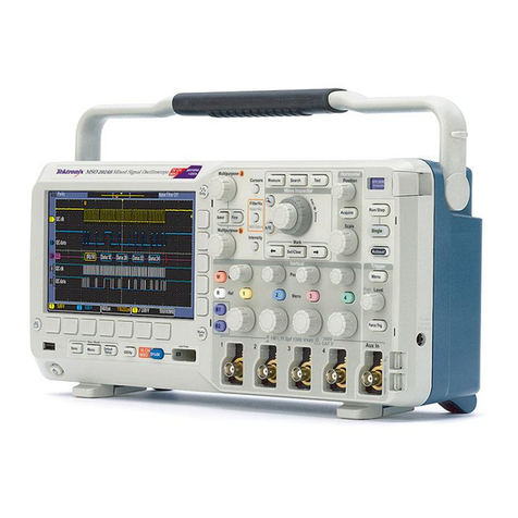
Front panel
NOTE. Some control and connector positions are different
between the two- and four-channel models, but their functions
are the same.
1. Use the Navigation controls to select menu items, set
values, display and move cursors, magnify a section of the
waveform and add marks (tags) to a waveform record. The
Mark functions are not now enabled, but will be available
in a future software update.
2. Use the Resource controls to open menus to select and
display automated measurements; save or recall setups,
waveforms, and screen images; set UI language, date and
time, network and Wi-Fi settings, and more.
3. Use the Trigger controls to set the trigger type, source
channel, trigger signal coupling, the signal’s trigger slope
(positive or negative), trigger level, and more.
4. Use the Horizontal controls to set the acquisition mode,
waveform record length, horizontal scale (time per major
horizontal graticule and samples/second), and more.
5. Use the USB 2.0 Host port to insert a USB flash drive to
save and recall screen images, waveforms, and settings,
and install new oscilloscope firmware.
6. Use the TekVPI®probe input connectors to connect the
oscilloscope to the signal. The maximum measurement
input voltage is 300 VRMS,CATII.
Asymbol next to a measurement readout indicates a
signal over range condition (clipping). This is often caused
by waveforms that extend above or below the screen edge.
To get an accurate measurement readout, adjust the vertical
scale and/or position knob to show the entire waveform
on the screen.
7. Use the Vert ical controls to select a waveform to display,
open menus to set signal coupling, bandwidth, probe
attenuation and type; move the waveform up or down on
the screen; set the vertical scale factor (volts per vertical
graticule division); and more.
Rear panel
1. Aux Out. Sends a low to high transition when a trigger
occurs, to synchronize other test equipment.
2. LAN. Connects to a 10/100 Base-T local area network for
remote access.
3. USB (Host). Connects to the optional Wi-Fi adapter for
wireless remote access.
4. USB (Device). Connects to a PC for remote control using
USBTMC protocol.
Cleaning
Use a dry, soft cotton cloth to clean the outside of the unit.
Do not use any liquid cleaning agents or chemicals that could
damage the case, controls, screen, markings or labels, or
possibly infiltrate the case.
Compliance
This section lists the EMC (electromagnetic compliance),
safety, and environmental standards with which the instrument
complies. This product is intended for use by professional and
trained personnel only; it is not designed for use in households
or by children.
Questions about he following compliance information may be
directed to the following address:
Tektronix, Inc.
PO Box 500, MS 19‐045
Beaverton, OR 97077, USA
www.tek.com
EMC compliance
EC declaration of conformity – EMC
Meets intent of Directive 2014/30/EC for Electromagnetic
Compatibility. Compliance was demonstrated to the following
specifications as listed in the Official Journal of the European
Communities:
EN 61326-1, EN 61326-2-1. EMC requirements for electrical
equipment for measurement, control, and laboratory use. 123
45
CISPR 11 (Group 1, Class A)
IEC 61000-4-2; IEC 61000-4-3; IEC 61000-4-4;
IEC 61000-4-5; IEC 61000-4-6; IEC 61000-4-11
EN 61000-3-2:A1/A2; EN 61000-3-3
1This product is intended for use in nonresidential areas only. Use in residential
areas may cause electromagnetic interference.
2Emissions that exceed the levels required by this standard may occur when
this equipment is connected to a test object.
3Equipment may not meet the immunity requirements of applicable listed
standards when test leads and/or test probes are connected.
4For compliance with the EMC standards listed here, high quality shielded
interface cables that incorporate low impedance connection between the cable
shield and the connector shell should be used.
510 mV/division to 1 V/division: ≤1.0 division waveform displacement or
≤2.0 division increase in peak-to-peak noise is allowed when the instrument
is subjected to fields and signals as defined in the IEC 61000-4-3 and
IEC 61000-4-6 tests.
Australia / New Zealand declaration of conformity – EMC
Complies with the EMC provision of the Radiocommunications
Act per the following standard, in accordance with ACMA:
CISPR 11. Radiated and Conducted Emissions, Group
1, Class A, in accordance with EN 61326-1 and EN
61326-2-1.
Safety compliance
This section lists the safety standards with which the product
complies and other safety compliance information.
EC declaration of conformity – low voltage
Compliance was demonstrated to the following specification as
listed in the Official Journal of the European Union:
Low Voltage Directive 2014/35/EU.
EN 61010-1; EN 61010-2-030
U.S. nationally recognized testing laboratory listing
UL 61010-1; UL 61010-2-030
Canadian certification
CAN/CSA-C22.2 No. 61010-1; CAN/CSA-C22.2 No.
61010-2-030
Additional compliances
IEC 61010-1; IEC 61010-2-030
Equipmenttype
Test and measuring equipment.
Safety class
Class 1 - grounded product.
Pollution degree rating
Pollution Degree 2 (as defined in IEC 61010-1). Rated for
indoor, dry location use only.
Measurement and overvoltage category descriptions
Measurement terminals on this product may be rated for
measuring mains voltages from one or more of the following
categories (see specific ratings marked on the product and in
the manual).
Category II. Circuits directly connected to the building wiring
at utilization points (socket outlets and similar points).
NOTE. Only measurement circuits have a measurement
category rating. Only mains power supply circuits have an
overvoltage category rating. Other circuits within the product
do not have either rating.
Mains overvoltage category rating
Overvoltage category II (as defined in IEC 61010-1).
Environmental considerations
This section provides information about the environmental
impact of the product.
Restriction of hazardous substances
Complies with RoHS2 Directive 2011/65/EU.
Product end-of-life handling
Observe the following guidelines when recycling an instrument
or component:
Equipment recycling. Production of this equipment required
the extraction and use of natural resources. The equipment may
contain substances that could be harmful to the environment or
human health if improperly handled at the product’s end of life.
To avoid release of such substances into the environment and
to reduce the use of natural resources, we encourage you to
recycle this product in an appropriate system that will ensure
that most of the materials are reused or recycled appropriately.
This symbol indicates that this product complies
with the applicable European Union requirements
according to Directives 2012/19/EU and
2006/66/EC on waste electrical and electronic
equipment (WEEE) and batteries. For information
about recycling options, check the Tektronix Web
site (www.tek.com/productrecycling).
Copyright © Tektronix, Inc. All rights reserved. www.tek.com
FCC – EMC
Emissions are within the limits of FCC 47 CFR, Part 15,
Subpart B for Class A equipment.
xx
Tektronix 联系信息
Tektronix, Inc., 14150 SW Karl Braun Drive, P.O. Box
500, Beaverton, OR 97077, USA
有关产品信息、销售、服务和技术支持:
在北美地区,请拨打 1-800-833-9200。
其他地区用户请访问 www.tek.com 查找当地的联系信
息。
重要安全信息
本手册包含用户必须遵守的信息和警告,以确保安全操作
并保证产品安全。为保证安全地对本产品进行维修,本部
分结尾还提供其他信息。
常规安全概要
请务必按照规定使用产品。详细阅读下列安全性预防措
施,以避免人身伤害,并防止损坏本产品或与本产品连接
的任何产品。认真阅读所有说明。保留这些说明以备将来
参考。
遵守当地和国家安全法令。
为了保证正确安全地操作产品,除本手册规定的安全性预
防措施外,您还必须遵守普遍公认的安全规程。
产品仅限经过培训的人员使用。
只有了解相关危险的合格人员才能进行开盖维修、保养或
调整。
使用前,请务必检查产品是否来自已知来源,以确保正确
操作。
本产品不适用于检测危险电压。
如果有危险的带电导体暴露,请使用个人保护装备以防电
击和强电弧伤害。
使用本产品时,您可能需要使用一套大型系统的其他部
件。有关操作这类系统的警告和注意事项,请阅读其他组
件手册的安全性部分。
将本设备集成到某系统时,该系统的安全性由系统的组装
者负责。
避免火灾或人身伤害
使用合适的电源线: 只能使用本产品专用并经所在国家/
地区认证的电源线。
不要使用为其他产品提供的电源线。
将产品接地: 本产品通过电源线的接地导线接地。为避免
电击,必须将接地导线与大地相连。在对本产品的输入端
或输出端进行连接之前,请务必将本产品正确接地。
不要切断电源线的接地连接。
断开电源: 电源线可以使产品断开电源。请参阅有关位置
的说明。请勿将设备放在难以接近电源线的位置;必须保
证用户可以随时操作电源线,以在需要时快速断开连接。
正确连接并正确断开连接: 探头或测试导线连接到电压源
时请勿插拔。
仅使用产品附带的或 Tektronix 指明适合产品使用的绝
缘电压探头、测试导线和适配器。
遵守所有终端额定值: 为避免火灾或电击危险,请遵守产
品上所有的额定值和标记说明。在连接产品之前,请先查
看产品手册,了解额定值的详细信息。不要超过本产品、
探头或附件中各组件的额定值最低的测量类别 (CAT) 额
定值和电压或电流额定值。在使用 1:1 测试导线时要小
心,因为探头端部电压会直接传输到产品上。
对任何终端(包括公共终端)施加的电压不要超过该终端
的最大额定值。
请勿将公共终端浮动到该终端的额定电压以上。
切勿开盖操作: 请勿在外盖或面板拆除或机壳打开的状态
下操作本产品。可能有危险电压暴露。
远离外露电路: 电源接通后请勿接触外露的接头和元件。
怀疑产品出现故障时,请勿进行操作: 如果怀疑本产品已
损坏,请让合格的维修人员进行检查。
产品损坏后请弃用。如果损坏或者工作不正常,请勿使
用。如果怀疑产品存在安全问题,请关闭产品并断开电源
线。并做清晰标记以防其再被使用。
在使用之前,请检查电压探头、测试导线和附件是否有机
械损坏,如损坏则予以更换。如果探头或测试导线损坏、
金属外露或出现磨损迹象,请勿使用。
在使用之前请先检查产品外表面。查看是否有裂纹或缺失
部件。
仅使用规定的替换部件。
请勿在潮湿环境下操作: 请注意,如果某个单元从冷处移
到暖处,则可能发生凝结情况。
请勿在易燃易爆的环境下操作:
请保持产品表面清洁干燥: 清洁本产品前,请移除输入信
号。
请适当通风: 为确保正常散热,请不要在仪器两侧和后面
堆放物品。所提供的狭槽和开口用于通风,不得遮盖或阻
挡。请勿将物体放进任何开口。
提供安全的工作环境: 始终将产品放在方便查看显示器和
指示器的地方。避免对按钮盘的不当或长时间使用。请确
保工作区符合适用的人体工程学标准。
探头和测试导线
连接探头或测试导线之前,请将电源线从电源连接器连接
到正确接地的电源插座。
请将手指放在探头上手指防护装置的后面。
拔掉所有不用的探头、测试导线和附件。
仅使用正确的测量类别 (CAT)、电压、温度、海拔高度和
电流额定的探头、导线和适配器进行测量。
小心高电压: 了解您正在使用的探头的额定电压,请不要
超出这些额定值。重要的是知道并理解两个额定值:
探头端部到探头参考引线的最大测量电压
探头参考导线到大地的最大浮动电压。
这两个额定电压取决于探头和您的应用。请参阅手册的
“技术规格”部分了解更多详情。
警告: 为防止电击,请不要超出示波器输入 BNC 连
接器、探头端部或探头参考导线的最大测量电压或最
大浮动电压。
正确连接并正确断开连接: 将探头连接到被测电路之前,
先将探头输出端连接到测量产品。在连接探头输入端之
前,请先将探头参考导线与被测电路连接。将探头与测量
产品断开之前,请先将探头输入端及探头参考导线与被测
电路断开。
正确连接并正确断开连接: 连接电流探头或断开电流探头
的连接之前请先将被测电路断电。
只能将探头参考导线连接到大地。
不要将电流探头连接到电压超过电流探头的电压额定值的
任何导线。
检查探头和附件: 在每次使用之前,请检查探头和附件是
否损坏(探头本体、附件、电缆外壳等的割裂、破损、缺
陷)。如果损坏,请勿使用。
维修安全概要
维修安全概要部分包含安全执行维修所需的其他信息。
只有合格人员才能执行维修程序。在执行任何维修程序之
前,请阅读此维修安全概要和常规安全概要。
避免电击: 接通电源时,请勿触摸外露的连接。
不要单独维修: 除非现场有他人可以提供急救和复苏措
施,否则请勿对本产品进行内部维修或调整。
断开电源: 为避免电击,请先关闭仪器电源并断开与市电
电源的电源线,然后再拆下外盖或面板,或者打开机壳以
进行维修。
带电维修时要格外小心: 本产品中可能存在危险电压或电
流。在卸下保护面板,进行焊接或更换元件之前,请先断
开电源,卸下电池(如适用)并断开测试导线。
维修之后验证安全性: 请务必在维修后重新检查接地连续
性和市电介电强度。
产品手册中的术语
产品手册中可能出现以下术语:
警告: “警告”声明指出可能会造成人身伤害或危及
生命安全的情况或操作。
注意: “注意”声明指出可能对本产品或其他财产造
成损坏的情况或操作。
产品上的符号和术语
产品上可能出现以下术语:
看到“危险”标记时表示可直接导致人身伤害的危
险。
看到“警告”标记时表示不会直接导致人身伤害的危
险。
“注意”表示会对本产品或其他财产造成损害的危
险。
产品上标示此符号时,请确保查阅手册,以
了解潜在危险的类别以及避免这些危险需采
取的措施。(此符号还可能用于指引用户参
阅手册中的额定值信息。)
产品上可能出现以下符号:
TBS2000X 系列示波器
安全和安装
说明
x
2
071-3759-00
操作要求
环境要求
特征 描述
工作温度 0 °C 至 +50 °C,最大梯度 5°C/分
钟,无凝结 (NC),最高海拔 3000m
工作湿度 在不高于 +30 °C 时,相对湿度 (%RH)
为 5% 至 95%
在 +30 °C 至 +50 °C 时,相对湿度为
5% 到 60%,NC
工作海拔 最高 3000 米(9842 英尺)
电源要求
特征 描述
电源电压 100 VAC –240V
AC ±10% RMS,单相
电源频率 在整个源电压范围内 50/60 Hz
在 115 VAC (100 VAC– 132 VAC)RMS源电
压范围内为 400 Hz(360 Hz 至 440 Hz)
功耗 所有型号:最高 80 W
安装
接通设备电源
将附带的电源线连接到后面板上的电源连接器上。 按下
前面板的电源按钮,打开和关闭示波器电源。 要完全断
开设备电源,请断开电源线。
控件和连接
阅读 TBS2000X 系列数字存储示波器用户手册了解关于
所有产品控件、用户界面、测量方式和质保信息的详细
信息。
前面板
说明: 一些控件和连接器在二通道型号和四通道型号上
的位置不同,但是其功能是相同的。
1. 使用导航控件可选择菜单项、设定值、显示和移动
光标、放大波形的一部分以及向波形记录添加标记。
标记功能现未启用,但是在未来软件更新中将提供。
2. 使用资源控件可打开菜单以选择和显示自动测量;保
存或调出设置、波形和屏幕图像;设置 UI 语言、日
期和时间、网络和 Wi-Fi 设置等。
3. 使用触发控件可选择触发类型、源通道、触发信号耦
合、信号的触发斜率(正或负)、触发电平等。
4. 使用水平控件设置采集模式、波形记录长度、水平标
度(时间/主要水平刻度线和采样数/秒)等。
5. 使用USB 2.0 主机端口可插入一个 USB 闪存盘,以
保存和调出屏幕图像、波形和设置,以及安装新的示
波器固件。
6.使用 TekVPI®探头输入连接器,将示波器连接到信
号。 最大测量输入电压为 300 VRMS,CAT II。
测量读数旁边的符号表示信号超出量程(限幅)。
这通常由延伸到屏幕边缘上方或下方的波形导致。 若
要获得准确的测量读数,请调整垂直标度和/或位置
旋钮,以在屏幕上显示整个波形。
7. 使用垂直控件可选择要显示的波形,打开菜单以设置
信号耦合、带宽、探头衰减和类型;在屏幕上向上或
向下移动波形;设置垂直标度系数(伏特/垂直刻度
格)等等。
后面板
1. 辅助输出: 触发发生时发送一个低电平到高电平的过
渡,以同步其他测试设备。
2. LAN: 连接到 10/100 Base-T 局域网以进行远程访问。
3. USB(主机): 连接到 USB 闪存盘以保存或调出波形
和设置,或者连接到 Wi-Fi 适配器以进行无线远程访问。
4. USB(设备): 连接到 PC 以通过 USBTMC 协议进行远
程控制。
清洁
使用干燥柔软的棉布清洁设备外部。 请勿使用任何可
能损坏外壳、控件、屏幕、标记或标签或者可能渗入外
壳的液体清洁剂或化学品。
CISPR 11(组 1,A 类)
IEC 61000-4-2;IEC 61000-4-3;IEC 61000-4-4;
IEC 61000-4-5;IEC 61000-4-6;IEC 61000-4-11
EN 61000-3-2:A1/A2;EN 61000-3-3
制造商合规性联系人:
Tektronix, Inc.
PO Box 500, MS 19‐045
Beaverton, OR 97077, USA
www.tek.com
1本产品仅在非居民区内使用。在居民区内使用可能造成电磁
干扰。
EN 61010-1;EN 61010-2-030
美国国家认可的测试实验室列表
UL 61010-1;UL 61010-2-030
加拿大认证
CAN/CSA-C22.2 No. 61010-1;CAN/CSA-C22.2 No.
61010-2-030
其他合规性
IEC 61010-1;IEC 61010-2-030
设备类型
测试和测量设备。
安全级别
1 级 – 接地产品。
污染度评级
污染度 2(如 IEC 61010-1 中定义)。仅适合在室内的
干燥场所使用。
测量和过压类别说明
本产品上的测量端子可能适合测量以下一种或多种类别的
市电电压(请参阅产品和手册中标示的具体额定值)。
类别 II。电路使用点(插座和类似点处)直接连接到建
筑物布线。
说明: 仅测量电路具有测量类别额定值。仅市电电源电
路具有过压类别额定值。产品中的其他电路不具有其中任
何一种额定值。
主线过压类别额定值
过压类别 II(如 IEC 61010-1 中的定义)。
环境注意事项
请参阅TBS2000 系列示波器用户手册(Tektronix 部件号
077-1147-xx),了解关于产品环境影响的信息。
版权所有 © Tektronix, Inc. 保留所有权利。 www.tek.com
EMC 合规性
EC 一致性声明 - EMC
符合 Directive 2014/30/EC 有关电磁兼容性的要求。已
证明符合《欧洲共同体公报》中所列的以下技术规格:
EN 61326-1、EN 61326-2-1: 测量、控制和实验室用电
气设备的 EMC 要求。
12345
一致性
此部分列出仪器遵循的 EMC(电磁兼容性)、安全和环
境标准。本产品仅供专业人员和受过培训的人员使用;
不得在家中或供儿童使用。
如果对以下合规性信息存在疑问,可以联系以下地址:
Tektronix, Inc.
PO Box 500, MS 19‐045
Beaverton, OR 97077, USA
www.tek.com
2当该设备与测试对象连接时,产生的辐射可能超过此标准要求
的级别。
3测试导线和/或测试探头连接后,设备可能无法满足所列适用标
准的抗干扰能力要求。
4为确保符合上面列出的 EMC 标准,应使用在电缆护套和连接器
外壳间包含低阻抗连接的高质量屏蔽接口电缆。
510 mV/格至 1 V/格: 当仪器受到 IEC 61000-4-3 和 IEC
61000-4-6 测试所定义的电磁场和信号的影响时,允许 ≤0.2 格
波形位移或峰-峰值噪声增加 ≤0.4 格。
澳大利亚/新西兰一致性声明 - EMC
根据 ACMA,符合 Radiocommunications Act(《无线电通
信法》)有关 EMC 规定的以下标准:
CISPR 11。放射和传导发射量,组 1,A 类,依照 EN
61326-1 和 EN 61326-2-1。
FCC – EMC
辐射量符合 FCC 47 CFR 第 15 部分 B 子部分对 A 类
设备的限制要求。
有害物质限制
符合 RoHS2 指令 2011/65/EU。
产品报废处理
回收仪器或器件时,请遵守下面的规程:
设备回收: 生产本设备需要提取和使用自然资源。如果
对本产品的报废处理不当,则该设备中包含的某些物质
可能会对环境或人体健康有害。为避免将有害物质释放
到环境中,并减少对自然资源的使用,建议采用适当的
方法回收本产品,以确保大部分材料可以得到恰当的重
复使用或回收。
此符号表示该产品符合欧盟有关废旧电子和
电气设备 (WEEE) 以及电池的 2012/19/EU 和
2006/66/EC 号指令所规定的相关要求。有
关回收选项的信息,请登录 Tektronix 网站
(www.tek.com/productrecycling) 查看。
电池回收: 本产品装有小型锂金属纽扣电池。如果电量用
尽,请根据当地政府法规正确处理或回收此电池。
高氯酸盐材料: 此产品包含一个或多个 CR
型锂电池。按照加州规定,锂电池被归类
为高氯酸盐材料,需要特殊处理。详情参阅
www.dtsc.ca.gov/hazardouswaste/perchlorate。
语言 泰克部件编号
077-1700-00
简体中文
安全标准
本部分列出了产品遵循的安全标准及其他安全合规性信
息。
EC 一致性声明 - 低电压
经证明符合 Official Journal of the European Union
(《欧盟官方公报》)中所列的以下技术规格:
低电压指令 2014/35/EU。

Other manuals for TBS2000 Series

4

Other Tektronix Test Equipment manuals

Tektronix 7623A User manual

Tektronix

Tektronix 7623A User manual

Tektronix TDS 500B Use and care manual

Tektronix

Tektronix TDS 500B Use and care manual

Tektronix 80A07 User manual

Tektronix

Tektronix 80A07 User manual

Tektronix TBS1000C Series User manual

Tektronix

Tektronix TBS1000C Series User manual

Tektronix 507 User manual

Tektronix

Tektronix 507 User manual

Tektronix A6312 User manual

Tektronix

Tektronix A6312 User manual

Tektronix 454A Service manual

Tektronix

Tektronix 454A Service manual

Tektronix 222 User manual

Tektronix

Tektronix 222 User manual

Tektronix MDO4104-6 User manual

Tektronix

Tektronix MDO4104-6 User manual

Tektronix TDS 340 User manual

Tektronix

Tektronix TDS 340 User manual

Tektronix TLS 216 User manual

Tektronix

Tektronix TLS 216 User manual

Tektronix TDS 684A User manual

Tektronix

Tektronix TDS 684A User manual

Tektronix MSO44B Instruction manual

Tektronix

Tektronix MSO44B Instruction manual

Tektronix 2440 User manual

Tektronix

Tektronix 2440 User manual

Tektronix MB100 Operating and maintenance manual

Tektronix

Tektronix MB100 Operating and maintenance manual

Tektronix TDS7054 User manual

Tektronix

Tektronix TDS7054 User manual

Tektronix 2445 User manual

Tektronix

Tektronix 2445 User manual

Tektronix 475 User manual

Tektronix

Tektronix 475 User manual

Tektronix MTS400 Series Operating and maintenance manual

Tektronix

Tektronix MTS400 Series Operating and maintenance manual

Tektronix MSO 4 Series User guide

Tektronix

Tektronix MSO 4 Series User guide

Tektronix TBS1000 Series User guide

Tektronix

Tektronix TBS1000 Series User guide

Tektronix 7623 User manual

Tektronix

Tektronix 7623 User manual

Tektronix BERTScope Manual

Tektronix

Tektronix BERTScope Manual

Tektronix 178 User manual

Tektronix

Tektronix 178 User manual

Popular Test Equipment manuals by other brands

B+K precision 2190D user manual

B+K precision

B+K precision 2190D user manual

Socket & See PDL 310 user manual

Socket & See

Socket & See PDL 310 user manual

B+K precision 851 user manual

B+K precision

B+K precision 851 user manual

CustomCrimp PLC Series Operator's manual

CustomCrimp

CustomCrimp PLC Series Operator's manual

Metrix CX 1651 user manual

Metrix

Metrix CX 1651 user manual

Metrix MTX 162UE TX 162UE operating instructions

Metrix

Metrix MTX 162UE TX 162UE operating instructions

Metrix PX 110 manual

Metrix

Metrix PX 110 manual

AutoMeter POSI-160OZR Operator's manual

AutoMeter

AutoMeter POSI-160OZR Operator's manual

protech QM1598 user manual

protech

protech QM1598 user manual

Pro's Kit MT-7062 user manual

Pro's Kit

Pro's Kit MT-7062 user manual

Socket & See CB400 Instruction manual & specification

Socket & See

Socket & See CB400 Instruction manual & specification

Ublox EVK-M8F-0-00 user guide

Ublox

Ublox EVK-M8F-0-00 user guide

B+K precision 2190B instruction manual

B+K precision

B+K precision 2190B instruction manual

Heal-Tech SpeedoHealer v3.0 user guide

Heal-Tech

Heal-Tech SpeedoHealer v3.0 user guide

Kyoritsu Electrical Instruments Works, Ltd. KEW3551 instruction manual

Kyoritsu Electrical Instruments Works, Ltd.

Kyoritsu Electrical Instruments Works, Ltd. KEW3551 instruction manual

Byte Brothers rwc1000 user guide

Byte Brothers

Byte Brothers rwc1000 user guide

GB GPT-70 operating instructions

GB

GB GPT-70 operating instructions

LineEye LE-8500XR-RT quick start guide

LineEye

LineEye LE-8500XR-RT quick start guide

manuals.online logo
manuals.online logoBrands
  • About & Mission
  • Contact us
  • Privacy Policy
  • Terms and Conditions

Copyright 2025 Manuals.Online. All Rights Reserved.