HTC CE-8201 User manual

MANUAL
CE-8201

- 1 -
CONTENT
I. Safety rules and precautions ...................................................................................................................................... 2
II. Introduction .................................................................................................................................................................. 2
III. Range and accuracy .................................................................................................................................................. 3
IV.Model of Series ........................................................................................................................................................... 4
V.Tech n ic a l Spe c if ic a ti o n ................................................................................................................................................ 5
VI.Structure ....................................................................................................................................................................... 6
VII.Interface display ......................................................................................................................................................... 6
7.1 Interface ................................................................................................................................................................. 6
7.2 Interface icon symbol description ...................................................................................................................... 7
VIII. Measuring Principle ................................................................................................................................................. 8
8.1 Principle of Clamp Method Resistance Measurement ................................................................................... 8
8.2 Three-four-wire method measurement principle ............................................................................................. 8
8.3 Selection method measurement principle ........................................................................................................ 8
8.4 Principle of Soil Resistivity Measurement ........................................................................................................ 9
8.5 Working error principle ........................................................................................................................................ 9
8.6 AC current measurement principle .................................................................................................................. 10
8.7 Ground voltage measurement principle ......................................................................................................... 10
IX. Operation Method .................................................................................................................................................... 10
9.1 Boot up ................................................................................................................................................................ 10
9.2 Function selection .............................................................................................................................................. 10
9.3 Clamp measurement ......................................................................................................................................... 10
9.4 Three-four-wire method measurement ........................................................................................................... 10
9.5 Ground voltage measurement ......................................................................................................................... 11
9.6 AC current measurement .................................................................................................................................. 11
9.7 Selection method ............................................................................................................................................... 11
9.8 Soil resistivity measurement ............................................................................................................................ 12
9.8 Data query and deletion .................................................................................................................................... 12
9.9 Alarm Settings .................................................................................................................................................... 13
X. Battery Instructions ................................................................................................................................................... 13
XI. Mobile APP Instructions .......................................................................................................................................... 13
XII. Field Application ...................................................................................................................................................... 14
XIII. Accessories ........................................................................................................................................................... 17

- 2 -
I. Safety rules and precautions
Thank you for purchasing our company's Ground pile clamp earth resistance tester. In order to
better use this product, please be sure to:
——Read this user manual in detail.
——Strictly follow the safety rules and precautions listed in this manual.
² This instrument according to IEC61010 safety specifications for design, production,
inspection.
² In any case, use the meter should pay special attention to safety.
² When measuring, please do not use the high frequency signal generator such as mobile
phone near the instrument, so as not to cause error.
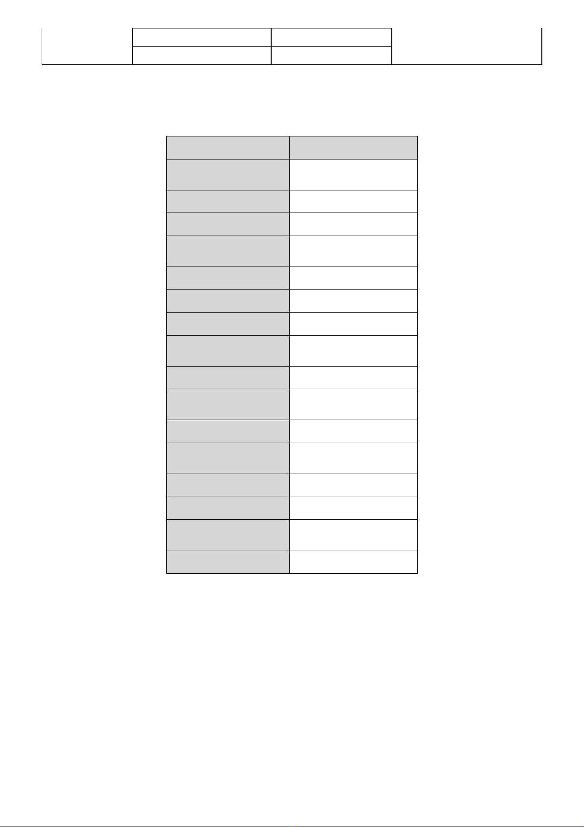
² Pay attention to the label and symbol of the instrument.
² Make sure the instrument and accessories are in good condition before use.
² Before starting up, press the trigger once or twice to make sure the jaws are well closed.
² Do not measure in flammable places, sparks may cause an explosion.
² When starting up, do not press the trigger or clamp any wires.
² Power on, the “OL” symbol is displayed during the clamp method measurement, then
measured object can be clamped.
² Do not place or store the meter for a long time in a place with high temperature, humidity,
condensation, or under direct sunlight.
² Must turned off the meter When replacing the battery.
² When the low battery low voltage symbol " " display, the battery should be replaced in
time, otherwise it will cause errors.
² The contact surface of the jaws must be kept clean and cannot be wiped with corrosive agents
and rough objects.
² When opening the trigger, avoid impact on the clamp meter, especially the jaw joint surface.
² The clamp will make a slight noise when measuring resistance. This is normal.Note the "beep-
beep-beep-" sound to distinguish the alarm.
² Pay attention to the measurement range and use environment specified of this instrument.
² The measurement lead current should not exceed the upper limit of the clamp meter.
² Use, dis assembly, calibration and maintenance of this instrument must be operated by
authorized personnel.
² Due to the reasons of this instrument, if it is dangerous to continue using it, it should be
stopped immediately, sealed up immediately, and handled by an authorized organization.
² The " " safety warning signs in the instrument and manual must be strictly followed by
the user Allow safe operation.
II
.
Introduction
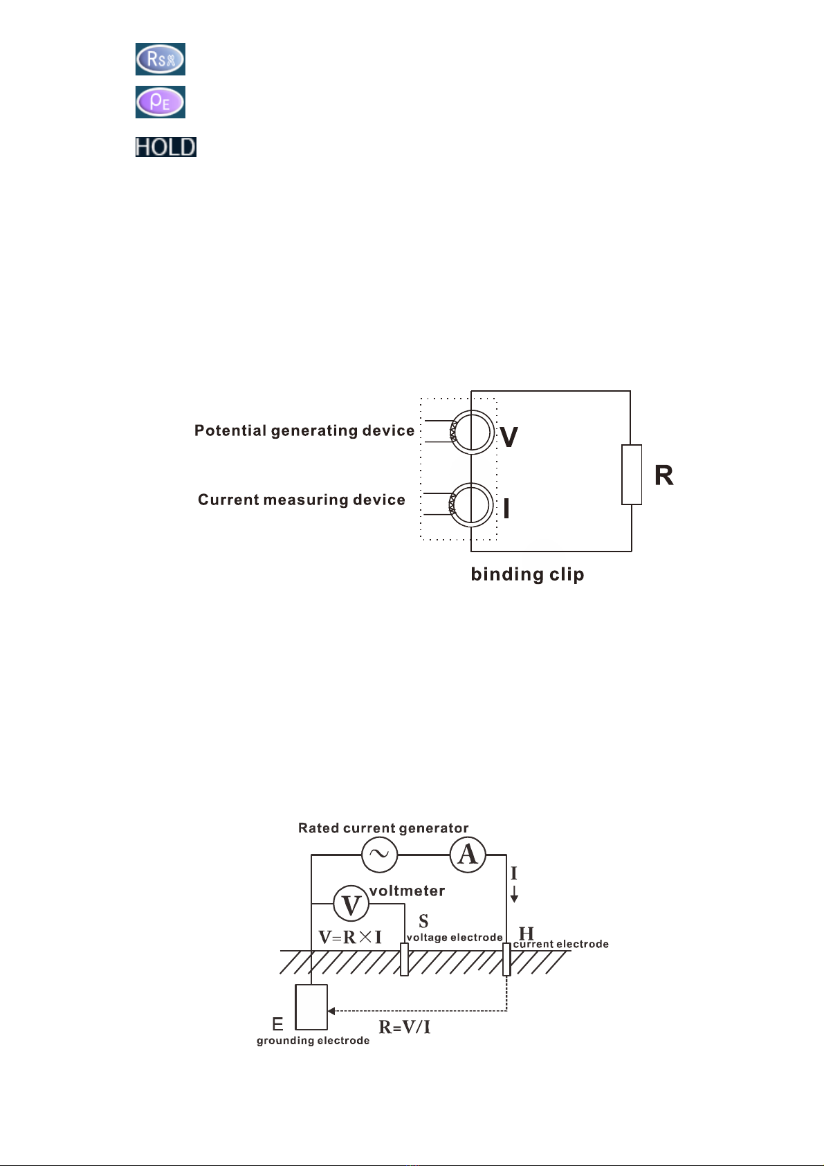
Ground pile clamp earth resistance tester also name Loop resistance tester,used for
grounding resistance test.
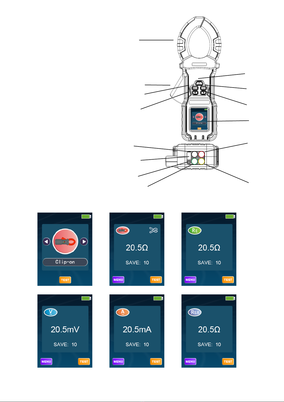
This instrument uses 2.4-inch color screen design, with clamp resistance, three or four wire
resistance, AC voltage, current measurement functions, and also has data storage, data
access, alarm, automatic shutdown and other functions.
This meter is beautiful and high-grade, wide range, high resolution, convenient operation,
easy to carry, accurate, reliable, stable performance, strong anti-interference ability.It also has a

- 3 -
shock-proof, dust-proof, and moisture-proof structure. It is a commonly used and indispensable
instrument for telecommunications, electric power, meteorology, computer rooms, oil fields,
electronic mechanical installation and maintenance, and industrial enterprises that use
electricity as industrial power or energy. It is suitable for measuring grounding resistance of
various telecommunications, electricity, meteorology, computer rooms, oil fields, power
distribution lines, transmission lines of iron towers, gas stations, factory grounding grids,
lightning rods, etc.
The ground-pile clamp ground resistance tester is controlled by a microprocessor and can
accurately detect ground resistance. It uses fast filtering technology to minimize interference. At
the same time with data storage and data upload functions.
III. Range and accuracy
Measurement
mode
Range
Resolution
Accuracy
Clamp
method
0.02Ω-9.99Ω
0.01Ω
±2%rdg±0.1Ω
10.0Ω-99.9Ω
0.5Ω
±3%rdg±0.5Ω
100Ω-199Ω
1Ω
±5%rdg±1Ω
200Ω-299Ω
5Ω
±10%rdg±5Ω
300-699Ω
10Ω
±15%rdg±10Ω
700Ω-999Ω
20Ω
±20%rdg±20Ω
1.00KΩ-1.19KΩ
30Ω
±25%rdg±30Ω
1.20KΩ-2.00KΩ
50Ω
±35%rdg±50Ω
three or four
wire method
0.01Ω-9.99Ω
0.01Ω
±2%rdg±0.2Ω
10.0Ω-99.9Ω
0.1Ω
±2%rdg±1Ω
100Ω-999Ω
1Ω
±2% rdg±15Ω
1.00KΩ-9.99KΩ
0.01KΩ
±2% rdg±0.1KΩ
10.0KΩ-30.0KΩ
0.1KΩ
±3% rdg±0.5KΩ
AC current
0.100mA -0.999mA
0.001mA
±2.5% rdg±0.1mA
1.00mA -9.99mA
0.01mA
±2.5% rdg±0.5mA
10.0mA -99.9mA
0.1mA
±2.5% rdg±1mA
0.100A-0.999A
0.001A
±2.5% rdg±0.1A
1.00A-9.99A
0.01A
±2.5% rdg±0.5A
10.0A-60.0A
0.1A
±2.5% rdg±1A
Ground
voltage
1.00V-9.99V
0.01V
±2.5% rdg±0.1V
10.0V-99.9V
0.1V
±2.5% rdg±1V
100V-600V
1V
±2.5% rdg±5V
Selection
method
0.30Ω-9.99Ω
0.01Ω
±2% rdg±0.3Ω
10.0Ω-99.9Ω
0.1Ω
±2% rdg±1Ω
100Ω-999Ω
1Ω
±2.5% rdg±15Ω
1.00KΩ-3.00KΩ
0.01KΩ
±3% rdg±0.1KΩ
Soil
resistivity
(
ρ
)
0.00Ωm~99.99Ωm
0.01Ωm
ρ=2πaR
(note1)
100.0Ωm~999.9Ωm
0.1Ωm
1000Ωm~9999Ωm
1Ωm
10.00kΩm~99.99kΩm
10Ωm

- 4 -
100.0kΩm~999.9kΩm
100Ωm
1000kΩm~9999kΩm
1kΩm
Note 1: R depends on the measurement accuracy of the three-four-wire method, π=3.14, a: 1
m~100m;
IV
.
Model of Series
Model
CE-8201
Clamp resistance
Range
0.00Ω-1800Ω
Leakage current range
0.000mA-50A
Current resolution
1uA
Three-four-wire
method range
0.00Ω-30kΩ
Soil resistivity range
0.00Ω-9999kΩm
Ground voltage range
600V
Bluetooth
○
Built-in rechargeable
battery
●
TFT Color display
●
USB Data upload
function
●
data storage
●
Real-time battery
power indicator
●
Backlight
●
Alarm function
●
Low battery voltage
indication
●
Overload protection
●

- 5 -
V
.
Technical Specification
Function
Ground resistance test, loop resistance test, AC current test, AC voltage test
Accuracy guaranteed
temperature and
humidity
23℃±5℃, below 75%rh
Power Supply
DC 3.7 Vlithium battery
Resistance resolution
0.01Ω
Current resolution
0.001mA
Voltage resolution
0.01V
Clamp Size
68mm
Display
2.4 inch color LCD screen
LCD Size
46mm×29mm
Meter Dimension
273mm×106mm×53mm
measure time
1 time/sec
USB
With USB interface,uploaded the data to the computer, saved and printed
Communication line
USB communication line 1
Data storage
Maximum 500 groups of data, display "FULL" symbol to indicate that the storage
is full
Overflow display
“OL” symbol indication when over-range overflow
Alarm function
When the measured value exceeds the alarm set value, an alarm will be issued
battery voltage
Real-time display of battery power, reminding to charge in time when battery
voltage is low
Automatic shut-down
Turn off automatically after 15 minutes
Power consumption
750mA MAX
Quality
Meter: 975g (including battery)
Working temperature
and humidity
-10℃!50℃; Below 80%rh
Storage Temperature
and Humidity
-10℃!60℃; below 70%rh
Insulation Resistance
20Ω or more (500V between circuit and outside)
Pressure Resistance
AC 3700V/rms(between circuit and outside)
External magnetic field
<40A/m
External electric field
<1V/m
Suitable for Safety
Regulations
IEC61010-1(CAT Ⅲ 300V"CAT IV 600V"Pollution Degree 2);
IEC61010-031#IEC61557-1(Ground resistance)

- 6 -
!"#
VI
.
Structure
1. Clamp
2. Jaw opening and closing trigger
3. MENU key
4. ▲
5. Power button
6. TEST
7. ▼
8. Screen
9. E port
10. H port
11. USB interface
12. Charging indicator
13. ES port
14. S port
VII
.
Interface display
7.1 Interface
(1)Main interface (2)Pincer (3)Three/four line
(4)Voltage measurement (5)Current measurement (6)Selection method
!#
"#
$#
%#
&#
'#
(#
)#
*#
!!#
!+#
!%#
!$#

- 7 -
(7)Soil resistivity measurement (8)Data query interface (9)Alarm function interface
(10)Brightness setting interface
7.2 Interface icon symbol description
⑴ . Jaw opening symbol, which is displayed when the jaw is opened. At this time, the
trigger may be pressed artificially; or the jaws have been seriously contaminated, and
the measurement cannot be continued.
⑵ . Battery voltage low symbol, when the battery voltage is too low, this symbol is
displayed. At this time, the accuracy of the measurement cannot be guaranteed, and the
battery should be replaced.
⑶ . The "OL" symbol indicates that the measured value exceeds the measuring range of
the clamp meter.
⑷ . Alarm symbol. This symbol indicates that the alarm has been turned on. When
the measured value is greater than or less than the set alarm threshold, the meter will
emit an intermittent "beep--beep--beep--" sound.
⑸ . Indicates that the clamp method is used to measure the resistance interface.
⑹ . Indicates that the resistance interface is measured by the three-four-wire
method.
⑺ . Indicates the ground voltage measurement interface.
⑻ . Indicates the AC current measurement interface.

- 8 -
⑼ . Representation selection method measurement interface.
⑽ . Indicates the soil resistivity measurement interface.
⑾ . Indicates that the current data is held and saved
VIII. Measuring Principle
8.1 Principle of Clamp Method Resistance Measurement
The basic principle of the clamp ground resistance meter to measure the ground resistance
is to measure the loop resistance.See below. The jaw part of the clamp meter is composed of a
voltage coil and a current coil.The voltage coil provides an excitation signal and induces a
potential V on the circuit under test.Under the action of the potential V, a current I will be generated
in the circuit under test.The clamp meter measures I and calculates the measured resistance R.
8.2 Three-four-wire method measurement principle
The three-wire four-wire method measures grounding resistance, which is suitable for
accurately measuring single-point grounding systems.That is, the AC rated current I flows
between the measuring object E ground electrode and the H current electrode, the potential
difference V between the E ground electrode and the S voltage electrode is calculated, and the
ground resistance value R is calculated according to the formula R=V/I.In order to ensure the
accuracy of the test, the 4-wire method is adopted and the ES auxiliary ground electrode is added.
In the actual test, ES and E are clamped on the same point of the grounding body.
8.3 Selection method measurement principle
The selection method is used to measure the grounding resistance value, which is suitable

- 9 -
for measuring the grounding resistance value of one of the parallel grounding systems without
tripping.An alternating current I is applied between the ground electrode of Re1 Re2 Re3 and the
current electrode of H, the current I3 flowing through Re3 is measured by the current clamp A,
and the potential difference V between the ground electrode of Re3 and the voltage electrode of
S is measured at the same time, and according to the formula Re3= V/I3 calculates the grounding
resistance value Re3.In order to ensure the accuracy of the test, the 4-wire method is adopted
and the ES auxiliary ground electrode is added. In the actual test, ES and E are clamped on the
same point of the grounding body.
8.4 Principle of Soil Resistivity Measurement
The soil resistivity (ρ) is measured by the 4-pole method (Winner method):The alternating
current I flows between the E ground electrode and the H current electrode, find the potential
difference V between the S voltage electrode and the ES auxiliary ground electrode,The potential
difference V is divided by the alternating current I to get the resistance value R at the middle two
points, the electrode spacing distance is a(m), according to the formula ρ=2πaR(Ωm) to get the
value of soil resistivity, the distance between HS and S-ES When equal (both are a), it is Winner's
method.For the convenience of calculation, please make the electrode spacing a far greater than
the buried depth h. Generally, a>20h should be satisfied, as shown in the figure below.
8.5 Working error principle
Among the above methods, the working error (B) is the error obtained within the rated working
conditions, which is calculated from the inherent error (A) and variable error (Ei) of the instrument.
A: Inherent error
E2:Changes caused by changes in power supply voltage
E3: Changes caused by temperature changes

- 10 -
E4: Changes caused by interference voltage changes
E5: Change in resistance of contact electrode
8.6 AC current measurement principle
True RMS measurement
8.7 Ground voltage measurement principle
Average measurement.
IX. Operation Method
9.1 Boot up
Before starting up, press the trigger once or twice to make sure the
jaws are well closed
Do not apply external force to the jaws, otherwise the accuracy of the
measurement cannot be guaranteed
Press the power button to switch the machine. It will automatically shut down after 15 minutes
after it is turned on. Pressing any key will extend another 15 minutes.
9.2 Function selection
After the meter is turned on, it automatically enters the main menu interface, you can short
press the ▲ or ▼ key to switch to the corresponding function, then short press the TEST key to
enter the menu selection item, short press the MENU key to return to the main menu interface.
9.3 Clamp measurement
1) In the menu selection, select the "clamp method" function and press the TEST key to
enter.
2) Check whether the meter displays "OL", then resistance measurement can be performed.
Otherwise, you need to check whether the clamp head is tight.
3) Open the clamp head and clamp into the resistance circuit (make sure the clamp head is
closed to ensure accuracy, otherwise you need to check whether the clamp head is
closed.). Wait for the value to stabilize and read the displayed resistance value.
4) Short press the TEST key to keep the data and save it, the screen displays the "HOLD"
icon, short press the TEST key again to cancel the hold state, the screen does not display
the "HOLD" icon.
5) Short press the MENU button to return to the main menu.
9.4 Three-four-wire method measurement
1) In the menu selection, select the "three-four-line" function and press the TEST key to
enter.
2) Insert the test wire into the bottom port of the meter according to the color, as shown in
the figure below. Wait for the value to stabilize, read the displayed resistance value
3) Short press the TEST key to keep the data and save it, the screen displays the "HOLD"
icon, short press the TEST key again to cancel the hold state, the screen does not display
the "HOLD" icon.
4) Press the MENU key to return to the main menu.

- 11 -
9.5 Ground voltage measurement
1) In the menu selection, select the "voltage measurement" function and press the TEST to
enter.
2) Insert the test wire into the S and ES ports at the bottom of the meter, as shown in the
figure below. Wait for the value to stabilize and read the displayed voltage value.
3) Press the TEST key to keep the data and save it, the screen displays the "HOLD" icon,
short press the TEST key again to cancel the hold state, the screen does not display the
"HOLD" icon.
4) Press the MENU key to return to the main menu.
9.6 AC current measurement
1) In the menu selection, select the "current measurement" function, press the TEST key to
enter.
2) Open the clamp head and clamp the wire under test. Wait for the value to stabilize and
read the displayed current value.
3) Short press the TEST key to keep the data and save it, the screen displays the "HOLD"
icon, short press the TEST key again to cancel the hold state, the screen does not display
the "HOLD" icon.
4) Press the MENU key to return to the main menu.
9.7 Selection method
1) In the menu selection, select the "selection method" function and press the
TESTkey to enter.
2) Insert the test wire into the bottom port of the meter according to the color, as shown
in the figure below. Then open the clamp head and clamp into the resistance circuit. Wait
for the value to stabilize and read the displayed current value.
Fig. 8.4-2 Schematic diagram of four-wire measurement wiring
Fig. 8.4-2 Schematic diagram of three-wire measurement wiring

- 12 -
3) Press the TEST key to keep the data and save it, the screen displays the "HOLD"
icon, short press the TEST key again to cancel the hold state, the screen does not display
the "HOLD" icon.
4) Press the MENU key to return to the main menu.
9.8 Soil resistivity measurement
1) In the menu selection, select the "Soil resistivity measurement" function and press
the TEST to enter.
2) After entering the soil resistivity test interface, the upper right corner of the LCD displays
the current depth value. The depth value can be modified by short pressing the ▲ key to
decrease 1 or short pressing the ▼ key to increase 1 step. Or long press ▲ key to
decrease 10 or long press ▼ key to increase 10 steps to modify the depth value. The
depth value range can only be 1m~100m.
3) Insert the test wire into the bottom port of the meter according to the color, as shown
in the figure below. Wait for the value to stabilize and read the displayed resistance value.
4) Press the TEST key to keep the data and save it, the screen displays the "HOLD" icon,
short press the TEST key again to cancel the hold state, the screen does not display the
"HOLD" icon.
5)Press the MENU key to return to the main menu.
9.8 Data query and deletion
1) In the menu selection, select the "Data query" function and press the TEST to enter.
2) The stored data can be viewed in steps by pressing the ▲ key to subtract 1 or short
pressing the ▼ key to increase 1 step.
3) Or by long pressing the ▲ key to decrease 10 or long pressing the ▼ key to increase 10
steps to view the stored data.
4) Press the TEST key to enter the delete mode, then press the ▲ key to confirm the deletion
of the data, or press the ▼ key to cancel the deletion of the data.
5) Press the MENU key to return to the main menu.

- 13 -
9.9 Alarm Settings
1) In the menu selection, select the "alarm function" function, press the TEST key to enter
2) The alarm thresholds for four measurement functions can be set.
3) After entering the alarm function interface, you can switch the set alarm type by short
pressing the ▲ key or the ▼ key.
4) After confirming the alarm type, short press the TEST key to enter the alarm state
selection, and then short press the ▲ key or the ▼ key to switch between setting greater
than alarm (>) or less than alarm (<).
5) After confirming the alarm status, you can short press the TEST key to enter the alarm
threshold modification status, short press the ▲ key to decrease the step or short press
the ▼ key to increase the step to modify the threshold.
6) Long press the ▲ key to move the threshold step cursor to the right, and long press the
▼ key to move the threshold step cursor to the left.
7) Short press the TEST key again to save the current settings and exit.
8) Or short press the MENU key to return to the previous layer, short press the MENU key
in the layer where the alarm type is selected to return to the menu interface.
9) Long press the MENU button on any interface to enable or disable the alarm function.
10)
X. Battery Instructions
1) When the battery voltage is too low, the battery symbol " " is displayed, please
charge it in time.
2) Low battery voltage affects measurement accuracy
3) When the boot screen flashes, the screen goes black. It may be that the battery power is
not enough to boot. Please charge it fully before starting measurement.
4) The battery symbol " " flashes to indicate that it is about to be shut down, and the
test cannot be performed at this time. Please fully charge the battery and start the test
again.
XI. Mobile APP Instructions
1) After installing the APP of "Ground pile clamp earth resistance tester. apk" in the CD, open
the APP to search for a Bluetooth device named "CLAMP_METER" (This function can
only be used for devices with Bluetooth), click it and wait for successful connection
(Bluetooth PIN code: 123456 is required for the first connection).
2) If the mobile phone is connected to the instrument through Bluetooth, the software on the
Alarm type
Alarm State
Alarm threshold
Threshold step cursor

- 14 -
computer side will not be connected. If you need to use the software on the computer
side, please disconnect the Bluetooth connection on the mobile phone before using it.
3) After successful connection, it can operate test and display online, browse history storage
data, and set alarm value.
XII. Field Application
1
!
Multi-point grounding system
For multi-point grounding systems (such as power transmission system tower grounding,
communication cable grounding systems, certain buildings, etc.), they are connected by
overhead ground wires (the shielding layer of communication cables) to form a grounding
system. See below. When measuring with a clamp meter, its equivalent circuit is as follows:
R1 is the predicted grounding resistance.
R0 is the equivalent resistance of the grounding resistance of all other towers in parallel.
Although, from the strict grounding theory, due to the existence of the so-called "mutual
resistance", R0 is not a parallel value in the usual electronic technical sense (it will be slightly
larger than the parallel value in the electronic technical sense), but, Since the grounding
hemisphere of each tower is much smaller than the distance between the towers, and after all,
the number of grounding points is large, R0 is much smaller than R1. Therefore, it is reasonable
to assume R0=0 from an engineering perspective. In this way, the resistance we measured
should be R1.
Several comparative experiments with traditional methods under different environments and
different occasions prove that the above assumptions are completely reasonable.
2
!
Limited point grounding system
This situation is also more common. For example, some poles and towers are connected to
each other by overhead ground wires; for example, the grounding of some buildings is not an
independent grounding network, but several grounding bodies are connected to each other
through wires.
In this case, if R0 in the above figure is regarded as 0, it will bring a large error to the
measurement result.
For the same reason as above, we ignore the influence of mutual resistance, and calculate
the equivalent resistance after the parallel connection of the grounding resistance in the usual
sense. In this way, for a grounding system with N (N is small, but greater than 2) grounding
bodies, N equations can be listed:
T
N
R
RRR
R2
31
21
......
11
1=
+++
+

- 15 -
R1, R2,...RN are the grounding resistances of N grounding bodies we require.
R1T, R2T,...RNT are the resistances measured on each grounding branch with clamp meter.
This is a nonlinear equation system with N unknowns and N equations. It has a definite solution,
but it is very difficult to solve it manually, even impossible when N is large. To this end, please
purchase our company’s limited point grounding system solution program software, and users
can use office computers or laptop computers for machine solution. In principle, in addition to
ignoring the mutual resistance, this method does not have the measurement error caused by
ignoring R0. However, the user needs to pay attention to: In your grounding system, if there are
several grounding bodies connected to each other, you must measure the same number of test
values for the program to solve, not more or less. The program also outputs the same number of
ground resistance values
2
!
Single point grounding system
From the principle of testing, the clamp meter can only measure loop resistance, but cannot
measure single-point grounding. However, users can use a test wire and a ground electrode near
the grounding system to artificially create a loop for testing. The following introduces two methods
for measuring single-point grounding with a clamp meter. This method can be applied to
occasions where the traditional voltage-current method cannot be tested.
⑴!
Two-point method
As shown in the figure below, find an independent grounding body RB with good grounding
near the tested grounding body RA (such as nearby water pipes, buildings, etc.). Connect RA and
RB with a test wire.
Because the resistance measured by the clamp meter is the series value of two grounding
resistances and the resistance of the test line.
RT=RA+RB+RL
RT is the resistance measured by the clamp meter.
RL is the resistance of the test line
Therefore, if the measured value of the clamp meter is less than the allowable value of
grounding resistance, then the grounding resistance of the two grounding bodies is qualified.
⑵!
Three-point method
As shown in the figure below, find two independent grounding bodies RB and RC near the
tested grounding body RA.
The first step is to connect RA and RB with a test line, as shown in the figure below. Use the
clamp meter to read the first data R1.
NT
N
NR
RRR
R=
+++
+
-)1(21
1
......
11
1

- 16 -
The second step is to connect RB and RC, as shown in the figure below. Use the clamp
meter to read the second data R2.
The third step is to connect RC and RA, as shown in the figure below. Use the clamp meter
to read the third data R3.
In the above three steps, the readings measured in each step are the series value of two
grounding resistances. In this way, you can easily calculate each ground resistance value:
because of: R1=RA+RB R2=RB+RC R3=RC+RA
So: RA=(R1+R3-R2)÷2
This is the ground resistance value of the grounding body RA. In order to facilitate the
memorization of the above formula, the three grounding bodies can be regarded as a triangle,
and the measured resistance is equal to the adjacent side resistance plus the opposite side
resistance divided by 2.
The ground resistance values of the other two grounding bodies as reference objects:
RB=R1-RA RC=R3-RA

- 17 -
XIII
.
Accessories
Meter
1 pcs
Test line
4 pcs
Simple test line
2 pcs
USB communication line
1 pcs
Monitoring software CD
1 pcs
Instructions, warranty
1 set
Instrument box
1 pcs

- 18 -
The content of this user manual cannot be used as a reason for using the product for special
purposes.
The company is not responsible for other losses caused by use.
The company reserves the right to modify the contents of the user manual. If there are changes,
no further notice will be given.
Table of contents
Other HTC Test Equipment manuals