2
Connecting Your KVM Extender
Preparing Your Site
Before you can install the product, you need to prepare your site.
1.Determine where the host computer will be located and set up the computer.
2.Determine where the console devices (mouse, keyboard, monitor) will be located and place them
appropriately.
3.a) If you are using surface cabling, ensure you have enough Category 5 unshielded twisted pair (UTP)
network cabling to connect the Local unit to the Remote unit’s location, and that each end is terminated with
a RJ45 connector. The cabling should not go through any networking equipment (i.e. router, switch).
OR
b) If you are using premises cabling, ensure that the Category 5 unshielded twisted pair (UTP) network
cabling between the Local unit and the Remote unit has been properly terminated in a wall outlet in each
location and there is a patch cable long enough to connect the Remote Unit and the Local unit to their
respective outlets. The cabling should not go through any networking equipment (i.e. router, switch).
CAUTION: The UTP network cables that connect the Local and Remote Units
carry electrical current and should not be plugged in to other devices, as they
may cause damage. We strongly recommend marking the cables you are
using with this product at both locations for easy identification.
Local Unit Installation
1.Switch off the computer and disconnect any unnecessary devices/peripherals.
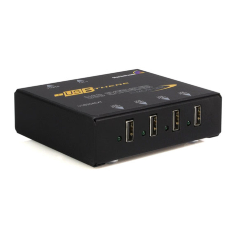
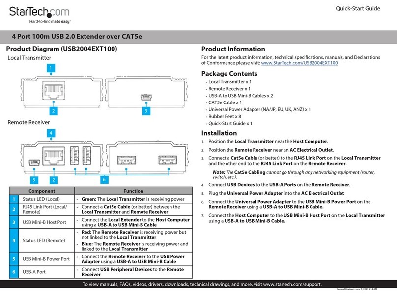
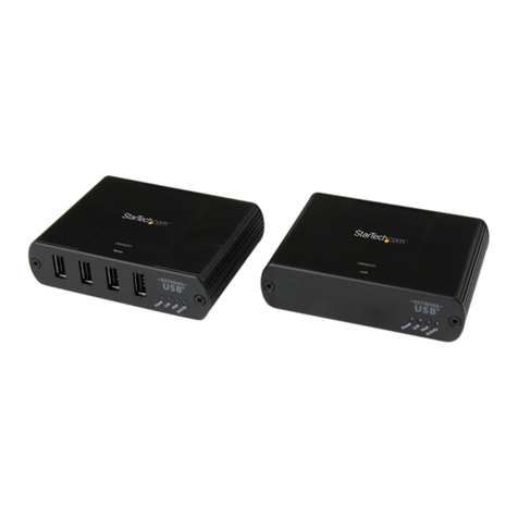
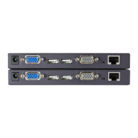
2.Using the provided cables, connect the USB cable from the USB type B connector on the Local unit to
an available USB port on the computer system. Connect the DVI-D cable from the Local unit to the DVI
connector on the computer system.
NOTE: If using audio, no separate cables are required, as it will be carried over USB.
3.Connect the UTP cable connection for the Remote unit to the RJ45 connector on the Local unit. If using
premises cabling, connect the opposite end of the patch cable to the terminated wall outlet.
Installing the Remote Unit
1.Place the Remote Unit near the remote station.
2.Using a DVI-D cable (not included) connect a monitor to the DVI-D connector on the Remote unit.
3.Connect a USB keyboard and/or mouse to any of the USB Hub ports on the Remote unit.
4. OPTIONAL: Connect any additional USB peripherals you wish to use to the Remote unit. An external USB
hub (powered) may be connected to the Remote unit, if additional USB ports are required.
5.Connect the UTP cable connection from the Local unit to the RJ45 connector on the Remote unit. If using
premises cabling, connect the opposite end of the patch cable to the terminated wall outlet.
6.Connect the power adapters to the Local and Remote units. Each unit uses a specific power adapter (5VDC
for Local, 24VDC for Remote), so ensure the correct power adapter is connected, otherwise damage may
occur.
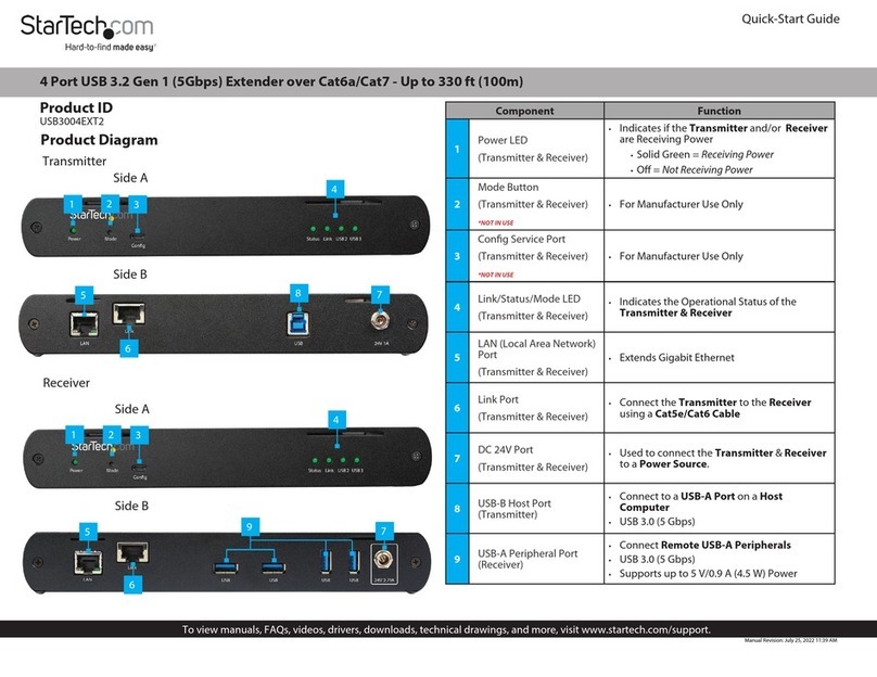
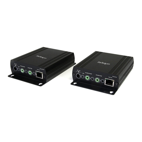
7.The “Status” LED should light up on both units to indicate power. The “Link” LED should also light up to
indicate a connection between the Local and Remote units is established.
