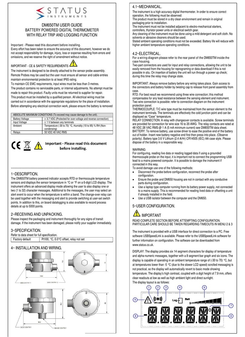
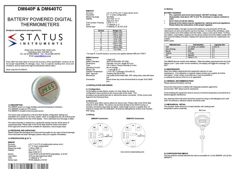
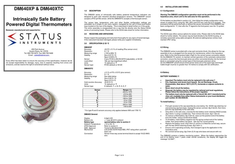
Status Instruments DM650XTM User manual

D2629-01-04 CN5795 User guide
DM650XTM USER GUIDE
ATEX APPROVED BATTERY POWERED DIGITAL
THERMOMETER
Important - Please read this document before installing; in particular the
ATEX information when applicable to the application.
Every effort has been taken to ensure the accuracy of this document; however, we
do not accept responsibility for damage, injury, loss or expense resulting from errors
and omissions, and we reserve the right of amendment without notice.
IMPORTANT - CE & SAFETY REQUIREMENTS
The instrument is designed to be battery powered. The user must ensure all sensor
and cable entries maintain environmental protection to at least IP65 rating.
The product contains no serviceable parts, or internal adjustments. No attempt must
be made to repair this product. Faulty units must be returned to supplier for repair.
This product must be installed by a qualified person. All electrical wiring must be
carried out in accordance with the appropriate regulations for the place of
installation.
ABSOLUTE MAXIMUM CONDITIONS (To exceed may cause damage to the unit).
Ambient temperature depending on batteries
1.5 v lithium (ENERGIZER L92)
Temperature (-20 to 60) °C
---------------------------------------------------------------------------------
1~DESCRIPTION.
The DM650XTM accepts RTD or thermocouple temperature sensors, and displays
the sensor temperature in °C, °F, °R or K on a 6-digit LCD display. In addition to
this, on board datalogging is also available to record process details at up to 1500
points.
2~RECEIVING AND UNPACKING.
Please inspect the packaging and instrument thoroughly for any signs of transit
damage. If the instrument has been damaged, please notify your supplier
immediately.
3~SPECIFICATION.
Refer to data sheet for full specification. Download at www.status.co.uk
Factory default
Eu Pt100, Unit °C, DP 0.0, Offset = 0.0, Pass-code =0000
10 s update, Logging = off
4~SPECIAL CONDITIONS for use to comply with CE and
safety
1
The equipment must be installed correctly, providing
environmental protection of IP 65 or greater. Steps must
be taken to ensure the maximum ambient operating range
is not exceeded, in particular, the temperature probe
surface temperature at the point of entry into the
equipment housing.
2
The maximum recommended sensor wire length is 10
metres. To maintain full CE EMC requirements for
industrial applications, max length is 3 metres.
3
Apart from battery replacement, the device contains no
serviceable parts. No attempt must be made to repair this
product. Please return faulty devices to the supplier.
4
This equipment must be installed by a qualified person. All
electrical wiring must be carried out in accordance with the
appropriate regulations for the place of installation.
5
Primary Cell Batteries –fire, explosion and severe burn
hazard. Do not attempt to re-charge, crush, incinerate,
disassemble, heat above 50 °C or expose to water.
Disposal of the batteries must conform to the regulations
applicable to the area of use.
ATEX Applications. Special Conditions for Safe Use.
6
Only suitable for connection to Thermocouple or RTD
temperature sensors.
The sensor will conform to the requirements for
simple apparatus as defined in IEC 60079-11 clause
5.7.
7
As the display is physically connected to a possible
source of heating or cooling (the temperature sensor),
the temperature at the point of connection shall be
within the ambient temperature range as given in the
certificate.
8
Sensor connection using multi-strand wires must use
a crimp to avoid the possibility of a strand of wire
becoming free.
9
Batteries (two) –use only type L92 manufacturer
Energizer (ultimate Lithium) size AAA, 1.5 V.
Temperature range -40 to 60 deg C
Approval Baseefa14ATEX0107U.
Available worldwide.
10
Batteries to be replaced in safe area only.
11
Electrostatic hazard –do not charge by rubbing or
cleaning with a solvent.
12
The unit shall be cleaned regularly to prevent the
build-up of excessive dust layers. Avoid rubbing.
5~ ATEX INSTRUCTIONS.
User instruction for DM650XTM electrical apparatus when
used in a hazardous area.
Important: Read and understand this section before any
installation.
Refer to Eu Type Examination Certificate
CML 20ATEX2030X
See Specific Conditions of Use (Special Conditions)
Product Information
Zone Area
Classification
Gases
Dusts
Zone 0
Zone 20
Working Parameters
Terminals 1,2,3,4
Uo = 3.66 V dc, Io = 17.0 mA, Po = 0.016 W

D2629-01-04 CN5795 User guide
6~INSTALLATION
Figure 1: Back panel battery cover fitted
Figure 2: Back panel battery cover removed
6~1 Battery
ATEX applications use only Energizer L92 batteries, 2
required. Do not use any other type, or mix batteries with any
other type. Batteries must be replaced in the safe area. Follow
the procedure below. When the cap assembly is removed and
disconnected, transport cap assembly to the non-hazardous
area. When the batteries are replaced, be sure the battery
cover is fitted before returning to the hazardous area. Failure
to perform the battery replacement correctly may result in an
unsafe system.
Please observe the above battery warnings. Refer to Figure 2
(Observe polarity). Battery type 1.5 V Lithium ENERGIZER L92
AAA size offering longer life at high temperature: must be used for
ATEX applications.
To fit or replace batteries, use the following procedure:
Note: If fitted, the battery isolation tab will need to be removed
before use.
1
Turn the cap retaining ring anti-clockwise until the ring
releases from the enclosure body.
2
Remove the cap assembly from the enclosure base, un-
plug the 4-way connector. The cap assembly should
now be totally free from the base.
3
For ATEX applications: at this stage, if not already
in a safe area, the cap must be transported to a safe
area.
4
Remove the battery cover by unscrewing the two
retaining screws. If fitted, remove the batteries to be
replaced.
5
Fit new batteries. Observe the polarity symbols marked
on the battery holder.
6
Replace the battery cover, ensure the information label
is visible. Secure the two retaining screws.
7
For Atex applications, return the cap assembly to
the hazardous area.
8
Inspect the cap O ring seal for correct alignment.
Reconnect the 4-way plug and site the cap assembly
back on the case base.
9
Tighten the retaining ring until it stops turning smoothly.
At this point, tighten an additional 1/12 of a turn.
Use the indents on the retaining ring to gauge 1/12 of a
turn as 12 indents are equally spaced around the
retaining ring.
Please dispose of batteries in a responsible way
6~2 Maintenance
The following maintenance is required.:
Battery replacement: the expected battery life in normal
operation well exceeds 1 year; the exact life depends on many
factors such as the number of log reads, response time and the
ambient operating temperature. A low-battery warning is
displayed when the batteries’voltage approaches discharge. It
is recommended at this time the batteries are replaced within a
month.
If required, the device may be cleaned with a damp cloth. For
ATEX applications please refer to “ATEX Applications Special
Conditions for Safe Use” for further information on cleaning.
The device uses advanced circuitry and high stability
components to maintain accuracy. For recalibration, the device
must be returned to the supplier for factory calibration. A single
point offset trim is provided to cancel any sensor error if
required.
The device contains no other user-serviceable parts. Please
return faulty units to your supplier for factory repair or
replacement.
6~3 Sensor wiring
Figure 3: Connection diagram
Important –unplug the 4-way sensor connector from the
device during wiring, re-connect when wiring is complete.
Ensure the sensor wires are long enough (80 to 100 mm) to
allow easy access for reconnecting the plug to the device and,
if required, access to the configuration switch.

D2629-01-04 CN5795 User guide
6~3 Sensor wiring (continued)
General –the instrument is designed to be directly attached to the
sensor probe assembly. Remote Probes may be used but the user
must ensure all sensor entries maintain environmental protection to
at least IP65 rating. To comply with CE EMC requirements the
sensor wires should be no longer than 3 metres. When using an
RTD, for best results we recommend using three-wire connection;
this method compensates for any lead resistance between the
sensing element and instrument. Two-wire RTD connection is
possible by linking pins 1 and 3: refer to Figure 3.
Thermocouple wire type must be maintained from the sensor
element to the instrument terminals. The terminals are effectively
the cold junction point and can be displayed as “Tamb” ambient
temperature.
7~USER CONFIGURATION.
IMPORTANT
READ COMPLETE SECTION BEFORE ATTEMPTING
CONFIGURATION
The device is configured using a single push button and a series of
menus displayed on the LCD screen. The push button is internally
located and is intended for configuration and commissioning
operations only. The device may be supplied pre-configured if
requested at the time of purchase. Refer to the configuration
section for further details.
7~1 Display information
Figure 4: Display layout
1 NFC icon active when NFC field is detected.
2 Comms icon active during communication.
3 Log bar. The log bar will show the percentage of logs taken up to
the maximum.
4 Warning Symbol
7~2 Push-button Configuration
A single push-button is provided together with
a simple configuration menu for configuration.
The following variables can be configured:
sensor type, temperature unit, decimal place
and offset.
Single press, in display mode to enter the menu lists.
The configuration settings are presented as a series of menu lists.
A single press (click) from display mode is used to enter the
configuration menu lists.
The order of the menu lists options is as follows:
•Sensor type.
•Display unit.
•Decimal place.
•Response time.
•Offset.
•Pass code.
Long Press > 2 seconds, in configuration mode
To advance through the menu option lists, press continuously for
over 2 seconds. This action is used to advance to the next option
in the menu list and to confirm a selection, and when a variable
has been selected.
Single press and Double press, in configuration mode
A single press (click) from configuration mode. This action steps
through the selected menu list variable, e.g. sensor menu list
variable = Pt100 Eu, single press will select Pt100 US. A double
press steps through the list in reverse order.
No press > 12 seconds, in configuration mode
To escape from the configuration menu, allow a period of 12
seconds with no button action.
Alternatively, stepping through the menu list options will return the
device to the run mode.
SENSO R CON FIGURAT ION
Pt100 Eu, Pt100 US
Ni120, Ni100
Cu100, Cu53
Thermocoupl e type
K, J, E, N, T, R, S, L, B
T AMB (amb ient case
temperature)
DISPLAY MODE
UN ITS CO NFIGU RATION
°C
°F
Kelvin
Single
Press
Doubl e
Press
Double
Press
DP CONFIGURAT ION
0.0
0.00
Double
Press
Doubl e
Press
Single
Press SET OFFSET
Range
(-10.0 to 10.0)
Set Up
Add 0.1
Set Down
Subtract 0.1
DISPLAY MODE
To E scap e Wai t 12 s econd s
With no bu tton Action
Press
Press > 2 s
Press > 2 s
Press > 2 s
PASS C
Press > 2 s
Set each digit i n turn
Press > 2 advances to next digit
Single
Press
To Escap e Wai t 12 second s
With no bu tton Action
Press > 2 s
RESPONSE TIME
5,10,30,60 s
Press > 2 s
Double
Press
Single
Press
Single
Press
Single
Press
Figure 5: configuration menu flow diagram.

D2629-01-04 CN5795 User guide
IMPORTANT
NFC functions are only to be carried out in the safe area or with a
suitably approved ATEX NFC device.
7~3 NFCLink software configuration
The NFC interface allows the instrument to communicate with an
Android device using NFC connectivity.
The prime function of the interface is to configure the device using
the free app, which is available for downloading to Android
devices.
The app allows the user to set the parameters shown in the
configuration screen (below).
Tag No and Contact are free type fields, saved onto the device.
Latitude and Longitude can be used to add the unit’s location
which is added to the log in the NFCLogLink software.
Read process screen showing maximum and minimum values
since the last clear command.
Configuration screen
7~4 NFC Loglink configuration software
The NFC interface allows the instrument to communicate with an
Android device using NFC connectivity.
The prime function of the interface is to read logged data from the
device using the free app, which is available for downloading to
Android devices.
The app allows the user to read existing logs, change the log
manifest, start a new log, synchronise the instrument clock and
reset the maximum/minimum readings.
Logs can run to a fixed number and stop or continually roll over. Up
to 1500 log points can be recorded. The start of the log can be
delayed up to one month.
Data from NFCLogLink can be viewed on screen as a graph or
table and can also be saved to a csv file.
Note: For larger logs the data may take over a minute to fully
download via the NFC interface.
Note: Not all Android devices fully implement the near field
communication (NFC) standard and may not hold the full 1500 log
points.
Main NFCLogLink screen
Graph view in NFCLogLink
Data table view in NFCLogLink
Download Status Instruments apps from the Google Play Store.
Status Instruments Ltd, Status Business Park, Gannaway Lane, Tewkesbury,
Gloucestershire, UK, GL20 8FD
Web Page: www.status.co.uk,
Email: sales@status.co.uk
Tel: +44 (0) 1684 296818, Fax: +44 (0) 1684 293746
Other Status Instruments Thermometer manuals
Popular Thermometer manuals by other brands
CO/Tech
CO/Tech E0201ST2H2 Original instructions

Easy@Home
Easy@Home NCT-301 Faq
FLORABEST
FLORABEST FFGT 433 A1 Operating instructions and safety instructions
sauermann
sauermann KIRAY 100 user manual
Dwyer Instruments
Dwyer Instruments IR4 Series quick start guide
VOLTCRAFT
VOLTCRAFT IR 500-8S SE operating instructions
