Status RH1800 User manual

RH1800
Router
Fresatrice verticale
Оберфреза
Фрезер
IT
EN
BG
RU
Original instructions
Istruzioni originali
Оригинална инструкция за използване
Оригинальная инструкция по эксплуатации

2
RH1800
2
1
4
7
9
8
5
6
3
A
a1
3 mm
C
c2
c1 4
DB
d2d1 14
7
b1
10
8
EN

3
RH1800
17
11
16
12
13
14
F
17
GH
E
18 19
e1
14
f1
f2
19
5
15
e1
EN

4
INTENDED USE
GENERAL SAFETY RULES
INTENDED USE
GENERAL SAFETY RULES
EN
This device is intended to mill grooves, edges, proles and slots on a wooden, plastic or
light surface, as well as copy milling. This device is not intended for outdoor use.
WARNING! Read all safety warnings and all instructions. Failure to follow the warnings and
instructions may result in electric shock, re and/or serious injury.
Save all warnings and instructions for future reference.
The term "power tool" in the warnings refers to your mains-operated (corded) power tool or
batteryoperated (cordless) power tool.
WORK AREA
• Keep work area clean and well lit. Cluttered and dark areas invite accidents.
• Do not operate power tools in explosive atmospheres, such as in the presence of
ammable liquids, gases or dust. Power tools create sparks which may ignite the dust or
fumes.
• Keep children and bystanders away while operating a power tool. Distractions can
cause you to lose control.
ELECTRICAL SAFETY
• Power tool plugs must match the outlet. Never modify the plug in any way. Do not
use any adapter plugs with earthed (grounded) power tools. Unmodied plugs and
matching outlets will reduce risk of electric shock.
• Avoid body contact with earthed or grounded surfaces such as pipes, radiators,
ranges and refrigerators. There is an increased risk of electric shock if your body is earthed
or grounded.
• Do not expose power tools to rain or wet conditions. Water entering a power tool will
increase the risk of electric shock.
• Do not abuse the cord. Never use the cord for carrying, pulling or unplugging the
power tool. Keep cord away from heat, oil, sharp edges or moving parts. Damaged or
entangled cords increase the risk of electric shock.
• When operating a power tool outdoors, use an extension cord suitable for outdoor
use. Use of a cord suitable for outdoor use reduces the risk of electric shock.
• If operating a power tool in a damp location is unavoidable, use a residual current
device (RCD) protected supply. Use of an RCD reduces the risk of electric shock.

5
GENERAL SAFETY RULES
EN
PERSONAL SAFETY
• Stay alert, watch what you are doing and use common sense when operating a
power tool. Do not use a power tool while you are tired or under the inuence of
drugs, alcohol or medication. A moment of inattention while operating power tools may
result in serious personal injury.
• Use safety equipment. Always wear eye protection. Safety equipment such as
dust mask, non-skid safety shoes, hard hat, or hearing protection used for appropriate
conditions will reduce personal injuries.
• Avoid accidental starting. Ensure the switch is in the o position before plugging in.
Carrying power tools with your nger on the switch or plugging in power tools that have
the switch on invites accidents.
• Remove any adjusting key or wrench before turning the power tool on. A wrench or a
key left attached to a rotating part of the power tool may result in personal injury.
• Do not overreach. Keep proper footing and balance at all times. This enables better
control of the power tool in unexpected situations.
• Dress properly. Do not wear loose clothing or jewellery. Keep your hair, clothing and
gloves away from moving parts. Loose clothes, jewellery or long hair can be caught in
moving parts.
• If devices are provided for the connection of dust extraction and collection facilities,
ensure these are connected and properly used. Use of these devices can reduce dust
related hazards.
POWER TOOL USE AND CARE
• Do not force the power tool. Use the correct power tool for your application. The
correct power tool will do the job better and safer at the rate for which it was designed.
• Do not use the power tool if the switch does not turn it on and o. Any power tool
that cannot be controlled with the switch is dangerous and must be repaired.
• Disconnect the plug from the power source before making any adjustments,
changing accessories, or storing power tools. Such preventive safety measures reduce
the risk of starting the power tool accidentally.
• Store idle power tools out of the reach of children and do not allow persons
unfamiliar with the power tool or these instructions to operate the power tool.
Power tools are dangerous in the hands of untrained users.
• Maintain power tools. Check for misalignment or binding of moving parts, breakage
of parts and any other condition that may aect the power tools operation. If
damaged, have the power tool repaired before use. Many accidents are caused by
poorly maintained power tools.
• Keep cutting tools sharp and clean. Properly maintained cutting tools with sharp
cutting edges are less likely to bind and are easier to control.


6
SAFETY INSTRUCTIONS FOR ROUTERS
EN
• Use the power tool, accessories and tool bits etc. in accordance with these
instructions, taking into account the working conditions and the work to be
performed. Use of the power tool for op-erations dierent from those intended could
result in a hazardous situation.
SERVICE
• Have your power tool serviced by a qualied repair person using only identical
replacement parts. This will ensure that the safety of the power tool is maintained.
• Only hold the power tool by the insulated handle areas as the router may touch the
tool’s mains cable. Contact with a live wire could cause metal parts of the device to
become live and lead to electric shock.
• Fix and secure the work piece to a stable surface using clamps or other means. When
only securing the work piece by hand or against your body it will remain unstable,
which could lead to loss of control.
• Wear a dust mask.
• The permissible rotational speed of the router tool must be at least as high as the
maximum speed indicated on the electrical power tool. Parts used at higher than
permissible speeds may be ruined.
• The router or other parts must t precisely in the collet (shaft diameter 6/8/12) of your
electric power tool. Cutting tools which do not t precisely in the collet of the electric
power tool turn unevenly, vibrate strongly and can lead to a loss of control.
• Always switch on the electrical power tool before placing it against the workpiece.
There is also the risk of kickback if the electric power tool becomes caught in the work-
piece.
• Keep your hands away from the cutting area and the router. Keep your second hand
on the additional handle or on the engine housing. If you hold the router with both
hands, they cannot be injured by the router.
• Never use on metal objects, nails or screws. The router can become damaged and this
may lead to higher vibrations.
• Use suitable detectors in order to look for hidden supply lines, or consult your local
power authority. Contact with electric lines can lead to re and electric shocks. Damage
to a gas line can lead to explosions. Breaking a water line can cause damages.
SAFETY INSTRUCTIONS FOR ROUTERS

7EN
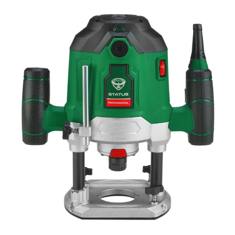
TOOLS PARTS OVERVIEW
TOOL PARTS OVERVIEW
Router – front side
1. Power cable with power plug
2. Handle
3. Rotation direction arrow
4. Guiding rod set screw
5. Ground plate
6. Ground plate groove
7. Adjustable stopper
8. Measuring stick set screw
9. Measuring stick with scale
10. Measuring stick ne adjuster
Detail graphic A
a1 Read-o point of measuring stick
Detail graphic B
b1 Metal point of measuring stick
Detail graphic C
c1 Guiding rod of parallel stopper
c2 Parallel stopper
Detail graphic D
d1 Mould cutter
d2 Collet
Router – back side
11. Rotation regulator
12. Height adjuster
13. Vacuum nozzle
14. Spindle screw
15. Extendable rod
16. Turn-on safety latch
17. On / o switch
18. Long bolt of ground plate
19. Copy slice cutter
Detail graphic E
e1 Spindle adjustor
e2 Spanner
Detail graphic F
f1 Template
f2 Copy tool
Detail graphic G
Floor view of the ground plate
Detail graphic H
Schema of the correct router direction

8
OPERATION
EN
Vacuuming
• The inside diameter of the vacuum nozzle (13) is 40 mm. Insert an appropriatesized
tube into the vacuum nozzle.
• Connect your router with the vacuum nozzle to a household vacuum cleaner or to a
dust-extracting apparatus.
• Through this, you attain an optimal vacuuming on your work piece. The advantage: you
improve your machine as well as your own health. In addition, your work space stays
cleaner and safer.
• While working, existing dust can be dangerous ( Safety advice). The vacuum cleaner
used for the vacuuming must be intended for the material being worked on.
Remember that health-hazardous materials, such as asbestos, may not be used.
• In the industrial use of the machine, special regulations apply for vacuuming
mechanisms. Check the requirements with your professional association if necessary.
Mould cutter selection
• In this router, the mould cutter can be replaced by the following mould cutters: 6 mm,
8 mm,12 mm
• Most mould cutters can be found in these sizes. You can also use mould cutters out of
the following material, among other things:
HSS: Softwoods designated for working
TCT: Hardwoods, ake board, plastic, and aluminumdesignated for working
• Choose the appropriate mould cutter for your work. The following table shows which
mould cutter can be used for which type of work.
OPERATION
1Slit cutter 6Round
cutter
2Screwc utter 7Screw
cutter
3Vs crew
cutter 8Vs crew
cutter
4
Cone/
trapeze
cutter
9Screw
cutter

9
Mould cutter adjustment
• Pull out the power plug (1) and allow the mould cutter to completely stop spinning.
• Clean the screw, collet, and shaft of the mould cutter before operation if necessary.
• Remove all packaging material completely from the mould cutter heads.
• Loosen the height adjuster (12) to adjust the router to the highest position. Next
tighten the height adjuster again.
• Turn the router upside down.
• Press the spindle adjuster (e1); you must eventually turn the spindle screw a bit, so that
the adjuster can engage. Keep it pressed.
• With a wrench, loosen the spindle screw (14) and screw this, including the collet (d2),
completely o.
• Choose the appropriate collet (d2) for the selectedmould cutter.The stemdiameter of
the mould cutter muss agree with that of the collet.
• Insert the shaft of the mould cutter (d1) into the collet (d2).
• Set the mould cutter with the collet (d2) and screw(14) in the mould cutter spindle, and
screw it with your hand.
• The mould cutter must protrude at least 3mmout of the screw!
• Press the spindle adjuster (e1) again and pull the spindle screw tight with a wrench.
• Be aware that the mould cutter depth must be re-adjusted.
Rotation speed adjustment
Warning: Turn the machine o before changing the rotation speed. Check the positioning
and rotation of the mould cutter before operating the machine!
• The appropriate rotation speed depends on the material to be work on and the
diameter of the mould cutter.
• Select the rotation speed with the switch for the rotation speed regulator. You can
select 7 dierent switch positions: From switch position„MIN“ (minimum rotation speed)
to switch position„MAX“ (maximum rotation speed). The rotation speed can be set
according to the desired speed from a level of 1 through 5. The required rotation speed
depends on the working material and the type of work. The rotation speed can best be
determined by a test run.
EN
OPERATION
3Vs crew
cutter 8Vs crew
cutter
4
Cone/
trapeze
cutter
9Screw
cutter
5Round
cutter 10 Plan/ band
cutter

10
EN
• After working with low rotation speed for a long time, allow the machine to cool down
for about 2 minutes with it running idle at maximum rotation speed.
Adjustment with an arbitrary object
You can simply cut as deep as the height of any chosen object.
• Set the adjustable depth stopper (7) so that the height measuring stick is brought
down to the lowest level.
• Loosen the set screw (8) of the depth measuring stick.
• Loosen the height adjuster (12) and press the mould cutting tool with the handle far
under, so that it touches the work piece.
• Secure this adjustment by tightening the height adjuster.
• Lift the depth measuring stick (9) up.
• Lay your selected object between the lowest level of the depth stopper (7) and the
depth measuring stick (9). The metal point (b1) of the depth measuring stick (9) must
touch the selected object.
• Secure this adjustment by tightening the set screw (8) of the depth measuring stick.
• The mould cutter depth is now set.
• Now loosen the height adjuster to get the mould cutter ready for operation.
Calibration in 3 mm intervals
The adjustable depth stopper (7) allows a quick approximate adjustment in 3 mm intervals.
• Insert the appropriate mould cutter.
• Set the adjustable depth stopper (7), so that the height measuring stick shows the
lowest level when brought down.
• Loosen the set screw (7) of the depth measuring stick.
• Loosen the height adjuster (12) and press the mould cutting tool with the handle far
under, so that it touches the work piece.
• Secure this adjustment by tightening the height adjuster.
• Lift up the depth measuring stick (9) a little.
• Now adjust the depth stopper by turning it.
• For every step that it climbs, an additional 3 mm is added to the mould cutter depth.
So when it is at position 3, the mould cutter depth is 9 mm.
• Adjust the depth measuring stick with the metal point (b1) so that it is on the desired
step, while you tighten the set screw (8) of the depth measuring stick.
Calibration calculation
You know the exact cutting depth in centimeters and would like to change it. You would
like to drill exactly a 2 mm deep screw into a wooden board, for example.
• Insert the appropriate mould cutter.
• Adjust the depth stopper (7), so that the height measuring stick shows the lowest level
when brought down.
OPERATION

11 EN
• Loosen the set screw (8) of the depth measuring stick.
• Loosen the height adjuster (12) and press the drilling tool with the handle (2) far under,
so that it touches the work piece.
• Secure this adjustment by tightening the height adjuster.
• Make sure that the depth measuring stick (9) with the metal point (b1) is sitting on the
depth stopper.
• Now the starting position can be read from the read-o point on the depth measuring
scale (a1).
• The depthmeasuring stick (9) canbenely adjusted, so that the desiredcentimeter
number is displayed on the scale. Turn the ne adjuster of the depth measuring stick
(10) in the desired direction.
• The desired drilling depth can simply be subtracted fromthe displayed centimeter
number. (Example: 4 cm is displayed on the scale, and you want to drill 2 mm. So the
scale should be adjusted to display 3.8 cm.)
• Lift the depth measuring stick up, so that the read-o point on the scale (a1) shows the
corresponding value. (3.8 cm in the example)
• Now adjust the depth measuring stick (9) with the new calibration. The depth
measuring stick can be locked in position by tightening the set screw (8). You now have
set the desired drilling depth.
• Now loosen the height adjuster (12) to get the mould cutter ready for operation.
Drilling direction
The drilling must always turn in the opposite running direction of the drill counterrotation).
The rotation direction is indicated by the arrow (3) on the front of the machine. See
illustration (H).
Turning On/O
• To operate the machine, rst press and hold the safety latch (16). Then press and hold
the big on/o switch (17). The drill is now turned on.
• As soon as you let go of the on/o switch (17), the drill will turn o. In the case that you
let go of the safety latch (16), the on/o switch (17) will be locked again.
Mould cutting
• Loosen the height adjuster (12) and set the mould cutter on the work piece.
• While operating, press the mould cutter until the height stopper (7) stops.
• Continue pressing the mould cutter and tighten the height adjuster (12) again. Now
push the mould cutter as desired by grasping both router handles.
• To turn the machine o, simply let go of both orange buttons (16, 17) on the right
handle.
• Hold the router rmly until the motor has stopped.
OPERATION

12
EN
GENERAL INSPECTION
Regularly inspect all fasteners and ensure they are properly tightened. Should any of the
screws be loose, retighten it immediately to avoid hazards.
If the replacement of the supply cord is necessary, this has to be done by the manufacturer
or his agent in order to avoid a safety hazard.
CLEANING
For safe operation always keep the machine and its ventilation slots clean.
Regularly check to see if any dust or foreign matter has entered the ventilation slots and the
grills around the switches. Use a soft brush and/or air jet to remove any accumulated dust.
MAINTENANCE
MAINTENANCE
Assembly of the parallel stopper (ill. C)
• Take the screws and washers out of the guiding rods (c1).
• Place the heads of the guiding rods in the corresponding holes of the parallel stopper
(c2).
• Mount the parallel stopper (c2) with the screws and washers onto the guiding rods (c1).
• Insert the guiding rods (c1) into the groove (6) of the ground plate (5).
• Set the desired distance between the parallel stopper and mould cutter.
• Tighten the guiding rods (c1) with the set screws (4) on the ground plate (5).
• Set the parallel stopper (c2) on the edge of the work piece.
• Now cut by taking the router parallel along the work piece. Mould cutting copies
Creating several objects of the same shape can be done with the copy slice cutter (19).
• Remove both long screws (18) from the underside of the ground plate (5).
• Now fasten the copy slice cutter (19) with the two long screws (18) on the underside of
the ground plate.
Mould cutting copies
• Creating several objects of the same shape can be done with the copy slice cutter (19).
• Remove both long screws (18) from the underside of the ground plate (5).
• Now fasten the copy slice cutter (19) with the two long screws (18) on the underside of
the ground plate.
• The protrusion in the middle of the copy slice cutter must jut out to the outside (ill. G).
• Ax two work pieces to your workbench (ill. F).
Upper work piece Template (f1) (An already nished work piece)
Lower work piece Copy (f2) (The work piece to be worked on)
• Set the mould cutting depth ( Mould cutter depth adjustment) and eventually the
rotation speed ( Rotation speed adjustment).
• Take the protrusion of the copy slice cutter along the edge of the template (ill. F).
• In this way, the contour of the template will be copied onto the work piece.

13 EN
TECHNICAL SPECIFICATIONS
The manufacturer reserves the right to make changes and improvements to the products and to
alter specications without prior notice.
Includes:
Rip fence, Extractor, Spanner, Copy casing, Collet 6 mm, Collet 8 mm.
TECHNICAL SPECIFICATIONS
Model RH1800
Voltage 220-240 V~ 50 Hz
Input power 1800 W
No load speed 9000-23000/min.
Plunge depth max. 60 mm
Collet capacity 6/8/12 mm
Weight 6,3 kg
А-weighted sound pressure level LpA 97 db(A), uncertainty 3 dB(A)
А-weighted sound power level LwA 108 dB(A), uncertainty 3 dB(A)
Vibration emission value ah8.16m/s2, uncertainty 1,5 m/s2
Protection class II
Wear safety glasses to protect your eyes whilst cleaning.
Exterior plastic parts may be cleaned with a damp cloth and mild detergent if necessary.
WARNING!
Never use alcohol, petrol or other cleaning agent. Never use caustic agents to
clean plastic parts. Water must never come into contact with the tool.
REPLACEMENT PARTS
To assure product safety and reliability, repairs, maintenance and adjustment (including
brush inspection and replacement) should be performed by authorised service centres
always using genuine replacement parts.

14
EN
CE DECLARATION OF CONFORMITY
We STATUS ITALIA S.R.L. as the responsible manufacturer declare that the following STATUS
machine(s): Circular Saw Model No./ Type: RH1800.
are of series production and сonforms to the following European Directives: 2006/42/EC,
2014/30/EU.
And are manufactured in accordance with the following standards or standardised
documents: EN62841-1:2015+AC:15, EN62841-2-17:2017, AfPS GS 2019:01 PAK, EK9-
BE-88 (V2):2020, EN55014-1:2016+A1:2009+A2:2011, EN55014-2:2015, EN61000-3-
2:2014, EN61000-3-3:2013.
The technical documentation kept by the manufacturer: STATUS ITALIA S.R.L.,
via Aldo Moro, 14/A, 36060 - Pianezze (VI), ITALY Caron Giacinto
Director
STATUS Italia S.r.l.
CE DECLARATION OF CONFORMITY

15
DESTINAZIONE D’USO
AVVERTENZE GENERALI DI PERICOLO PER ELETTROUTENSILI
DESTINAZIONE D’USO
AVVERTENZE GENERALI DI PERICOLO PER ELETTROUTENSILI
IT
L‘apparecchio è denito allo scopo di fresare su un appoggio sso nel legno, nella plastica e
nei prolati da costruzione leggera, scanalature, spigoli, proli e fori oblunghi, nonché per
la fresatura a copiare. L‘apparecchio non è denito per l‘uso all‘aperto.
AVVERTENZA! Leggere tutte le indicazioni relative alla sicurezza e le istruzioni. L'errata
applicazione delle indicazioni relative alla sicurezza e delle istruzioni può causare scosse
elettriche, incendi e / o gravi lesioni.
Conservare le indicazioni relative alla sicurezza e le istruzioni per il futuro.
Il termine "elettroutensile" utilizzato nelle indicazioni relative alla sicurezza si riferisce a
elettroutensili collegabili alla rete elettrica (con cavo di rete) e a elettroutensili a batteria
(senza cavo di rete).
AREA DI LAVORO
• Mantenere l’area di lavoro pulita e ben illuminata. Le zone buie ed ingombre di oggetti
favoriscono incidenti.
• Non utilizzare l’utensile in presenza di liquidi inammabili, gas o polvere. Le scintille
generate potrebbero inammare polvere e/o vapore.
• Tenere a distanza bambini e terzi durante il funzionamento. Per una distrazione
potreste perdere il controllo dell’utensile.
SICUREZZA ELETTRICA
• La spina dell’utensile deve essere adatta alla presa utilizzata. Non modicare la
spina in alcun modo. Non utilizzare adattatori con gli utensili collegati a terra.
L’impiego di una spina integra ed una presa adatta riduce i rischi di folgorazione.
• Evitare di toccare con il corpo le superci collegate a terra quali tubi, radiatori, forni
e frigoriferi. Il rischio di folgorazione aumenta se il corpo è collegato a terra.
• Non esporre l’utensile alla pioggia e all’umidità. La penetrazione d’acqua nell’utensile
aumenta il rischio di folgorazione.
• Non utilizzare il cavo per scopi diversi da quello previsto. Non utilizzare il cavo per
trasportare o tirare l’utensile, oppure per staccare la spina dalla presa. Tenere il cavo
lontano da fonti di calore, olio, parti appuntite o in movimento. Cavi danneggiati o
attorcigliati aumentano il rischio di folgorazione.
• Se l’utensile viene utilizzato all’aperto, usare una prolunga adatta all’uso esterno.
L’impiego di una prolunga da esterno riduce il rischio di folgorazione.
• Se è inevitabile l'uso dell'elettroutensile in un ambiente umido, utilizzare un circuito
di sicurezza per correnti di guasto. L'uso di un circuito di sicurezza per correnti di guasto
evita il rischio di scosse elettriche.

16
AVVERTENZE GENERALI DI PERICOLO PER ELETTROUTENSILI
IT
SICUREZZA PERSONALE
• L’uso di elettroutensili richiede attenzione e buon senso. Non utilizzare gli utensili
se si è stanchi o sotto l’eetto di droghe, alcol o medicinali. Una breve disattenzione
può provocare gravi danni alle persone.
• Munirsi di indumenti e dispositivi di protezione. Indossare sempre occhiali da
lavoro. L’uso di dispositivi di protezione tra cui mascherina antipolvere, scarpe antiscivolo,
casco e protezioni per l’udito riduce il rischio di danni a persone.
• Evitare l’accensione accidentale. Accertarsi che l’interruttore sia in posizione“OFF”
prima di inserire la spina. Se si trasportano gli utensili con il dito sull’interruttore o si
inserisce la spina nella presa con l’interruttore in posizione “ON” aumenta il rischio di
incidenti.
• Togliere tutte le chiavi di regolazione prima di accendere l’utensile. Una chiave
lasciata inserita in una parte rotante di un utensile può provocare danni a persone.
• Non utilizzare l’utensile in condizioni estreme. Mantenere sempre l’equilibrio ed i
piedi ben appoggiati a terra. Questo consente un maggior controllo dell’utensile in caso
di imprevisti.
• Indossare un abbigliamento adeguato. Non indossare abiti svolazzanti o gioielli.
Tenere capelli, vestiti, e guanti lontani dalle parti in movimento. Abiti svolazzanti,
gioielli o capelli potrebbero impigliarsi nelle parti in movimento.
• In presenza di apparecchiature per il collegamento a dispositivi di aspirazione e
raccolta delle polveri, accertarsi che essi siano collegati ed utilizzarli correttamente.
L’uso di queste apparecchiature può ridurre i rischi causati dalla polvere.
USO E MANUTENZIONE DELL’UTENSILE
• Utilizzare l’utensile più adatto per il lavoro da svolgere. L’impiego dell’utensile giusto
migliora la qualità del lavoro e la sicurezza.
• Non utilizzare l’utensile se non è possibile accenderlo e spegnerlo con l’apposito
interruttore. Gli utensili che non possono essere controllati con l’interruttore sono
pericolosi e devono essere riparati.
• Staccare la spina dall’alimentazione di corrente prima di eseguire regolazioni,
cambiare accessori o riporre l’utensile. Osservando queste precauzioni si riduce il rischio
di accensione accidentale dell’utensile.
• Riporre gli utensili non utilizzati fuori dalla portata dei bambini e non consentirne
l’utilizzo a persone che non conoscono l’utensile o queste istruzioni. Nelle mani di
persone inesperte gli utensili possono diventare pericolosi.
• Sottoporre l’utensile a manutenzione. Vericare il corretto allineamento di tutte
le parti mobili, controllare che non siano grippate e che non vi siano rotture o
altri guasti che potrebbero inuire sul funzionamento dell’utensile. Far riparare gli
utensili danneggiati prima di riutilizzarli. Molti incidenti sono causati da utensili in pessime
condizioni.

17
• Tenere l’utensile elettrico soltanto dalle impugnature isolate, in quanto sussiste il
rischio che la fresatrice tocchi il cavo elettrico. Il contatto con un cavo elettrico può
mettere sotto tensione anche parti metalliche dell’apparecchio e provocare una scossa
elettrica.
• Fissare l‘utensile con una forzatura o in altro modo a una base stabile. Se si tiene
l‘utensile soltanto con la mano o contro il proprio corpo, prestare particolare attenzione
per evitare eventuali perdite di controllo.
• Indossare una maschera antipolvere.
• Il numero di giri ammesso dell‘utensile di fresatura deve essere almeno uguale alla
velocità di rotazione massima riportata sull‘elettroutensile. L‘accessorio che ruota più
rapidamente di quanto ammissibile può essere distrutto.
• Le fresatrici o altri accessori devono adattarsi esattamente alla pinza (diametro del
fusto 6/8/12 mm) dell‘elettroutensile. Gli utensili di fresatura che non si adattano
esattamente alla pinza dell‘elettroutensile, ruotano in modo non uniforme, vibrano in
modo molto potente e possono portare alla perdita del controllo.
• Avvicinare l’attrezzo solamente acceso contro il pezzo da lavorare. Altrimenti esiste il
pericolo di un contraccolpo se l‘utensile utilizzato si aggancia nel pezzo.
• Non mettere le mani nella zona di fresatura e sulla fresatrice. Con la seconda mano
tenere l‘impugnatura aggiuntiva o l‘alloggiamento del motore. Se entrambe le mani
tengono la fresa, non possono essere lesionate dalla fresatrice.
• Non fresare mai oggetti metallici, chiodi o viti. La fresatrice può essere danneggiata
e determinare vibrazioni incrementate. Utilizzare apparecchi rilevatori adatti per
rintracciare le linee di alimentazione nascoste, o rivolgersi alla locale azienda di
fornitura. Il contatto con le linee elettrica può causare amme e scossa elettrica. Il
danneggiamento di una condotta del gas può causare un‘esplosione. La penetrazione
in una condotta dell‘acqua determina danni alle cose.
• Tenere le punte e gli strumenti da taglio puliti ed alati. Se sottoposti ad una regolare
manutenzione e pulizia consentono di lavorare in modo più preciso e sono maggiormente
controllabili.
• Utilizzare l’utensile, gli accessori, gli attrezzi etc. secondo quanto indicato in queste
istruzioni nonché tenendo in considerazione le condizioni di lavoro e il lavoro da
eseguire. L’impiego di utensili per scopi diversi da quelli per cui sono stati progettati può
dare origine a situazioni pericolose.
MANUTENZIONE
• Far riparare l’utensile da personale qualicato che utilizzi solo parti di ricambio
originali. In caso contrario la sicurezza dell’utensile potrebbe risultare compromessa.
Avvertenze di sicurezza speciche per l‘apparecchio per la
fresatura
IT
Avvertenze di sicurezza speciche per l‘apparecchio per la
fresatura

18
IT
DESCRIZIONE DEL FUNZIONAMENTO
Vista frontale
1. Cavo di alimentazione con spina di
alimentazione
2. Maniglia
3. Freccia di direzione di rotazione
4. Vite di fermo dell'asta di guida
5. Piastra di messa a terra
6. Scanalatura della piastra di massa
7. Tappo regolabile
8. Vite di regolazione dello stick di
misurazione
9. Asta di misurazione con scala
10. Regolatore di precisione dello stick di
misurazione
Dettaglio graco A
a1 Punto di lettura dello stick di misurazione
Dettaglio graco B
b1 Punta di metallo dello stick di
misurazione
Dettaglio graco C
c1 Asta guida del tappo parallelo
c2 Tappo parallelo
Dettaglio graco D
d1 Taglia stampi
d2 Pinza
Vista posteriore
11. Regolatore di rotazione
12. Regolatore di altezza
13. Ugello per vuoto
14. Vite del mandrino
15. Asta allungabile
16. Chiusura a scatto di sicurezza
17. Interruttore on / o
18. Bullone lungo della piastra di massa
19. Copia taglia fetta
Dettaglio graco E
e1 Regolatore mandrino
e2 Spanner
Dettaglio graco F
modello f1
f2 Strumento copia
Dettaglio graco G
Vista del piano della piastra di terra
Dettaglio graco H
Schema della direzione del router corretta

19
ISTRUZIONI PER L’USO
ISTRUZIONI PER L'USO
IT
Passare l'aspirapolvere
• Il diametro interno dell'ugello del vuoto (13) è di 40 mm. Inserire un tubo appropriato
nell'ugello del vuoto.
• Collegare il router con l'ugello di aspirazione a un aspirapolvere domestico o ad un
apparecchio per l'aspirazione della polvere.
• In questo modo, si ottiene un'aspirazione ottimale sul pezzo da lavorare. Il vantaggio:
migliorare la propria macchina e la propria salute. Inoltre, lo spazio di lavoro rimane più
pulito e sicuro.
• Durante il lavoro, la polvere esistente può essere pericolosa (consigli di sicurezza).
L'aspirapolvere utilizzato per l'aspirazione deve essere destinato al materiale su cui si
lavora. Ricordare che non possono essere utilizzati materiali pericolosi per la salute,
come l'amianto.
• Nell'uso industriale della macchina, si applicano norme speciali per i meccanismi
di aspirazione. Vericare i requisiti con la propria associazione professionale, se
necessario.
Selezione del cutter
• In questo router, la taglierina può essere sostituita dalle seguenti taglierine: 6 mm, 8
mm, 12 mm
• La maggior parte dei tronchesi si trovano in queste dimensioni. È inoltre possibile
utilizzare taglierine con il seguente materiale, tra le altre cose:
HSS: Resinosi designati per la lavorazione
TCT: legni duri, scaglie, plastica e alluminio, progettati per funzionare
• Scegli la taglierina adatta per il tuo lavoro. La tabella seguente mostra quale taglierina
può essere utilizzata per quale tipo di lavoro.
1Slit cutter 6Round
cutter
2Screwc utter 7Screw
cutter
3Vs crew
cutter 8Vs crew
cutter
4
Cone/
trapeze 9Screw

20
IT
ISTRUZIONI PER L'USO
Regolazione del cutter
• Estrarre la spina di alimentazione (1) e consentire al taglia stampi di interrompere
completamente la rotazione.
• Pulire la vite, la pinza e l'albero del tronchesino prima dell'operazione, se necessario.
• Rimuovere completamente tutto il materiale di imballaggio dalle teste della taglierina.
• Allentare il regolatore di altezza (12) per regolare il router nella posizione più alta.
Quindi stringere nuovamente il regolatore di altezza.
• Capovolgere il router.
• Premere il registro mandrino (e1); alla ne è necessario ruotare leggermente la vite del
mandrino, in modo che il regolatore possa innestarsi. Tienilo premuto.
• Con una chiave, allentare la vite del mandrino (14) e avvitarla completamente,
compresa la pinza (d2).
• Scegliere la pinza appropriata (d2) per la taglierina di stampo selezionata. Il diametro
dello stelo della mua della taglierina dello stampo concorda con quello della pinza.
• Inserire l'albero del tronchesino (d1) nella pinza (d2).
• Posizionare il tronchesino con la pinza (d2) e la vite (14) nel mandrino del tronchesino e
avvitarlo con la mano.
• La taglierina deve sporgere di almeno 3 minuti dalla vite!
• Premere nuovamente il registro del mandrino (e1) e serrare la vite del mandrino con
una chiave.
• Tenere presente che la profondità del tronchesino deve essere regolata nuovamente.
2Screwc utter 7Screw
cutter
3
Vs crew
cutter 8Vs crew
cutter
4
Cone/
trapeze
cutter
9Screw
cutter
5
Round
cutter 10 Plan/ band
cutter
Table of contents
Languages:
Other Status Wood Router manuals