TREND T18S/R14 User manual

T18S/R14
EN Original Instructions
DE Übersetzung Der Originalanleitung
FR Traduction Des Instructions Originales
NL Vertaling Van De Originele Instructies
Översättning Av De Ursprungliga Instruktionerna
SE
P.11
P.26
P.43
P.60
P.76
T18S/R14
-2-
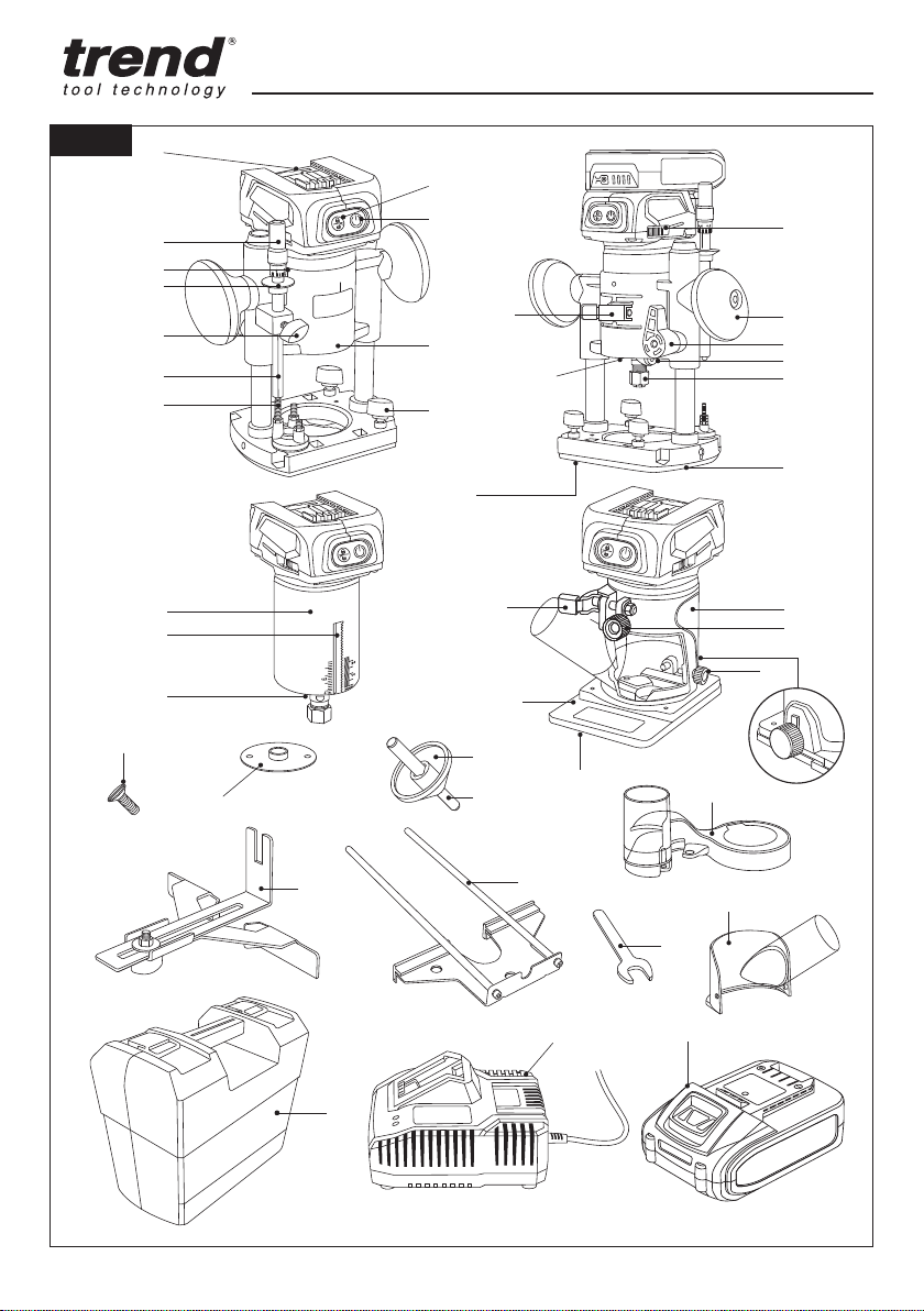
A
M
N
C
F
H
L
V
W
X
DD
NN
Y
EE
FF
HH
JJ
II
GG
KK
MM
OO
PP
Z
D
O
P
S
Q
K
R
T
BB
U
J
E
I
B
G
AA
LL
CC
Fig. 1

T18S/R14
-3-
figure 2
figure 4
figure 4c
figure 3
figure 4b
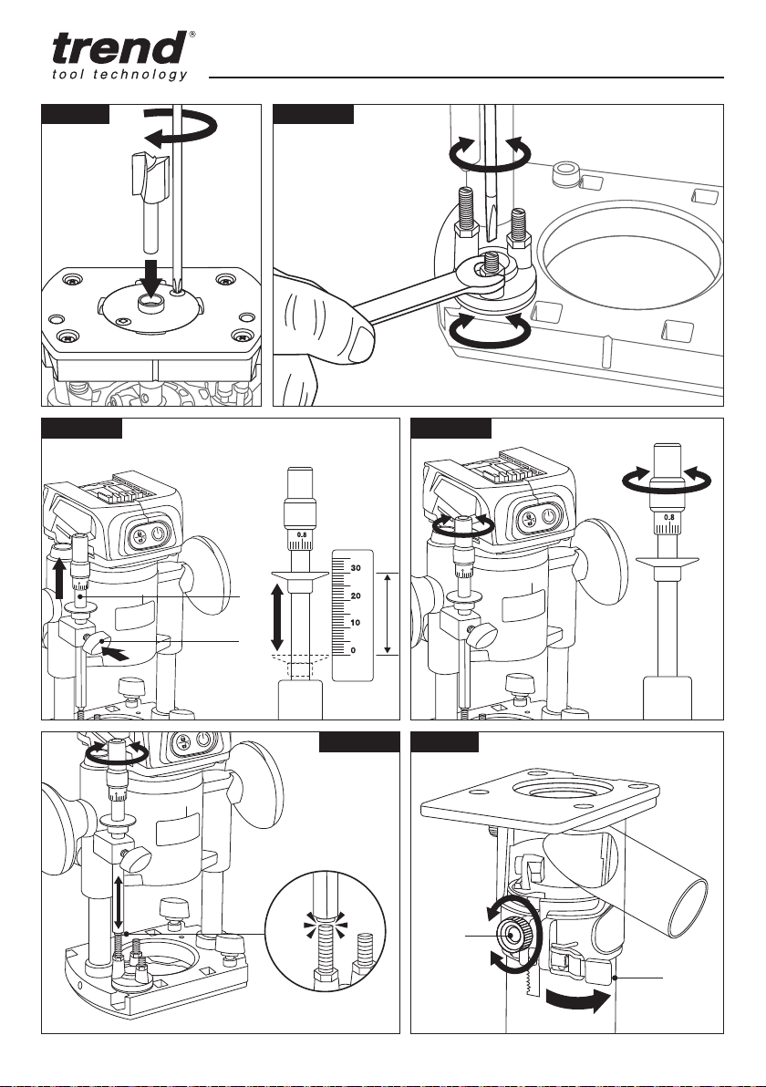
Fig. 2
Fig. 4
Fig. 4b
Fig. 3
figure 4a
Fig. 4a
Fig. 4c
figure 2
figure 2
figure 2a
figure 3a
Fig. 2a
Fig. 3a

T18S/R14
-4-
figure 4d
Fig. 4d
figure5
2
3
figure 6
figure5a
2
3
1
figure 5b
figure 5c
2
3
1
figure 6b
figure 5b
figure 5c
Fig. 5
Fig. 6
Fig. 5a
Fig. 6a
Fig. 5b
Fig. 6b
Fig. 5c

T18S/R14
-5-
figure 7
2
1
1
1
figure 8
figure 8a
figure 10
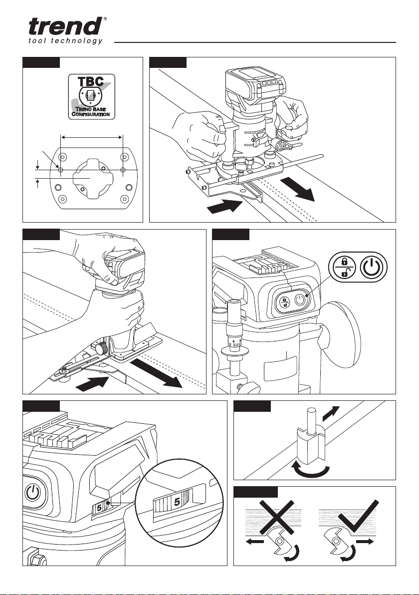
Fig. 7
Fig. 9
Fig. 11 Fig. 11a Fig. 11b
Fig. 8
Fig. 8a
Fig. 10
T18S/R14
-6-
1
2
1
2
Fig. 12
Fig. 13a Fig. 13b
Fig. 14
Fig. 13
Fig. 13c
T18S/R14
-7-
M6
115mm
15mm
figure 16
and 24
1 2
figure 18
1
Fig. 15
Fig. 20
Fig. 20a
Fig. 17 Fig. 18
Fig. 19
Fig. 16

T18S/R14
-8-
2
2
1
figure22
1
2
Fig. 20cFig. 20b
Fig. 21
Fig. 22
1
2
3
4

T18S/R14
-9-
EN - Template
DE - Schablone
FR - Gabarit
NL - Freesmal
SE - Mall
EN - Guide bush
DE - Führungsbuchse
FR - Bague guide
NL - Kopieerring
SE - Styrbussning
EN - Guide bush ring
DE - Führungsbuchsenring
FR - Anneau de douille de guidage
NL - Geleidebus ring
SE - Styrbussring
EN - Cutter
DE - Fräser
FR - Fraise
NL - Frees
SE - Fräs EN - Workpiece
DE - Werkstück
FR - Pièce
NL - Werkstuk
SE - Arbetsstycke
figure23
Fig. 26a
Fig. 23 Fig. 24
figure 16
and 24
D
E
EN - Template
DE - Schablone
FR - Gabarit
NL - Freesmal
SE - Mall
EN - Guide bush fitted to router
DE - Führungsbuchse am
Routermontiert
FR - Douille de guidage montée
sur le routeur
NL - Geleidebus gemonteerd
op bovenfrees
SE - Styrbussning monterad på fräs
d
EN - Formula
DE - Formel
FR - Formule
NL - Formule
SE - Formel
E =(d-D)
2
figure26
Fig. 25 Fig. 26

T18S/R14
-10-
figure26b
Fig. 26b
Fig. 27
This manual suits for next models
2
Table of contents
Languages:
Other TREND Wood Router manuals

TREND
TREND LOCK/JIG/B User manual

TREND
TREND PRT User manual

TREND
TREND CRT/MK3 User manual

TREND
TREND CRT/MK3 User manual

TREND
TREND LOCK/JIG/B User manual

TREND
TREND T-TECH TT/R635 User manual

TREND
TREND T5MK1 V2 User manual

TREND
TREND T5 User manual

TREND
TREND T7E User manual

TREND
TREND 40/15X1/2TC Firmware update
Popular Wood Router manuals by other brands


Clarke
Clarke Contractor CR3 Operation & maintenance instructions

Vision Engraving & Routing Systems
Vision Engraving & Routing Systems 1624R installation guide

Triton
Triton TMNRTR Operating/safety instructions

Status
Status RH1800 Original instructions

Asist
Asist AE4F120DN Instructions for use

Sealey
Sealey SV20 Series manual


