manuals.online logo
Brands
  1. Home
  2. •
  3. Brands
  4. •
  5. Staubli
  6. •
  7. Cables And Connectors
  8. •
  9. Staubli MC4-Evo 2 User manual

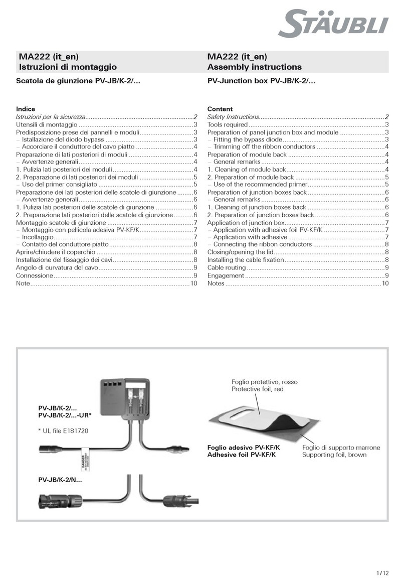
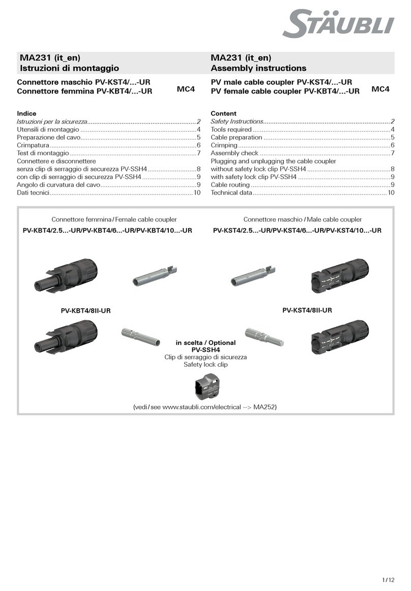
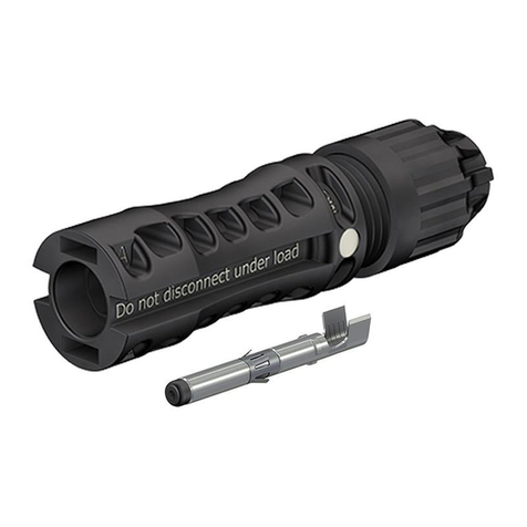
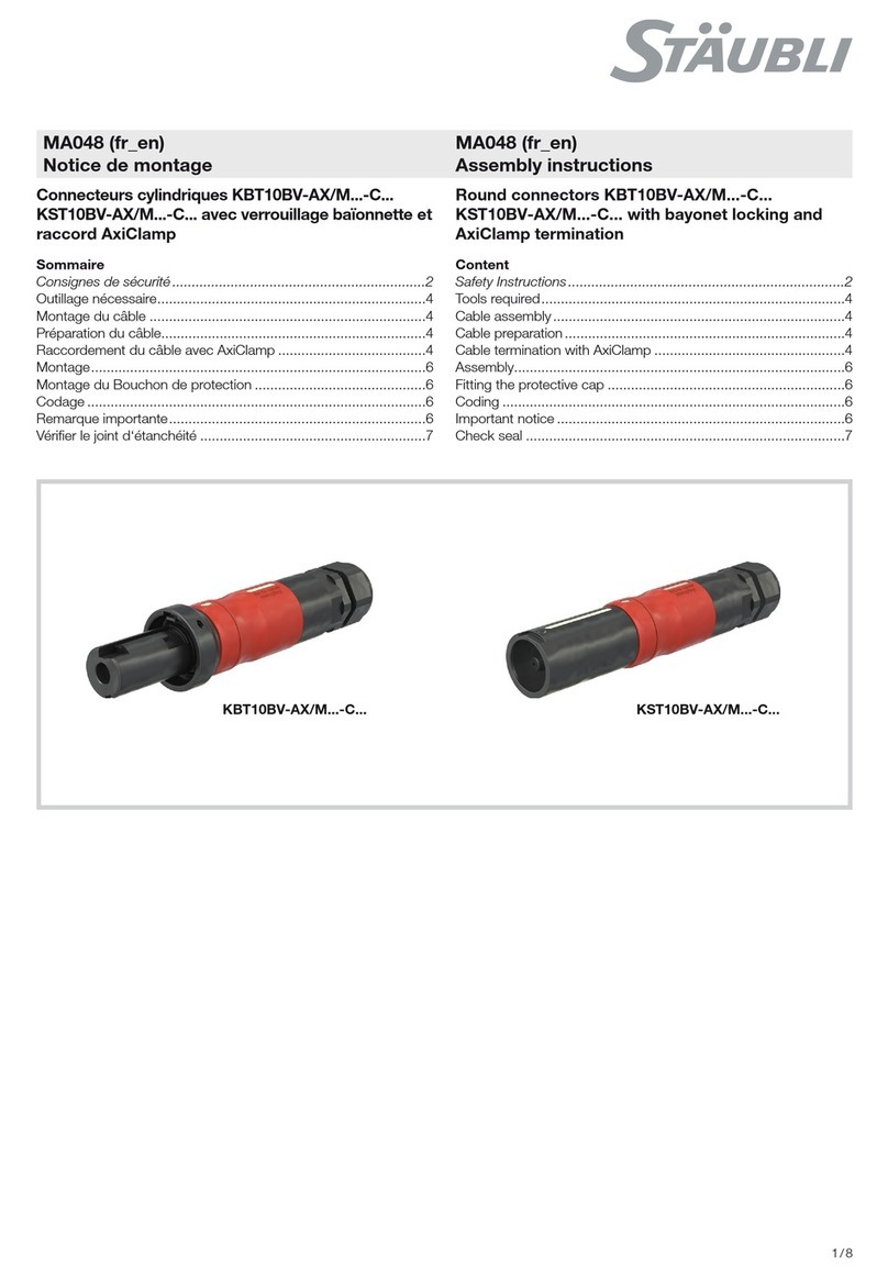
Staubli MC4-Evo 2 User manual

1 / 8
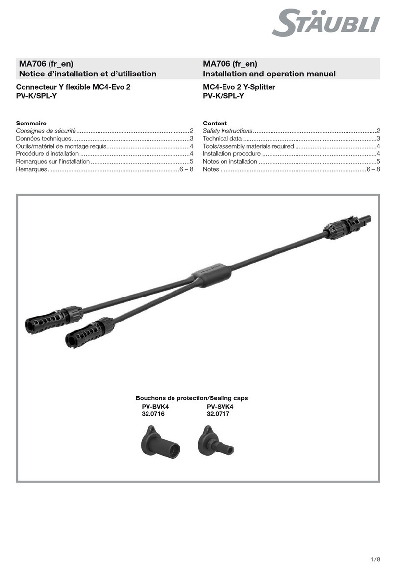
PV-SVK4
32.0717
PV-BVK4
32.0716
MA000 (de_en)
Montageanleitung
MA000 (de_en)
Assembly instructions
MA707 (es_en)
Instalación y operación manual
MA707 (es_en)
Installation and operation manual
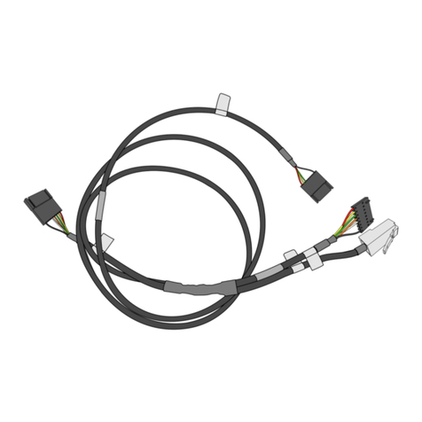
Fusible en línea MC4-Evo 2
PV-K/1500ILF3
MC4-Evo 2 In-line Fuse
PV-K/1500ILF3
Índice
Instrucciones de seguridad����������������������������������������������������������2
Datos técnicos.............................................................................3
Herramientas/materiales de montaje necesarios ..........................4
Procedimiento de instalación .......................................................4
Notas sobre la instalación............................................................5
Notas ....................................................................................6 – 8
Content
Safety Instructions �����������������������������������������������������������������������2
Technical data .............................................................................3
Tools/assembly materials required ...............................................4
Installation procedure ..................................................................4
Notes on installation ....................................................................5
Notes ....................................................................................6 – 8
Tapones/Sealing caps
2 / 82 / 8
Instrucciones de seguridad Safety instructions
Importancia de las instrucciones de montaje
Si NO sigue las instrucciones de montaje y seguridad, pueden
producirse lesiones que pongan en peligro la vida del usuario
debido a descargas eléctricas, arcos eléctricos, incendios o
fallos en el sistema.
•Siga todas las indicaciones de las instrucciones de montaje.
•Utilice e instale el producto únicamente siguiendo las presen-
tes instrucciones de montaje y los datos técnicos.
•Guarde de forma segura las instrucciones de montaje y entré-
guelas a los usuarios posteriores.
Importance of the assembly instructions
NOT following the assembly and safety instructions could result
in life-threatening injuries due to electric shock, electric arcs, fire,
or failure of the system.
•Follow the entire assembly instructions.
•Use and install the product only according to this assembly
instructions and the technical data.
•Safely store the assembly instructions and pass them on to
subsequent users.
Requisitos para el personal
Solo un electricista o una persona con formación en el campo
puede montar, instalar y poner en marcha el sistema.
•Un electricista es toda persona con la formación profesional,
los conocimientos y la experiencia necesarios para identificar
y evitar los peligros que pueden derivarse de la electricidad.
Un electricista debe ser capaz de elegir y utilizar equipos de
protección individual adecuados.
•Una persona con formación en el campo es toda persona ins-
truida o supervisada por un electricista que puede identificar y
evitar los peligros que pueden derivarse de la electricidad.
Requirements for personnel
Only an electrician or electrically instructed person may assem-
ble, install, and commission the system.
•An electrician is a person with appropriate professional
training, knowledge, and experience to identify and avoid the
dangers that may originate from electricity. An electrician is
able to choose and use suitable personal protective equip-
ment.
•An electrically instructed person is a person who is instructed
or supervised by an electrician and can identify and avoid the
dangers that may originate from electricity.
Uso previsto
Los fusibles en línea interrumpen los circuitos de CC en caso de
sobrecorriente.
Intended use
The In-line Fuses interrupt DC circuits in case of over-currents.
Requisitos previos para la instalación y el montaje
•NUNCA utilice un conector de fusible en línea claramente
dañado.
•SOLO debe utilizar herramientas y procedimientos aprobados
por Stäubli.
Prerequisites for installation and assembly
•NEVER use an obviously damaged connector of In-line Fuse.
•ONLY tools and procedures approved by Stäubli shall be
used.
Instalación y montaje seguros
Las piezas conductoras pueden permanecer energizadas una
vez aisladas o desconectadas
•SOLO debe instalar el producto cuando el conjunto fotovoltai-
co o la cadena hayan sido desconectados.
Safe assembly and mounting
Live parts can remain energized after isolation or disconnection
•ONLY Install the product when the photovoltaic-array or -string
is de-energized.
Conexión y desconexión
•Desconecte SIEMPRE el sistema fotovoltaico antes de conec-
tar o desconectar los conectores.
•NUNCA desconecte los conectores cuando existe alguna
carga.
•NUNCA conecte la parte macho o hembra del conector Stäu-
bli con conectores de otros fabricantes.
•NUNCA vuelva a conectar una cadena sin un fusible en línea,
si el fusible en línea ha sido desconectado de esta cadena.
Mating and disconnecting
•ALWAYS de-energize the photovoltaic system before mating
and disconnecting the connectors.
•NEVER disconnect the connectors under load.
•NEVER connect male or female part of Stäubli connector with
connectors of other manufacturers.
•NEVER reconnect a string without an In-line Fuse, if the
In-line Fuse was disconnected from this string.
NO modifique ni repare los componentes
•NO modifique los componentes.
•Sustituya los componentes defectuosos.
Do NOT modify NOR repair component
•Do NOT modify component.
•Replace defective components.
3 / 83 / 8
Datos técnicos Technical data
Denominación del producto Product designation
Longitud en cm
Length in cm
PV-K/1500ILF3y/6E-#
Tensión nominal (gPV) en A
Rated current (gPV) in A
4 = 4 A; 5 = 5 A; 6 = 6 A
15 = 15 A; 20 = 20 A
0059 = 59 cm
Voltaje nominal Voltage rating DC 1500 V
Voltaje de prueba Test voltage 8 kV
Clase de seguridad Safety class II
Categoría de sobrevoltaje/
grado de contaminación
Overvoltage category
Pollution degree
CATIII/3
Temperatura límite superior (ULT) Upper Limiting Temperature (ULT) 115° C
Intervalo de temperatura ambiente Ambient temperature range -40 °C...+50 °C
Grado de protección (IP) Degree of Protection (IP) IP65/IP68 (1 m, 1 h)
Material de aislamiento Insulation material Polyamide/EVA/XLPE
Conectores de acoplamiento
¡Solo se deben emplear conectores
Stäubli originales!
Mating connectors
Only genuine Stäubli
connectors shall be used!
PV-KST4/… o/or PV-KBT4/… (“MC4”)1),
PV-KBT4-EVO 2… o/or PV-KST4-EVO 2… (“MC4-Evo 2”)
Tensión nominal gPV Rated current gPV
4 A
5 A
6 A
15 A
20 A
Rango de temperatura de
transporte/almacenamiento
Transportation/storage
temperature range -40°C a/to +50°C
Certificado TÜV-Rheinland, conforme a
2PfG 2380/10.21
TUV Rheinland certified acc. to
2PfG 2380/10.21 R 60163375
Fusible gPV certificado conforme a
IEC60269-6:2010+Amd1
Fuse link gPV certified acc. to
IEC60269-6:2010+Amd1 J 50524015
1) Atención:
al conectar los conectores, asegúrese de que los valores
asignados (capacidad de corriente y voltaje nominal) de los
productos correspondan a los conectores de acoplamiento
usados. Debe respetarse la información de las instrucciones
de montaje de los conectores usados.
1) Attention:
When connecting the connectors, it must be ensured that
the rated data (current carrying capacity and rated voltage) of
the products are dependent on the mating connectors used.
Observe the information in the assembly instructions for the
connectors used.
4 / 84 / 8
1
23
(fig. 1)
para conectores MC4-Evo 2:
Herramienta de desbloqueo y montaje,
PV-MS-PLS, n.º de pedido 32.6058
(ill. 1)
for MC4-Evo 2 connectors:
Assembly and unlocking tool,
PV-MS-PLS, order No. 32.6058
Nota:
Instrucciones de funcionamiento
MA270, www.staubli.com/electrical
Note:
Operating instructions MA270,
www.staubli.com/electrical
Procedimiento de instalación Installation procedure
RIESGO DE DESCARGA ELÉCTRICA importante
No desconecte el fusible en línea bajo carga ni lo conecte en
un circuito eléctrico que esté bajo carga.
Important ELECTRIC SHOCK HAZARD:
Do not disconnect the In-line Fuse under load nor connect it
in an electrical circuit that is under load.
(fig. 2 – 3)
Con la herramienta de desconexión adecuada, separe el par de
conectores acoplados donde se ubicará el fusible en línea.
(ill. 2 – 3)
Using the appropriate disconnect tool, separate the mated
connector pair where the In-line Fuse will be located.
Herramientas/materiales de montaje necesarios Tools/assembly materials required
Para su integración en un sistema de arnés de cables foto-
voltaicos: For integration into a PV cable harness system:
5 / 85 / 8
Notas sobre la instalación Notes on installation
Notas generales sobre la instalación
•Los conectores no acoplados deben protegerse contra efectos
ambientales (humedad, suciedad, polvo, etc.) con tapones (n.º
de pedido de contacto hembra 32.0716; n.º de pedido de con-
tacto macho 32.0717).
•No acople conectores contaminados.
•Los conectores no deben entrar en contacto con ninguna sus-
tancia química.
General notes on installation
•Unmated connectors must be protected from environmental im-
pact (moisture, dirt, dust, etc.) with sealing caps (socket order
no. 32.0716; plug order no. 32.0717).
•Do not mate contaminated connectors.
•Connectors must not come into contact with any chemicals.
Enrutamiento de cable
El cable debe disponerse de manera tal que como mínimo a 20
mm de la junta el cable no esté sometido a flexión ni a presión.
Consulte las especificaciones de los fabricantes de cables para
conocer el radio de flexión mínimo.
Al instalar en haces (n = >1), deben tenerse en cuenta los rangos
de temperatura del producto y las normas y reglamentos pertinen-
tes.
Cable routing
Cable management must allow a minimum of 20 mm of cable
that exits directly from the cable seal without bending or stress.
Refer to cable manufacturers specification for minimum bending
radius.
When installing in bundles (n = >1), the temperature ratings of
the product and the relevant standards and regulations must be
taken into account.
Conectores contaminados/dañados:
•No permita que el medio ambiente (p. ej., tierra, agua, insectos,
polvo) contamine los conectores.
•No permita que se contamine la superficie de los conectores (p.
ej., pegatinas, pintura, tubo termorretráctil)
•No permita que los conectores entren en contacto directo con al
superficie del revestimiento del techo.
•No permita que los conectores estén en el punto más bajo del
cableado donde se puede acumular agua
•No permita que los conectores queden en agua estancada
•No permita que las bridas se monten directamente en el cuerpo
del conector.
Contaminated/damaged connectors:
•Do not allow connectors to be contaminated by the environ-
ment (e.g. soil, water, insects, dust).
•Do not allow the connector to be contaminated on its surface
(e.g. stickers, paint, heat shrink tubing)
•Do not allow that the connector is directly on the roofing sur-
face.
•Do not allow that the connector is at the lowest point of cabling
where water can collect
•Do not allow that the connector is in standing water
•Do not allow that cable ties to be mounted directly on the
connector body.
Tensión mecánica:
•Verifique que los conectores no estén sometidos a carga de
tracción mecánica permanente ni a vibraciones
•Los conectores no deben someterse a tensión provocada por la
disposición del cable
Mechanical stress:
•Check that the connectors are not subjected to a permanent
mechanical tensile load or vibration
•Connectors shall not be under strain from cable management
Min.
20 mm
6 / 86 / 8
Notas/Notes:
7 / 87 / 8
Notas/Notes:
8 / 88 / 8
© by Stäubli Electrical Connectors AG, Switzerland – MA707 – 07.2022, Index a, Marketing Communications – Sujeto a modificaciones/Subject to alterations
Sede mundial/Global Headquarters:
Stäubli Electrical Connectors AG
Stockbrunnenrain 8
4123 Allschwil/Switzerland
Tel. +41 61 306 55 55
Fax +41 61 306 55 56
mail [email protected]
www.staubli.com/electrical
Notas/Notes:

Other manuals for MC4-Evo 2

13

Other Staubli Cables And Connectors manuals

Staubli CombiTac uniq CT-LMFB-B2/0,5-1,5 AU User manual

Staubli

Staubli CombiTac uniq CT-LMFB-B2/0,5-1,5 AU User manual

Staubli MPC-XA User manual

Staubli

Staubli MPC-XA User manual

Staubli MC PV-KBT3/IV User manual

Staubli

Staubli MC PV-KBT3/IV User manual

Staubli MPC3-BS User manual

Staubli

Staubli MPC3-BS User manual

Staubli Multi-Contact MA213-03 User manual

Staubli

Staubli Multi-Contact MA213-03 User manual

Staubli PV-KST4 UR Series User manual

Staubli

Staubli PV-KST4 UR Series User manual

Staubli ID/S21-C Series User manual

Staubli

Staubli ID/S21-C Series User manual

Staubli CombiTac MA213-03 User manual

Staubli

Staubli CombiTac MA213-03 User manual

Staubli MA403 User manual

Staubli

Staubli MA403 User manual

Staubli CombiTac uniq CT-GOF User manual

Staubli

Staubli CombiTac uniq CT-GOF User manual

Staubli KST6AR-W-N Series User manual

Staubli

Staubli KST6AR-W-N Series User manual

Staubli PV-AZS4 User manual

Staubli

Staubli PV-AZS4 User manual

Staubli PV-ADB4-EVO 2A Series User manual

Staubli

Staubli PV-ADB4-EVO 2A Series User manual

Staubli PV-KBT4-EVO 2 Series User manual

Staubli

Staubli PV-KBT4-EVO 2 Series User manual

Staubli MA273 User manual

Staubli

Staubli MA273 User manual

Staubli MA273 User manual

Staubli

Staubli MA273 User manual

Staubli MA169 User manual

Staubli

Staubli MA169 User manual

Staubli MC Multi-Contact PV-AZS4 User manual

Staubli

Staubli MC Multi-Contact PV-AZS4 User manual

Staubli MA213-05 User manual

Staubli

Staubli MA213-05 User manual

Staubli MA046 User manual

Staubli

Staubli MA046 User manual

Staubli CombiTac direqt User manual

Staubli

Staubli CombiTac direqt User manual

Staubli ID/B16BV-NS-A User manual

Staubli

Staubli ID/B16BV-NS-A User manual

Staubli PV-KBT4 UR Series User manual

Staubli

Staubli PV-KBT4 UR Series User manual

Staubli KBT10BV-AX/M C Series User manual

Staubli

Staubli KBT10BV-AX/M C Series User manual

Popular Cables And Connectors manuals by other brands

Acuity Brands JUNO TF23 installation instructions

Acuity Brands

Acuity Brands JUNO TF23 installation instructions

Blu Stream SC12SP user manual

Blu Stream

Blu Stream SC12SP user manual

SP CONNECT 53218 Mounting instructions

SP CONNECT

SP CONNECT 53218 Mounting instructions

SMART-AVI HDS8P-4K user manual

SMART-AVI

SMART-AVI HDS8P-4K user manual

Tripp Lite N520-152M Specification sheet

Tripp Lite

Tripp Lite N520-152M Specification sheet

BERNSTEIN SEU-1/0-T45 Series instruction manual

BERNSTEIN

BERNSTEIN SEU-1/0-T45 Series instruction manual

Cathrein UFS 800 quick start guide

Cathrein

Cathrein UFS 800 quick start guide

Avenview SPLIT-HDM3D-4 manual

Avenview

Avenview SPLIT-HDM3D-4 manual

Element ELE4023 user manual

Element

Element ELE4023 user manual

Voxx AH731CR manual

Voxx

Voxx AH731CR manual

Techno TH387 Assembly instructions

Techno

Techno TH387 Assembly instructions

KVM Discovery SP-116R user manual

KVM Discovery

KVM Discovery SP-116R user manual

National Instruments IMAQ A8055 installation guide

National Instruments

National Instruments IMAQ A8055 installation guide

Microsoft High Definition AV Pack instruction manual

Microsoft

Microsoft High Definition AV Pack instruction manual

Philips SWV2197W/10 Specifications

Philips

Philips SWV2197W/10 Specifications

Philips SWA4523W Specifications

Philips

Philips SWA4523W Specifications

NAIM HI-LINE manual

NAIM

NAIM HI-LINE manual

Philips Sonicare 300 SerieS Information

Philips

Philips Sonicare 300 SerieS Information

manuals.online logo
manuals.online logoBrands
  • About & Mission
  • Contact us
  • Privacy Policy
  • Terms and Conditions

Copyright 2025 Manuals.Online. All Rights Reserved.