manuals.online logo
Brands
  1. Home
  2. •
  3. Brands
  4. •
  5. Staubli
  6. •
  7. Cables And Connectors
  8. •
  9. Staubli CombiTac uniq CT-GOF User manual

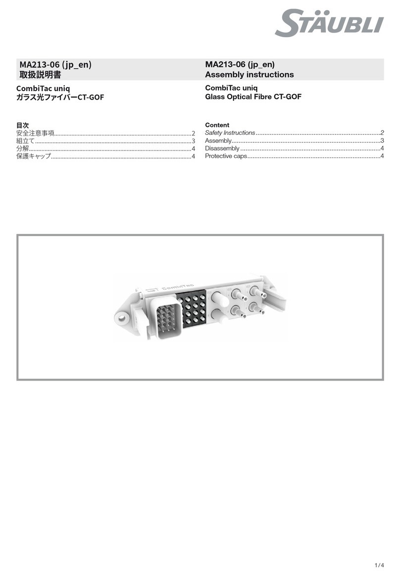
Staubli CombiTac uniq CT-GOF User manual

1 / 4
MA000 (de_en)
Montageanleitung
MA000 (de_en)
Assembly instructions
MA213-06 (it_en)
Istruzioni di montaggio
MA213-06 (it_en)
Assembly instructions
CombiTac uniq
bre ottiche CT-GOF
CombiTac uniq
Glass Optical Fibre CT-GOF
Indice
Istruzioni per la sicurezza������������������������������������������������������������2
Montaggio ���������������������������������������������������������������������������������3
Smontaggio �������������������������������������������������������������������������������4
Cappucci di protezione��������������������������������������������������������������4
Content
Safety Instructions����������������������������������������������������������������������2
Assembly�����������������������������������������������������������������������������������3
Disassembly ������������������������������������������������������������������������������4
Protective caps ��������������������������������������������������������������������������4
2 / 4
Istruzioni per la sicurezza Safety instructions
I prodotti possono essere montati e installati solo da esperti
qualicati e formati, rispettando tutte le disposizioni di sicurez-
za e le norme di legge applicabili�
Stäubli Electrical Connectors (Stäubli) declina qualsiasi re-
sponsabilità derivante dal mancato rispetto delle presenti av-
vertenze�
The products may be assembled and installed exclusively by
suitably qualied and trained specialists duly observing all ap-
plicable safety regulations.
Stäubli Electrical Connectors (Stäubli) does not accept any li-
ability in the event of failure to observe these warnings.
Utilizzare esclusivamente i pezzi e gli attrezzi indicati da Stäu-
bli� Rispettare sempre le procedure qui descritte per la prepa-
razione e il montaggio, poiché in caso contrario non potranno
essere garantiti né la sicurezza né il rispetto delle caratteristi-
che tecniche indicate. Non apportare in nessun modo modi-
che al prodotto�
Use only the components and tools specied by Stäubli. In
case of self-assembly, do not deviate from the preparation and
assembly instructions as stated herein, otherwise Stäubli can-
not give any guarantee as to safety or conformity with the
technical data. Do not modify the product in any way.
I connettori non di fabbricazione Stäubli, che possono essere
collegati con elementi Stäubli e che a volte sono indicati dal
produttore come “compatibili con Stäubli“, non soddisfano i
requisiti per un collegamento elettrico sicuro e stabile nel tem-
po e, per motivi di sicurezza, non possono essere collegati con
elementi Stäubli� Stäubli declina quindi qualsiasi responsabi-
lità nel caso in cui questi connettori non autorizzati da Stäubli
vengano collegati con elementi Stäubli e causino quindi dei
danni�
Connectors not originally manufactured by Stäubli which can
be mated with Stäubli elements and in some cases are even
described as ”Stäubli-compatible” by certain manufacturers
do not conform to the requirements for safe electrical connec-
tion with long-term stability, and for safety reasons must not
be plugged together with Stäubli elements. Stäubli therefore
does not accept any liability for any damages resulting from
mating such connectors (i.e. lacking Stäubli approval) with
Stäubli elements�
I lavori qui descritti non possono essere eseguiti su
pezzi sotto tensione o corrente.
The work described here must not be carried out
on live or load-carrying parts.
La protezione da scosse elettriche deve essere ga-
rantita nel prodotto nale e accertata dall’utente.
Protection from electric shock must be assured by
the end product (i.e. by the correctly assembled
plug connector) and by its user.
I connettori non possono essere staccati sotto ca-
rico. È consentito collegare e staccare i connettori
sotto tensione.
The plug connections must not be disconnected
under load. Plugging and unplugging when live is
permitted.
Il connettore dovrebbe essere controllato ad ogni
utilizzo per escludere qualsiasi difetto esterno (in
particolare dell’isolamento). In caso di dubbi sulla
sicurezza dello stesso, vi chiediamo di consultare
uno specialista o di sostituire il prodotto.
Each time the connector is used, it should previously
be inspected for external defects (particularly in the
insulation). If there are any doubts as to its safety, a
specialist must be consulted or the connector must
be replaced.
I connettori a innesto nella scatola sono protetti
dall’acqua secondo la classe di protezione IP indica-
ta per il prodotto in questione.
The plug connectors in the housing are protected
from water in accordance with the IP protection
class stated for the relevant product.
Proteggere i connettori non utilizzati da umidità e
sporco. I connettori sporchi non possono essere
collegati tra loro.
Unmated plug connectors must be protected from
moisture and dirt. The male and female parts must
not be plugged together when soiled.
Ulteriori caratteristiche tecniche sono indicate nel
catalogo del prodotto. For further technical data please see the product
catalogue.
Spiegazione dei simboli Explanation of the symbols
Pericolo! Voltaggi pericolosi Warning of dangerous voltages
Pericolo! Area pericolosa Warning of a hazard area
Consiglio utile Useful hint or tip
3 / 43 / 4
1
2
3
Montaggio Assembly
Hinweis:
L’assemblaggio di contatti a
bre ottiche deve essere effettuato
solo da personale specializzato che
dispone dell’attrezza-tura adeguata�
Per crimpare la bussola di ssag-
gio si consiglia di utilizzare una
pinza di crimpatura esagonale con
un’apertura della chiave di 3,3mm.
Note:
The assembly of glass bre con-
tacts must be carried out by special-
ised personnel with the appropriate
equipment. For crimping the reten-
tion sleeve, a crimping tool with a
hexagonal form and a wrench size of
3.3mm is recommended..
(ill. 1)
Inserire lateralmente il cavo assembla-
to nella piastra di supporto�
Tirare indietro i cavi nché i contatti
non sono posizionati all‘interno della
piastra di supporto�
(ill. 1)
Insert assembled cable laterally into
the holding plate�
Pull back cable until contacts are posi-
tioned in the holding plate�
(ill. 2)
Spingere i contatti e la piastra di
supporto nel porta contatti, facendo
attenzione che siano posizionati cor-
rettamente (1-4)�
(ill. 2)
Push contacts into the contact carrier
with the holding plate.
Make sure that they are correctly
positioned� (1-4)
(ill. 3)
Premere la piastra di supporto sul
porta contatti nché non si sentono
scattare le linguette di ssaggio.
(ill. 3)
Press holding plate towards the con-
tact carrier until retaining latches have
both engaged audibly�
Attenzione
Controllare la posizione corretta!
Attention
Check correct position!
4 / 44 / 4
7
4
6
S
8
S
5
Fabbricante/Producer:
Stäubli Electrical Connectors AG
Stockbrunnenrain 8
4123 Allschwil/Switzerland
Tel. +41 61 306 55 55
Fax +41 61 306 55 56
mail [email protected]
www.staubli.com/electrical
© by Stäubli Electrical Connectors AG, Switzerland – MA213-06 – 01.2017, Index a, Marketing Communications – Salvo modiche / Subject to alterations
Smontaggio Disassembly
(ill. 4)
Piegare leggermente verso l‘esterno le
linguette di ssaggio. A seconda della
posizione, è possibile aiutarsi con un
cacciavite�
(ill. 4)
Bend the retaining latch slightly out-
wards. Depending on the installation
position, a screwdriver may be used.
(ill. 5)
Esercitare una pressione sui contatti
dal lato di connessione nché la pias-
tra di supporto non viene spinta fuori.
Ripetere l‘operazione per la seconda
linguetta di ssaggio.
(ill. 5)
From the plugging side, exert pressure
on the contacts until the holding plate
is pushed out of the retention. Repeat
operation on the second retaining
latch�
(ill. 6)
Estrarre la piastra di supporto con
i contatti dal porta contatti� In caso
di contatti maschi, si consiglia di
esercitare una pressione sui contatti
utilizzando un contatto femmina non
assemblato. In questo modo è possi-
bile esercitare una pressione maggiore
e proteggere anche la supercie termi-
nale delle bre da danni e sporcizia.
(ill. 6)
Pull holding plate out of the contact
carrier with the contacts. When deal-
ing with pin contacts, it is recom-
mended to exert pressure on the
contacts with an unassembled socket
contact� This enables greater pressure
to be exerted and protects the end
surface of the bres from damage and
dirt�
Cappucci di protezione Protective caps
Contatti pre-assemblati con cap-
puccio di protezione (ill. 7-8) Pre-assembled contacts with pro-
tective caps (ill. 7-8)
Attenzione
Togliere tutti i cappucci di protezi-
one (S) prima della connessione�
Attention
Before plugging, remove all the
protective caps (S)�

Other Staubli Cables And Connectors manuals

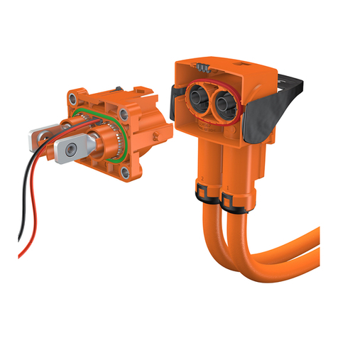
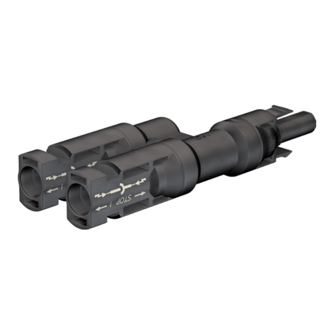
Staubli PV-AZS4 User manual

Staubli

Staubli PV-AZS4 User manual

Staubli PerforMore User manual

Staubli

Staubli PerforMore User manual

Staubli PV-ADB4-EVO 2A Series User manual

Staubli

Staubli PV-ADB4-EVO 2A Series User manual

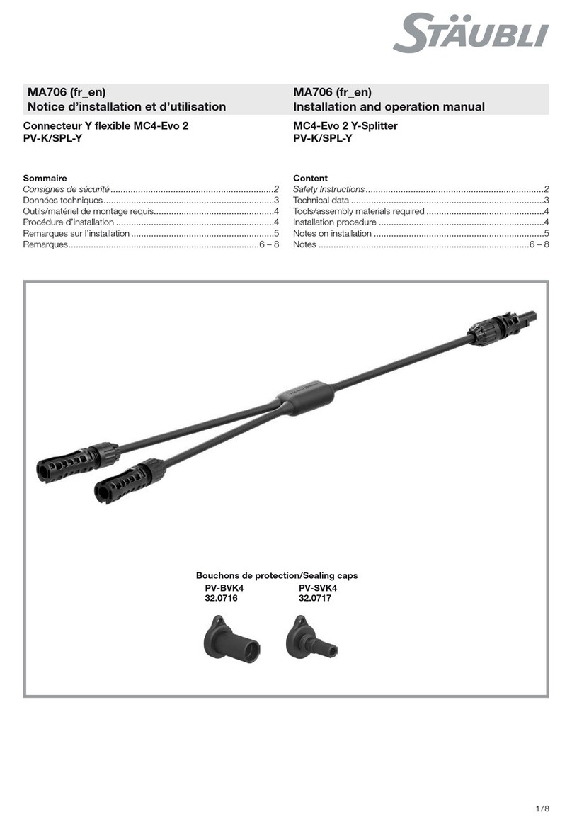
Staubli MC4-Evo 2 PV-K/SPL-Y User manual

Staubli

Staubli MC4-Evo 2 PV-K/SPL-Y User manual

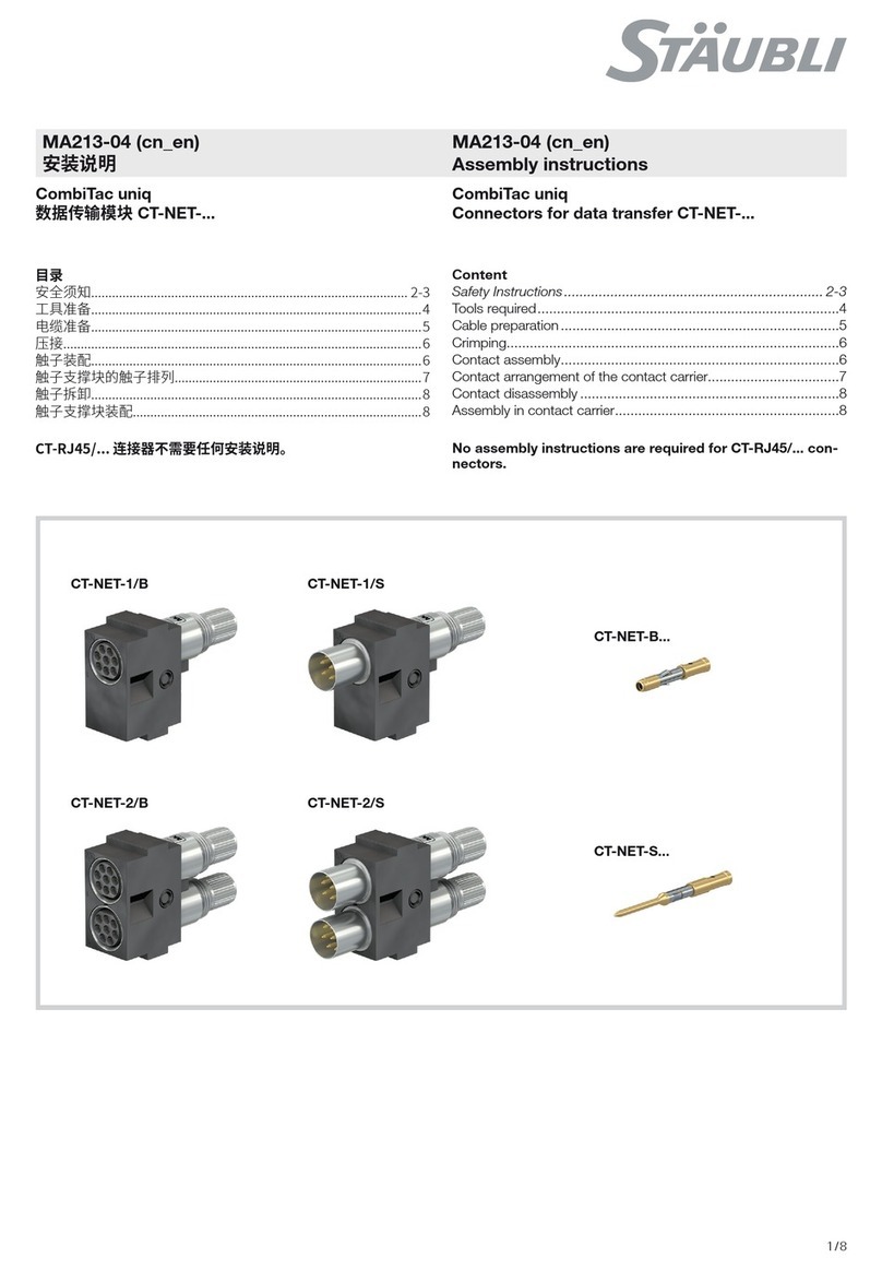
Staubli CombiTac uniq CT-NET Series User manual

Staubli

Staubli CombiTac uniq CT-NET Series User manual

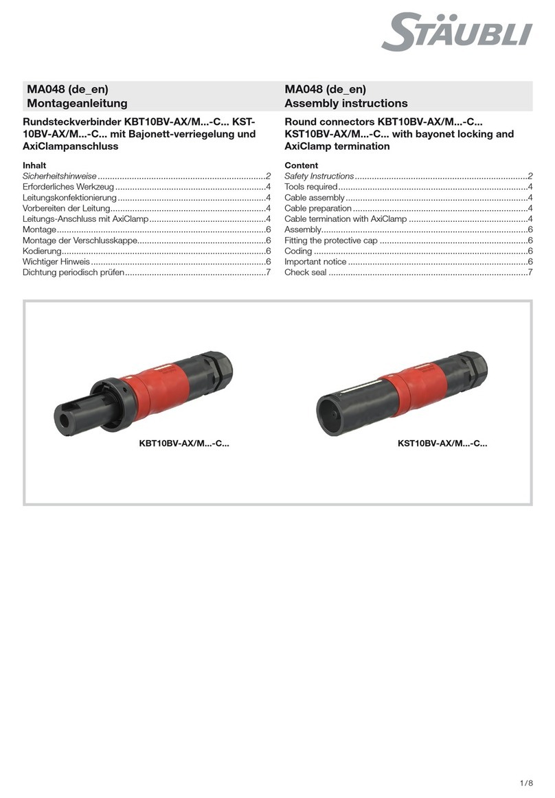
Staubli KST10BV-AX/M C Series User manual

Staubli

Staubli KST10BV-AX/M C Series User manual

Staubli MA273 User manual

Staubli

Staubli MA273 User manual

Staubli CombiTac MA213-06 User manual

Staubli

Staubli CombiTac MA213-06 User manual

Staubli MC4-Evo 2 User manual

Staubli

Staubli MC4-Evo 2 User manual

Staubli PV-KST4 UR Series User manual

Staubli

Staubli PV-KST4 UR Series User manual

Staubli MPC3-BS User manual

Staubli

Staubli MPC3-BS User manual

Staubli MC4-Evo 2 User manual

Staubli

Staubli MC4-Evo 2 User manual

Staubli 16BL-CP User manual

Staubli

Staubli 16BL-CP User manual

Staubli PV-ADB4-EVO 2 UR Series User manual

Staubli

Staubli PV-ADB4-EVO 2 UR Series User manual

Staubli MA713 User manual

Staubli

Staubli MA713 User manual

Staubli Multi-Contact ID/B16BV-NS-A User manual

Staubli

Staubli Multi-Contact ID/B16BV-NS-A User manual

Staubli MA046 User manual

Staubli

Staubli MA046 User manual

Staubli PV In-Line-Fuse User manual

Staubli

Staubli PV In-Line-Fuse User manual

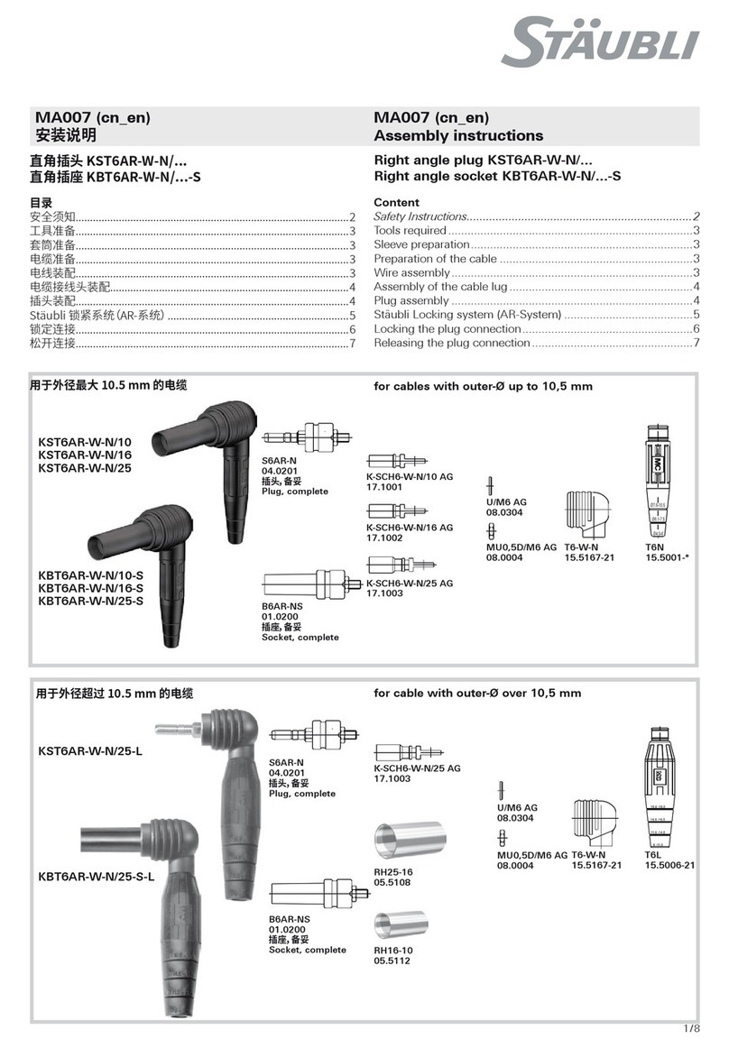
Staubli KST6AR-W-N Series User manual

Staubli

Staubli KST6AR-W-N Series User manual

Staubli KBT16BV-NS/M Series User manual

Staubli

Staubli KBT16BV-NS/M Series User manual

Staubli MC4-Evo 2 User manual

Staubli

Staubli MC4-Evo 2 User manual

Staubli KBT21/M40 C Series User manual

Staubli

Staubli KBT21/M40 C Series User manual

Staubli PV-KBT4-EVO ST Series User manual

Staubli

Staubli PV-KBT4-EVO ST Series User manual

Staubli PV-KST4 UR Series User manual

Staubli

Staubli PV-KST4 UR Series User manual

Popular Cables And Connectors manuals by other brands

Philips SWV6367 Specifications

Philips

Philips SWV6367 Specifications

mfe ESC 650 user manual

mfe

mfe ESC 650 user manual

PowerBridge ONE-PRO-6 manual

PowerBridge

PowerBridge ONE-PRO-6 manual

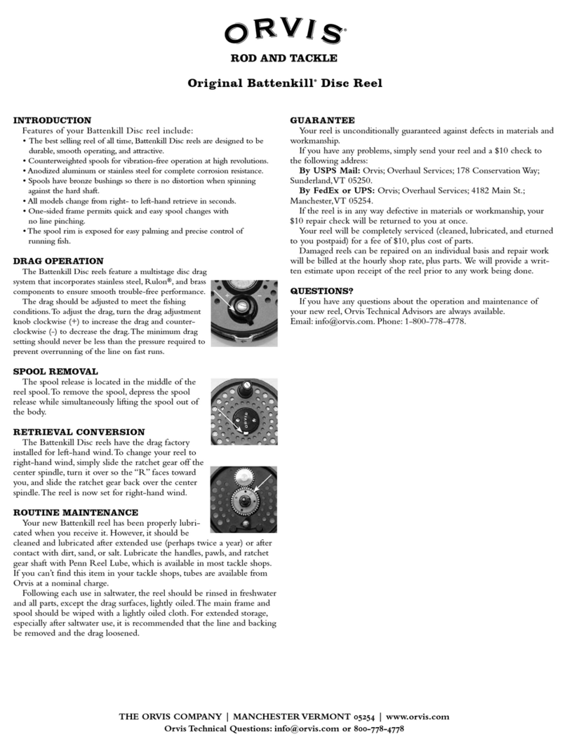
ORVIS Battenkill quick start guide

ORVIS

ORVIS Battenkill quick start guide

ELEY 1045 Assembly/installation instructions

ELEY

ELEY 1045 Assembly/installation instructions

Volkswagen V.A.G 1598/43-1 operating manual

Volkswagen

Volkswagen V.A.G 1598/43-1 operating manual

nVent RAYCHEM T-100 manual

nVent RAYCHEM

nVent RAYCHEM T-100 manual

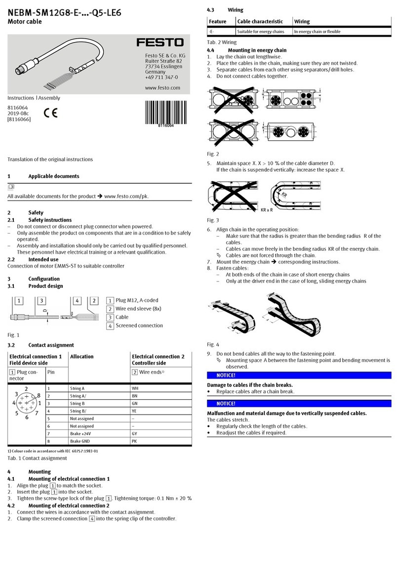
Festo NEBM-SM12G8-E Q5-LE6 Series Instructions & assembly

Festo

Festo NEBM-SM12G8-E Q5-LE6 Series Instructions & assembly

nedis VSPL34716AT quick start guide

nedis

nedis VSPL34716AT quick start guide

Atim Cloud Wireless ACW/LW8-DINRSM user guide

Atim Cloud Wireless

Atim Cloud Wireless ACW/LW8-DINRSM user guide

Philips IMAGEO 69134/55/PH brochure

Philips

Philips IMAGEO 69134/55/PH brochure

PS Audio XStream instruction manual

PS Audio

PS Audio XStream instruction manual

PCB Piezotronics IMI SENSORS 009M205/100 Installation and operating manual

PCB Piezotronics

PCB Piezotronics IMI SENSORS 009M205/100 Installation and operating manual

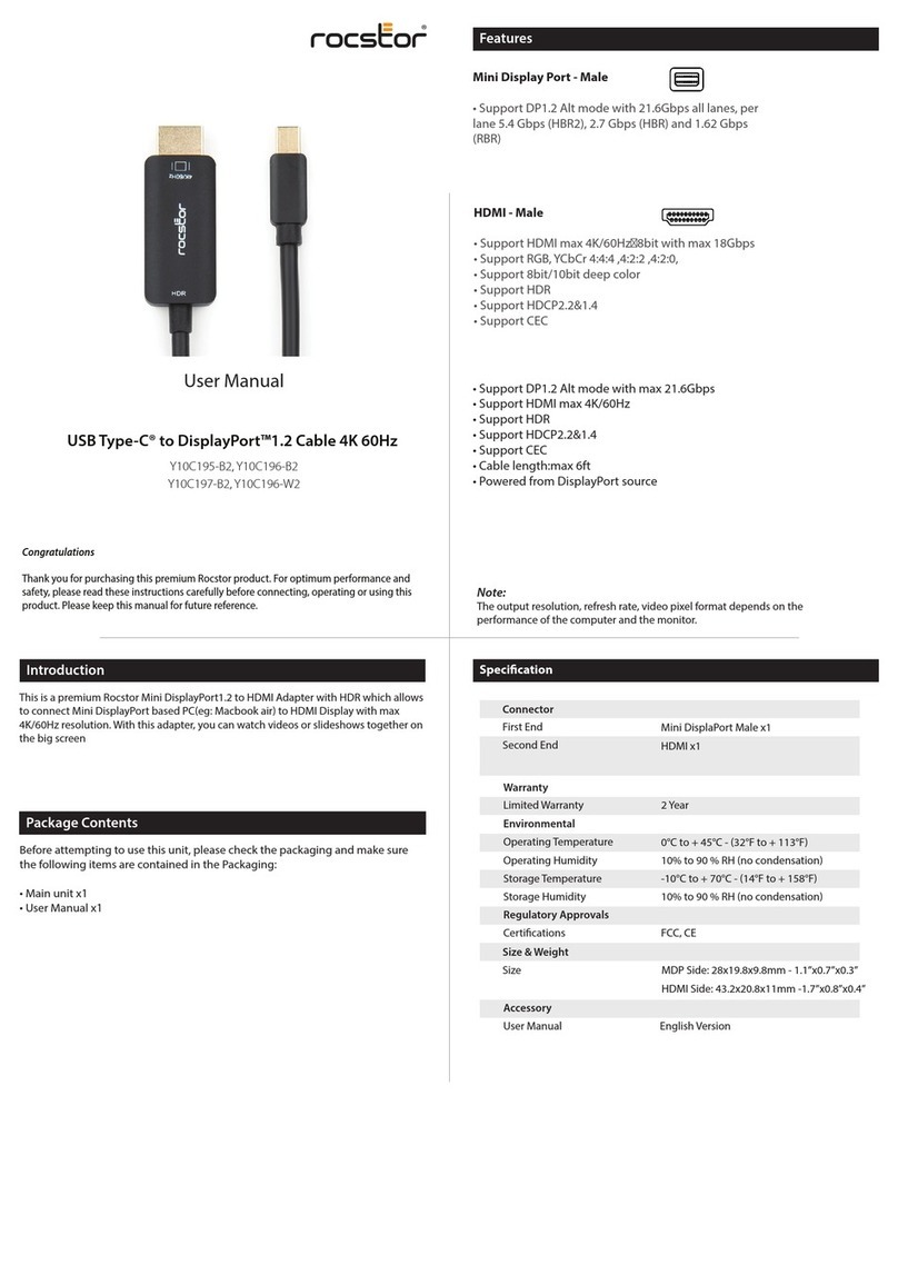
Rocstor Y10C195-B2 user manual

Rocstor

Rocstor Y10C195-B2 user manual

Manhattan 150712 install guide

Manhattan

Manhattan 150712 install guide

enphase CT-200-SOLID Quick install guide

enphase

enphase CT-200-SOLID Quick install guide

Tripp Lite N125-050-GY Specifications

Tripp Lite

Tripp Lite N125-050-GY Specifications

Rean RCAC3M-X-000 Assembly instruction

Rean

Rean RCAC3M-X-000 Assembly instruction

manuals.online logo
manuals.online logoBrands
  • About & Mission
  • Contact us
  • Privacy Policy
  • Terms and Conditions

Copyright 2025 Manuals.Online. All Rights Reserved.