ENGLISH
8
8
- In start-up or during operation of the engine, never
touch hot parts such as the muer, the high voltage
wire or the spark plug.
- After the engine has stopped, the muer is still hot.
Never place the machine in any places where there
are ammable materials (dry grass, etc.), combustible
gasses or combustible liquids.
- Pay special attention to operation in the rain or just
after the rain as the ground may be slippery.
- If you slip or fall to the ground or into a hole, release the
throttle lever immediately.
6 PETROL SAFETY WARNINGS
WARNING: Use extra care when handling fuels.
They are inammable and the vapours are
potentially explosive. The following points
must be observed.
- Use only an approved container.
- Never remove the fuel cap or add fuel with the power
source running. Allow engine exhaust components to
cool before refuelling.
- Do not smoke.
- Never refuel the machine indoors.
- Never store the machine or fuel containers inside,
where is an open ame, such as a water heater.
- If fuel is spilled, do not attempt to start the power
source, but move the machine away from the area of
spillage before starting.
- Always replace and securely tighten the fuel cap after
refuelling.
- If the tank is drained, this should be done outdoors.
- Keep the handles free from oil and fuel.
- Do not smoke while mixing fuel or lling tank.
- Never start or run the engine inside a closed room
or building. Exhaust gas contains dangerous carbon
monoxide.
- Never attempt to make engine adjustments while the
unit is running and strapped to the operator. Always
make engine adjustments with the unit resting on a at,
clear surface.
- When the machine is placed in storage for a long time,
drain fuel from the fuel tank and carburettor, clean the
parts, move the machine to a safe place and conrm
that the engine is cooled down.
7 SPECIFIC SAFETY WARNINGS
- BLADE CAN RECOIL VIOLENTLY FROM MATERIAL
IT CANNOT CUT – Blade can cause you to lose arms
or legs. Keep people and animals 30 feet (10 meters)
away in all directions. If blade contacts foreign objects
during operation, turn o engine and allow blade to
come to a halt. Then check blade for damage. Always
discard blade if it is warped or cracked.
- BLADE CATAPULTS OBJECTS THROUGH AIR -
You can be blinded or injured. Wear eye, face, and
leg protection. Always clear work area of any foreign
objects before using blade. Keep people and animals
10 metres away in all directions.
- BLADE COASTS AFTER THROTTLE IS RELEASED -
A coasting blade can injure you or bystanders. Before
servicing the blade, always turn o engine, and be sure
coasting blade has stopped.
- WARNING DO NOT USE ANY OTHER FUEL than
that recommended in your manual. Always follow
instructions in the Fuel and Lubrication section of this
manual. Never use petrol unless it is properly mixed
with 2-cycle engine lubricant. Permanent damage to
engine will result, voiding manufacturer’s warranty.
- DO NOT USE ANY OTHER CUTTING ATTACHMENT.
Only use our replacement parts and accessories, which
are designed specically to enhance the performance
and maximize the safe operation of our products.
Failure to do so may cause poor performance and
possible injury. Use only the stringhead supplied with
this product. Do not use any other cutting attachment.
Use of such attachments will void your factory warranty
and may result in serious bodily injury.
8 FUEL AND LUBRICATION
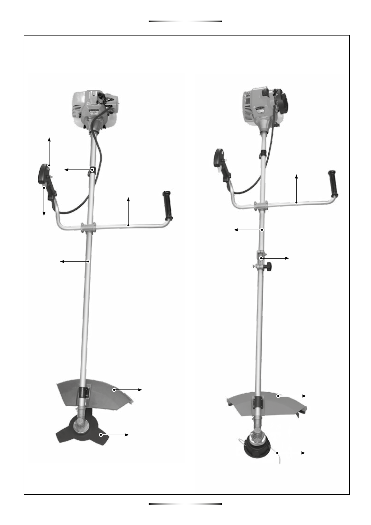
8.1 Bike handle installation (Fig. 1)
- Install the U-handle on the xing holder, install the
clamp and fasten with the screws.
8.2 Installation of the toolbar
- Removable bar allows easy transportation. Mount the
connecting rod 16 pressing and rotating until the pin
to penetrate into the hole in the bar. Once the pin A is
within tighten handle B
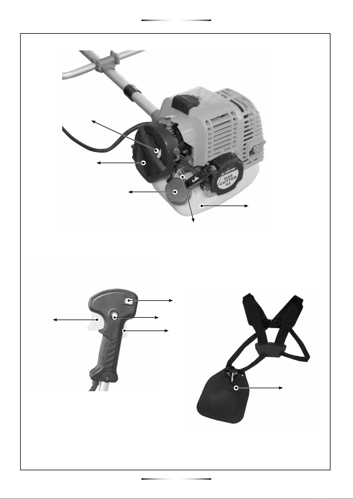
8.3 Installing the protection (Fig. 2)
- Remove the 2 screws on the shield.
- East threaded holes with respect to the bar that is
balanced and oating.
- Adjust the harness straps so that the carabiner is level
Hip
8.4 Installing the harness (Fig. 3)
- Adjust the harness hanger in a comfortable position.
- Buckle the harness at the hanger.
8.5 Replace the metal blade to spool
CAUTION: NEVER use unit if blade is warped
or has teeth that are chipped or missing. Re-
place a damaged blade immediately.
CAUTION: Always wear heavy-duty work glo-
ves when handling and installing a blade.
8.5.1 Disassembly metal blade
- Align the hole on the gear box to the slot on the ange
washer
- Use the pin to go through the hole and slot, and hold
the ange washer
- Loose the nut and remove the metal blade and cup
washer