- 12 - - 13 -
GB
1. About this document
– Please read carefully and keep in a
safe place.
– Under copyright.
Reproduction either in whole or in part
only with our consent.
– Subject to change in the interest of
technical progress.
Symbols
!Hazard warning!
...
Reference to other information
in the document.
2. General safety precautions
Disconnect the power supply
before attempting any work on
the sensor.
• This product may only be installed by a
qualified electrician in accordance with
national wiring regulations as defined in
VDE 08 29 (DIN EN 5000 90).
• Fitted improperly, low-voltage instal-
lations can cause extremely serious
personal injury or damage to property.
• This product must never be con-
nected to a 230 V AC power supply
as it is intended for connection to an
extra-low voltage power supply.
• Only use genuine replacement parts.
• Repairs may only be made by special-
ist workshops.
3. True Presence®KNX
Proper use
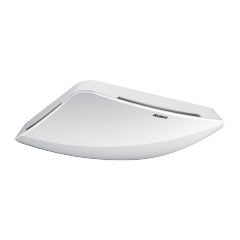
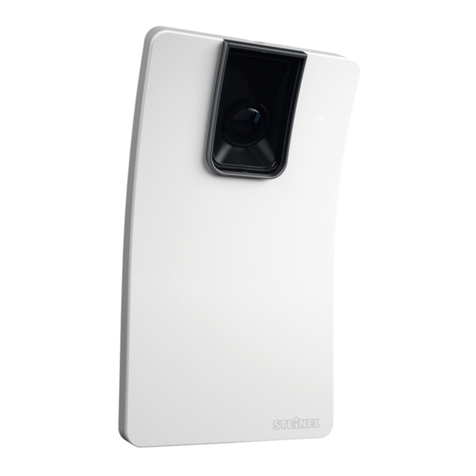
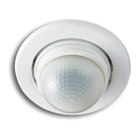
– Sensor for indoor ceiling mounting for
connecting to the KNX bus system
The True Presence KNX is the “eyes and
ears” in modern, intelligent buildings.
Presence of persons, brightness, room
temperature and humidity are captured
as sensor variables.
The True Presence KNX is also equipped
with “True Presence” technology which
detects the presence of persons. Thus,
true presence and absence is recognisa-
ble. The detection zone of the sensor can
be precisely limited via the range setting.
All function settings are made via the
Engineering Tool Software (ETS) from
version ETS4.0 and higher.
The Smart Remote app displays the
sensor variables and enables activation
of the programming mode.
Product components
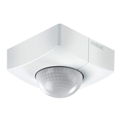
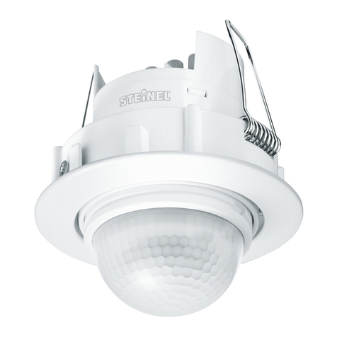
concealed installation (Fig.3.1)
– Sensor
– Surround
Product components
surface-mounted installation (Fig.3.2)
– Sensor
– Surround
– Surface-mounting adapter
Product dimensions, concealed installa-
tion (Fig. 3.3)
Product dimensions, surface-mounted
installation (Fig.3.4)
Detection zone (Fig. 3.5)
!
Note:
Surface-mounted installation has influ-
ences on the sensor variables measured.
For this reason, correction factors are
implemented in the software which take
effect by activating the "surface mount-
ing" type of installation in the ETS.
6. Function and settings
Factory settings
– See KNX application description
Startup
During initial commissioning, the pres-
ence detector creates a room image. The
room must be free of movement for 2 to
2.5 minutes for this.
Note:
An image of the room is also created if
reach or mounting height is changed.
The sensitivity of the True Presence
sensor can be adjusted from 1 (= low) to
9 (= high) via the ETS.
The functions to be used (activated) are
set in the "General Settings" parameter
window using the ETS.
Note:
You will find an application description at
knx.steinel.de.
1. Issue physical address and generate
application program in the ETS.
2. Load the physical address and appli-
cation program into the True Presence
sensor. When you are prompted,
press the programming button A
(Fig. 4.1).
4. Installation
Wiring diagram (Fig. 4.1)
5. Mounting
• Check all components for damage.
• Do not use the product if it is dam-
aged.
• Select an appropriate mounting loca-
tion, taking the reach and presence
detection into consideration.
• Switch OFF power supply (Fig.4.1)
Mounting procedure, concealed
installation
– Firmly screw the surround onto the
mounting box (Fig 5.1)
– Make plug connection (Fig.5.2)
– Position sensor on the surround
(Fig. 5.3)
• The sensor is held on the surround by
magnetic force.
Mounting procedure, surface-
mounted installation
– Drill holes and screw on sur-
face-mounting adapter (Fig. 5.4)
– When mounting with exposed cable,
break out the mounting tab (Fig. 5.4)
– Firmly screw the surround onto the
surface-mounting adapter (Fig 5.5)
– Make plug connection (Fig.5.6)
– Position sensor on the surround
(Fig. 5.7)
• The sensor is held on the surround by
magnetic force.
Note:
When setting the reach, the mounting
height needs to be specified via the ETS
GB
