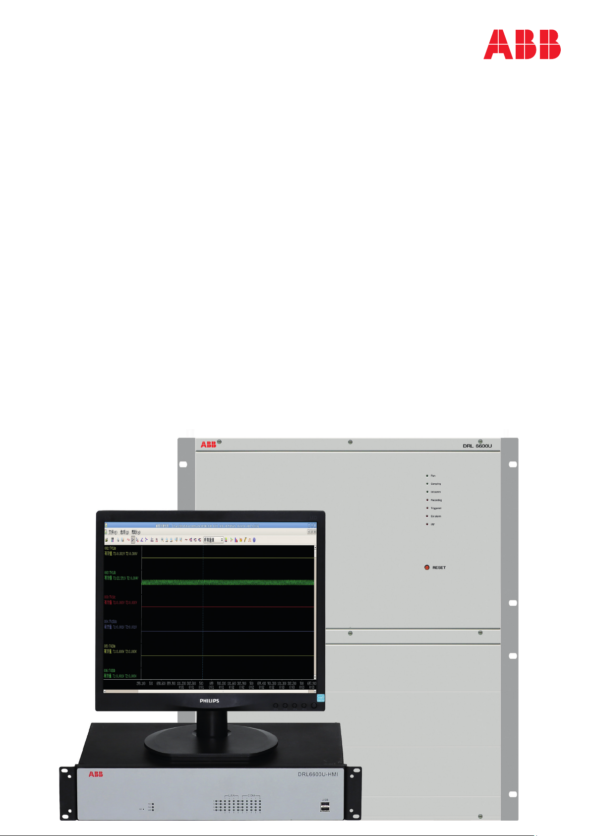
Disturbance Recording and Fault Locating Device DRL6600U
7. Rate-of-change frequency
recording
Power system operation has a high requirement for
frequency stability. Subtle frequency changes can
cause huge damage to generators and other electrical
equipment. The DRL6600U can truthfully record
abnormal changes of high frequency, low frequency
and frequency change rate in the power system. It is
widely adopted in power plants, substations, and for
industrial use.
8. Binary signal recording
Crucial binary signal indication information such as
protection operation, reclosing operation and change of
breaker indication can be recorded. Furthermore, the
recorded information reflects the whole process of one
complete disturbance so that crucial operation
information such as false tripping, breaker failure or
reclosing failure can be analyzed.
9. Fault Locating
Fault location by impedance measurement calculates
the linear impedance between the terminal and the fault
location, and in turn determines the distance to the
disturbance.
When the corresponding parameters like line length
and line impedance have been entered, once a phase-
to-ground or phase-to-phase short circuit happens a
recording will be started. Based on the impedance at
the time the short circuit happens, the DRL6600U
automatically calculates and determines the distance
between the device and the fault point.
10. Data analysis
DRL6600U provides a cross-platform waveform
analysis tool, available in both Windows and Linux
operation systems.
With a convenient and fast channel selecting mode, it's
able to show any selected signal on the same page,
and to compare and analyze currents and voltages of
different intervals, and different binary signals.
It can display several modes such as showing
instantaneous, RMS or phasor values. It adopts to
many advanced analysis functions such as sequence
components, power calculation, harmonics calculation,
location and aperiodic component.
With waveform copy and paste functions it's convenient
and fast to select and re-save the required channels of
the record, and then form new waveform files for
accident analysis and fault location.
Direct shortcut keys and tool tips bring users
convenience to operate all software functions.
Through the frequency following mode, accurate
values of analog signals deviating from 50Hz can be
acquired.