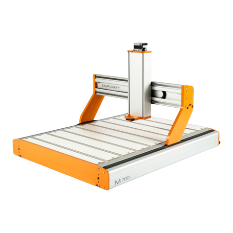
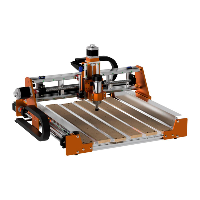
STEPCRAFT M Series User manual

1
Operating Manual
Freestyle Milling™
Translation of the original operating
manual Freestyle Milling™
Date of: 08-25-2020
CNC System
STEPCRAFT M-Series
Call for consumer information
Customers from outside the U.S.
STEPCRAFT GmbH & Co. KG
An der Beile 2
58708 Menden
Germany
Phone: +49 (0) 2373-179 11 60
E-mail: info@stepcraft-systems.com
Customers from the U.S. / Canada
STEPCRAFT Inc.
59 Field Street, Rear Building
Torrington, CT, 06790
United States
Phone: 001-203-5561856
E-mail: info@stepcraft.us

NOTICE
All instructions, warranties and other collateral documents are subject to change at the sole discretion of
STEPCRAFT GmbH & Co. KG. For up-to date product literature, visit www.stepcraft.us for customers from North
America and Mexico or www.stepcraft-systems.com for customers from the rest of the world and click on the service
tab for this product.
SAVE ALL WARNINGS AND INSTRUCTIONS FOR FUTURE REFERENCE.
Meaning of Special Language
The following terms are used throughout the product literature to indicate various levels of potential harm when
operating this product: The purpose of safety symbols is to attract your attention to possible dangers. The safety
symbols, and their explanations, deserve your careful attention and understanding. The safety warnings themselves
do not eliminate any danger. The instructions or warnings they give are not substitutes for proper accident prevention
measures.
NOTICE
Procedures which, if not properly followed, create a possibility of physical property damage AND
a little or no possibility of injury.
CAUTION
Procedures which, if not properly followed, create a probability of physical property damage AND
a possibility of serious injury.
WARNING
Procedures which, if not properly followed, create a probability of property damage, collateral
damage, serious injury or death OR create a high probability of superficial injury.
Safety Alert: Indicates caution or warning. Attention is required to avoid serious personal injury.
Read the ENTIRE instruction manual to become familiar with the features of the product and how
to operate them. Failure to operate the product correctly can result in damage to the product,
personal property and cause serious injury, electric shock and/or fire.

3
CONTENT
1. Introduction .....................................................................................................................4
2. Safety Instructions and Protective Measures...................................................................4
2.1 General Safety Warnings for the Use of Power Tools...............................................4
2.2 Additional Safety Instructions for Freestyle MillingTM ................................................5
2.3 Protective Measures.................................................................................................6
2.4 Personal Protective Equipment ................................................................................7
2.5 Emergency Stop Switch ...........................................................................................7
2.6 Residual Risk ...........................................................................................................7
2.7 Safety Symbols ........................................................................................................8
3. Preparations for Freestyle Milling™..................................................................................8
3.1 Installation of the Vacuum Panels ............................................................................8
3.2 Suitable Workpiece Surfaces ...................................................................................9
3.3 Installation of the Machine Safety Kit......................................................................10
3.4 Attaching the Machine to the Workpiece (General Information)..............................11
3.5 Securing the Machine on a Wall (Example)............................................................13
4. Instructions on Freestyle Milling™..................................................................................14
5. Additional Maintenance Works ......................................................................................15
6. Contact..........................................................................................................................15

4
1. Introduction
This operating manual explain the STEPCRAFT M-Series and inform you about the correct handling of
the CNC system in the operating mode Freestyle Milling™.
The Operating Manual Freestyle Milling™ are an addition to the operating instructions of the M-Series.
Both instructions have to be read and understood in their entirety before using the CNC system for
Freestyle Milling™. All safety instructions and protective measures listed in the STEPCRAFT M-Series
operating manual still apply. The improper handling and operation of the CNC system can lead to dam-
age to the product and property and can cause serious injuries, electric shock and / or fire.
This operating manual extends the safety instructions and protective measures from the STEPCRAFT
M-Series by the safety instructions and notes for the operating mode Freestyle Milling™.
Always adhere to the safety instructions and protective measures listed in the operating manual
of the STEPCRAFT M-Series and in the operating manual for Freestyle Milling™.
Should you have any doubts or are in need for further information, do not hesitate to contact us prior to
the commissioning of the CNC system.
2. Safety Instructions and Protective Measures
2.1 General Safety Warnings for the Use of Power Tools
Work Area Safety
NOTICE
Keep work area clean and well lit. Cluttered or dark areas invite accidents.
Do not operate the power tool in explosive atmospheres, such as in the presence of flammable
liquids, gases or dust. Power tools create sparks which may ignite the dust or fumes.
NOTICE
Keep children and bystanders at a distance while operating a power tool. Distractions can cause
you to lose control and can result in accidents.
Operate the power tool only in interior spaces on a solid, horizontal table or workbench.
Electrical Safety
Power tool plugs must match the outlet. Never modify the plug in any way. Do not use any
adapter plugs with grounded power tools. Unmodified plugs and matching outlets will reduce the
risk of electric defects and malfunctions.
Do not expose power tools to moisture. The power tool is only suitable for indoor use. Water en-
tering a laser tool will increase the risk of electric shocks.
Personal Safety
Stay alert, watch what you are doing and use common sense when operating a power tool. Do
not use a power tool while you are tired and/or under the influence of drugs, alcohol or medi-
cation. A moment of inattention while operating a power tool may result in serious personal injury.
NOTICE
All persons who operate the power tool must have read and fully understood all relevant safety
and operating instructions. Misunderstanding may result in personal injury.
Use personal protective equipment. Always wear eye protection. Protective equipment, such as
a suitable dust mask or ear protection, reduces the risk of injuries.
HINWEIS
Dress properly. Do not wear loose clothing or jewelry. Pin your hair above your shoulders so that
it cannot get caught in the linear guides or moving parts.
This tool is controlled by a computer. During operation, it cannot be controlled directly. Lack of
caution or expertise as well as program errors can lead to unexpected movements.
Do not touch the insertion tools or motors as they can heat up significantly during operation.
Never place any parts of the tool or accessories in the mouth as this can lead to serious inju-
ries.

5
Use of the Power Tool
Do not alter or misuse the tool. Any alteration or modification is a misuse and may result in serious
personal injury.
Disconnect the plug from the power source before you make any adjustments, change acces-
sories, or store the tool. Such preventive safety measures reduce the risk of starting the power tool
accidentally.
Store idle power tools out of the reach of children and do not allow persons unfamiliar with the
laser tool or these instructions to operate the power tool. Power tools are dangerous in the hands
of untrained users.
NOTICE
Use the power tools, accessories etc. in accordance with these instructions, considering the
working conditions and the work to be performed. Use of the power tool for operations different
from those intended could result in a hazardous situation with high probability of superficial injury.
NOTICE
Do not reach in the area of the rotating insertion tools. The proximity of the rotating tools to your
hand may not always be obvious.
NOTICE
Never use dull or damaged insertion tools. Sharp bits must be handled with care. Damaged
bits can snap during use. Dull bits require more force to cut the tool, possibly causing the bit to
break.
NOTICE
The speed and feed of the bit when carving, routing or cutting is very important. Always observe
the speed and feed for the particular bit recommended.
If the workpiece or bit becomes jammed or bogged down, turn the power tool "OFF" by the
switch. Wait for all moving parts to stop and unplug the tool, then free the jammed material. If
the switch to the tool is left "ON", the tool could restart unexpectedly causing serious personal injury.
NOTICE
Do not leave a running tool unattended, turn power off. Only when tool comes to a complete stop
and is disconnected from the mains it is safe.
Do not touch the bit or collet after use. After usage bit and collet are too hot to be touched with
bare hands.
NOTICE
Clean the tool's air vents every four hours by using compressed air. Excessive accumulation of
powdered metal inside the motor housing may cause electrical failures.
NOTICE
Do not allow familiarity gained from frequent use of your rotary tool to become commonplace.
Always remember that a careless fraction of a second is sufficient to inflict severe injury.
When using the end mills, V-bits or cutters, always have the workpiece securely clamped.
Never attempt to hold the workpiece with your hands while using any accessories. These tools
can jam easily in the material, and can kickback, causing loss of control resulting in serious injury.
Care of the Power Tools
NOTICE
Maintain the tools. Check for misalignment or binding of moving parts, breakage of parts and
any other conditions that may affect the power tool's operation. If damaged, have the power
tool repaired before use. Many accidents are caused by poorly maintained power tools.
NOTICE
Have your power tool serviced by a qualified repair person using only identical replacement
parts.
This will ensure that the safety of the laser tool is maintained.
2.2 Additional Safety Instructions for Freestyle MillingTM
The improper operation of the product can lead to damage to the product and property and can cause
serious injuries, electric shock and / or fire.
The following instructions apply in addition to the normal operation of the CNC system and must be
adhered to when using the CNC machine in the operating mode Freestyle Milling™.
People are not allowed to stay in the immediate danger zone of the machine. The minimum distance
to the CNC system has to be at least 3 m measured on the ground. Only for hanging up and hanging
down the machine are two people allowed to approach the machine, simultaneously on the left and
on the right, in safety clothing.
The machine operator and assistants have to wear safety clothing. This includes safety shoes, safety
googles, gloves, helmet, and ear protection.
Non-machine operators have to stay outside of the safety distance of 3 m and must wear ear protec-
tion, and, if necessary, safety googles.
People that have not yet reached the age of 14 are not allowed into the audience area.
The machine is not to be left unattended during operation (start of the vacuum cleaner, milling spindle).
The emergency stop of the machine has to be easily accessible at all times

6
The machine together with the installed safety kit is never to be unattended while hanging on a work-
piece surface, even when the machine is not in operation. The CNC system must be immediately hung
down and safely placed on an even surface.
The vacuum cleaner must be safeguarded against unintentional switch off. The vacuum cleaner as
well as the electrical connecting cable and the plug in the wall socket must be in the machine opera-
tor`s field of vision.
The vacuum panels have to be always operated with the air regulation to control the vacuum and the
cooling air.
The vacuum cleaner has to be exclusively in operation for the vacuum panels. The parallel operation
of the vacuum panels with a vacuum cleaner is not permissible.
Never close the air regulation by more than 90%. Many vacuum cleaners are cooled by the drawn in
air. The interruption of the cooling air due to a fully closed air regulation can lead to overheating and,
thus, to a permanent defect of the vacuum cleaner. Additionally, there exists the danger of fire.
Depending on the workpiece material to be processed, a high dust formation can occur. If necessary,
doors and windows have to be closed.
Under no circumstances, people or other creatures are allowed to linger or walk under the machine
while it is hanging on the wall or attached to the ceiling. There exists a high risk of personal injury!
The machine is not to be used for vertical resp. overhead application without the safety kit for the
vacuum panels. There exists a high risk of personal injury and damage to property!
The vacuum panels have to be attached to the CNC system while the machine is in the horizontal and
placed on a solid surface. Falling parts can cause serious injury.
2.3 Protective Measures
The M-Series has been constructed for advanced users and is only to be operated by technically skilled
persons above the age of 16.
The CNC gantry milling system as well as associated tools, small parts and electrical components are
to be stored outside the reach of children. The operator is solely responsible for understanding and
reading the machine user guide and all relevant operating instructions in their entirety as well as for the
storage of these documents in immediate vicinity of the machine.
The manufacturer`s instructions concerning the CNC machine and the tools, such as the milling spindle,
are to be adhered to.
The CNC gantry milling system is only to be used in a technically perfect condition which is to be ensured
prior to each operation.
The emergency switch as well as, if applicable, additional safety devices, always need to be easily
accessible and fully functional.
The use of liquids with the machine, such as the application of a coolant pump, is prohibited as it can
damage the electronics.
The use of lubrication systems in form of a droplet lubrication is allowed. Please take into consideration
that in this case the MDF machine table is not used as its MDF panels can swell and, thus, be destroyed.
STEPCRAFT recommends the usage of the aluminum T-slot table (item no. 12005, 12006, 12007).

7
2.4 Personal Protective Equipment
When working with the CNC gantry system, the operator has to wear at least the following personal
protective equipment and has to be compliant with the below-mentioned safety aspects:
- Safety googles for protecting the eyes against flying chips etc.
- Ear protection for protecting the ears against sound and noise.
- No wearing of clothes which can get caught in the machine, such as ties, scarfs, wide sleeves
etc. Additionally, jewelry and especially long necklaces and rings are to be dispensed with.
- Shoulder-length or longer hair is to be secured with a hairnet or a hat to prevent it from getting
caught in the linear guides and / or rotating tools.
Prior to all adjustments to the machine, its control or system-guided tools, such as the milling motor, the
Drag Knife or the Hot Wire Cutter, the plug is to be disconnected from the power source.
Never hold the workpiece to be processed with your hands. It is mandatory that the workpiece is securely
fixed on the machine table. Otherwise there exists a high risk of injuries!
2.5 Emergency Stop Switch
The emergency stop is located in a separate housing with a magnetic disk and is firmly connected with
the machine. In order to be able to intervene at all times, the emergency stop has to be positioned at a
suitable place.
By pressing the emergency stop switch, the emergency stop is triggered. The control is interrupted.
Additionally, the control software receives the signal to stop the operating process. The machine stops
immediately.
ATTENTION! The emergency stop switch can only effect the stop of all components if these components
are electronically connected with the emergency stop switch.
If you want to use a system-guided tool, such as a milling and drilling motor, that features a separate
ON / OFF switch and that is NOT controlled via the PC, you have to make sure that it is expertly con-
nected with the emergency stop switch, for example by use of the Switch Unit SE2300 for electric con-
sumers (item no. 10052).
If you do not comply with these requirements, the system-guided tool will continue to run although you
have activated the emergency stop switch leading to a high risk of personal injury and damage to prop-
erty!
If you have any questions, please do not hesitate to contact us!
2.6 Residual Risk
Despite all safety precautions against the contact with rotating or hot tools and the protection from
crushes, a residual risk remains due to a careless handling and automatic movements of the CNC sys-
tem.

8
2.7 Safety Symbols
Symbol
Name
Explanation
Symbol: Read manual Alerts user to read manual BEFORE first com-
missioning
Symbol: Wear ear protection Alerts user to wear a hearing protector
Symbol: Wear safety glasses Alerts user to wear protective glasses
Grounding symbol Alerts user to ground the laser tool / electrical
system
General warning symbol Alerts user to warning messages
3. Preparations for Freestyle Milling™
3.1 Installation of the Vacuum Panels
NOTICE
The functionality and completeness of the vacuum panels, the CNC machine and the safety kit have
to be checked and secured prior to every usage. Pay special attention to the vacuum panel`s sealings
to prevent a loss of vacuum.
In the operating mode Freestyle MillingTM, the machine is secured on the workpiece.
During the milling process it has to be ensured that the developing milling / weight forces and vibrations
do not cause the machine to deviate from its original position on the workpiece as this would result in
deficient milling results.
For the fixation of the machine we strongly recommend the use of the STEPCRAFT vacuum panels
(item no. 12032, 12033 and 12034).
To install the vacuum panels, please proceed as follows:

9
Pos.
Explanation
Image
1
Place the machine on its side and remove the machine feet (part
40) and the corresponding hexagon head screw (part 74).
2
Prepare the installation of the vacuum panels. For this purpose, in-
sert the countersunk head screws M6 into the designated holes and
screw the nuts about two turns onto the thread.
3
Slide the vacuum panels into the Y profile, position them in the cen-
ter and tighten the countersunk head screws M6.
3.2 Suitable Workpiece Surfaces
For the use of the vacuum panels, the workpiece surface has to feature the following technical charac-
teristics:
- Evenness (unevenness max. +/- 1 mm at a length of 1.000 mm)
- Air impermeability
- Surface texture (max. average surface finish Ra 500 µm, for comparison: mirror surface
< 0,1 µm, drilling / milling between 1 to 50 µm)

10
3.3 Installation of the Machine Safety Kit
If you want to apply Freestyle Milling™ other than to an even, horizontal surface (such as floors or
tabletops), the machine safety kit must be used.
The safety kit features the following parts:
- 2x ring eyelet with threaded pin M6
- 2x ring eyelet with through-hole 6,3 mm
- 2x threaded bolt BM M6 x 60 mm
- 3x nut M6
- 4x snap hook
- 2x steel rope with eyelet at the beginning / end, length 1 m
For the assembly, please proceed as follows:
Pos.
Explanation
Image
1
To secure the machine on a vertical surface, remove the screws
(part 72) M6 x 40 mm (one screw on the left and one screw on the
right) which connect the front panel (part 1) and the Y-axis (part 12)
(see assembly stage 2.2 of the construction manual).
2
Screw both ring eyelets with threaded pins into the holes of the front
panel.
3
For the overhead securing of the machine, additionally remove the
screws (part 72) M6 x 40 mm (one screw on the left and one screw
on the right), which connect the rear panel (part 2) with the Y-axis
(part 12) (see assembly stage 2.1 of the construction manual).
Notice: The overhead operation of the machine is theoretically
possible, but STEPCRAFT strongly advises against this oper-
ating mode of Freestyle Milling™ as the danger of personal in-
jury and damage to the property is too high!

11
Pos.
Explanation
Image
4
Screw the threaded pins into the holes of the rear panel. For this
purpose, counter-tighten two nuts to screw in the threaded pin with
a spanner SW 10 until only 15 to 17 mm of the thread protrude.
Remove the nuts and place the ring eyelet with through-hole over
the threaded pin. Secure the ring eyelet with a nut.
5
Remove the machine table. Only remove as many panels as are
necessary in respect to the workpiece resp. its dimensions. The
remaining panels, which are tightening with screws, stabilize the
machine frame.
9
For the operation of the machine on a vertical wall, secure the steel
rope with two snap hooks on the holding eyelets at the front panel.
Note: For overhead operation, it is mandatory to attach the
second holding rope to the rear panel.
3.4 Attaching the Machine to the Workpiece (General Information)
There are three applications for Freestyle Milling™gibt es insgesamt drei Einbausituationen:
- The CNC system is placed on the workpiece surface (standard), as for example on a tabletop
or on a parquet floor. The CNC system only has to be secured against shifting. By use of the
vacuum panels on a suitable workpiece surface, this will effected safely and securely.

12
- The CNC system is secured vertically on a surface, as for example a plastered brick wall or a
wall paneling out of wood. The CNC system must be secured against shifting as well as against
falling down, for example due to an unexpected interruption of the power supply or a technical
defect, to prevent personal injury or damage to property. The safety kit has to be installed on
the front panels with one or two ropes (schematic view):
- The CNC system is secured over the head on a ceiling, as for example on a concrete ceiling or
an even ceiling paneling. The CNC system must be secured against shifting as well as against
falling down, for example due to an unexpected interruption of the power supply or a technical
defect, to prevent personal injury or damage to property. The safety kit has to installed on the
front and on the back panel with one rope for each panel (schematic view).
Notice: The overhead operation of the ma-
chine is theoretically possible, but
STEPCRAFT strongly advises against this
operating mode of Freestyle Milling™ as the
danger of personal injury and damage to the
property is too high!

13
3.5 Securing the Machine on a Wall (Example)
For Freestyle Milling™ on a vertical surface, proceed as follows:
Pos.
Explanation
Image
1
Mark the position and the size of the milling area on the wall (for
example with masking tape). Based upon these marks, mark the
drill holes for the wall hooks of the safety kit. Additionally, draw a
horizontal line for horizontal alignment of the CNC system.
Tip:To define the position of the wall hooks, attach the steel rope
to the machine while it is standing on the floor. Measure the dis-
tance from the drill holes to the machine. The drill holes should at
least have a distance of 2/3 of the machine width.
2
Drill the safety drill holes into the walls. Take care to use screws
and plugs suitable for the composition of the wall, for example spe-
cial cavity fixings for drywalls. Take care to use adequately dimen-
sioned screws.
Notice: The ready-to-use machine weights up to 60 kg!
3
Check the stability of the fastening. Use two persons to carefully
hang up the machine on the safety hooks. Manually exercise pres-
sure on the steel rope for test purposes to secure the hold of the
machine.

14
Pos.
Explanation
Image
4
Use a square to horizontally position the machine at the previously
drawn line.
5
Once again, test the correct position of machine by means of the
markings illustrating the size of the milling area. Every position in-
side the rectangle must be reachable with the end mill.
6
Turn on the vacuum cleaner of the vacuum pump and close the air
regulation to 80%. Visually check if the vacuum panel`s sealings
closely and consistently fit the underground. Test the firm fixation
of the machine by trying to move the machine to the left or to the
right or to lift it off the wall.
Notice:Only when the machine is securely attached to the wall /
the workpiece, you can proceed with preparing the CNC system for
the upcoming job (homing, clamping the milling motor and the end
mill etc.).
4. Instructions on Freestyle Milling™
You can start with preparing your CNC system for the upcoming job as soon as the machine is securely
attached to the workpiece.
The following instructions apply in addition to the normal operation of the CNC system and must be
adhered to when using the CNC machine in the operating mode Freestyle Milling™.
- People are not allowed to stay in the immediate danger zone of the machine. The minimum
distance to the CNC system has to be at least 3 m measured on the ground. Only for hanging
up and hanging down the machine are two people allowed to approach the machine, simulta-
neously on the left and on the right, in safety clothing.
- The machine operator and assistants have to wear safety clothing. This includes safety shoes,
safety googles, gloves, helmet, and ear protection.
- Non-machine operators have to stay outside of the safety distance of 3 m and must wear ear
protection, and, if necessary, safety googles.

15
- People that have not yet reached the age of 14 are not allowed into the audience area.
- The machine is not to be left unattended during operation (start of the vacuum cleaner, milling
spindle). The emergency stop of the machine has to be easily accessible at all times.
- The machine together with the installed safety kit is never to be unattended while hanging on a
workpiece surface, even when the machine is not in operation. The CNC system must be im-
mediately hung down and safely placed on an even surface.
- The vacuum cleaner must be safeguarded against unintentional switch off. The vacuum cleaner
as well as the electrical connecting cable and the plug in the wall socket must be in the machine
operator`s field of vision.
- The vacuum panels have to be always operated with the air regulation to control the vacuum
and the cooling air.
- The vacuum cleaner has to be exclusively in operation for the vacuum panels. The parallel
operation of the vacuum panels with a vacuum cleaner is not permissible.
- Never close the air regulation by more than 90%. Many vacuum cleaners are cooled by the
drawn in air. The interruption of the cooling air due to a fully closed air regulation can lead to
overheating and, thus, to a permanent defect of the vacuum cleaner. Additionally, there exists
the danger of fire.
- Depending on the workpiece material to be processed, a high dust formation can occur. If nec-
essary, doors and windows have to be closed.
- Under no circumstances, people or other creatures are allowed to linger or walk under the ma-
chine while it is hanging on the wall or attached to the ceiling. There exists a high risk of personal
injury!
- The machine is not to be used for vertical resp. overhead application without the safety kit for
the vacuum panels. There exists a high risk of personal injury and damage to property!
- The vacuum panels have to be attached to the CNC system while the machine is in the hori-
zontal and placed on a solid surface. Falling parts can cause serious injury!
5. Additional Maintenance Works
When processing concrete, stone, plastered walls and similar materials, very fine dust develops that
can interfere with the CNC system.
Please make sure to perform maintenance works more intensive and in shorter intervals.
6. Contact
Country of
Purchase
STEPCRAFT Address Phone No. / E-mail Management
Germany
and rest of
world
STEPCRAFT
GmbH & Co. KG
An der Beile 2
58708 Menden
Deutschland
+49 2373 179 11 60
info@stepcraft-sys-
tems.com
Markus Wedel,
Peter Urban
U.S. and
Canada
STEPCRAFT
Inc.
59 Field Street,
Rear Building, Tor-
rington, CT, 06790
+1 203 556 1856
info@stepcraft.us Erick Royer

16
Copyright © STEPCRAFT®
Other manuals for M Series
6
Table of contents
Other STEPCRAFT Control System manuals
