Stephan Alia Operating instructions
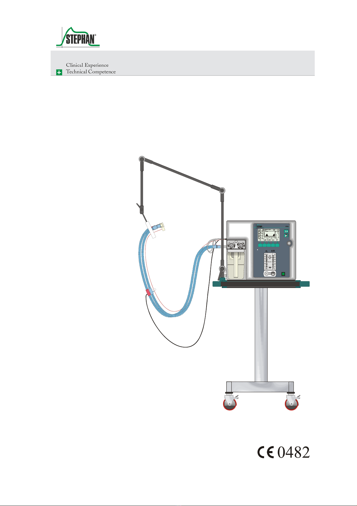
Alia
Ventilator
30
25
20
15
10
5
2
30
25
20
15
10
5
2
Med.
AIR
Alia
Steril es aqua dest.
max.
INSPI RATIONS- DRUCKEXPIRATIONS-DRUCK
mbar
PLATEAU
PEEP
40
1
20
15
50
5
60
10
30
0
AIR
O
2
Service Instructions

Preface
2 SA-112-0106V1.0-WEM-GB ©F. Stephan GmbH
These service instructions aim to provide assistance for troubleshooting
activities with the ALIA ventilator.
It contains drawings, circuit diagrams and parts lists for a better
understanding of how the ventilator works.
Service and maintenance work can be carried out to the peripheral
components of the ALIA ventilator. Repairs to the electronic control of
the ventilator can only be carried out by F. STEPHAN GMBH or authorized
service partners. Otherwise the entire electronic systems in the ALIA
ventilator require no maintenance.
Every step of a specific procedure should be read through carefully
before starting to service the unit. Always only use the correct tools and
the stated measuring equipment. Failure to follow the instructions and/or
recommendations in these service instructions can result in the device not
working properly or cause damage to the device.
Only use original spare parts by F. STEPHAN GMBH as contained in the
spare parts list (see chapter 10 p. 75).
These service instructions do not replace the operating instructions.
Handling the device in any way presumes an exact knowledge and
compliance with the operating instructions. The device is only intended
for the described purpose.
Service instructions
Note
F. Stephan GmbH
- Medizintechnik -
Kirchstrasse 19
56412 Gackenbach
Subject to technical alterations.
as of: Januar 2006
version: V1.0

®
Contents
©F. Stephan GmbH SA-112-0106V1.0-WEM-GB 3
Contents
Contents .....................................................................................................3
1General information...........................................................................5
1.1 Device name and manufacturer...............................................5
1.2 Maintenance and repairs..........................................................5
1.3 Abbreviations and definitions..................................................6
1.4 Safety instructions ...................................................................7
2Mechanical structure..........................................................................9
3Components and functions...............................................................15
3.1 Electronic controls.................................................................16
3.1.1 Sensor board..............................................................16
3.1.2 Controller board ........................................................20
3.1.3 Power Distribution Unit PDU ...................................22
3.2 Power supply .........................................................................25
3.2.1 Power supply unit......................................................26
3.2.2 Rechargeable battery.................................................27
3.2.3 Inverter......................................................................28
3.3 Gas supply .............................................................................29
3.3.1 Oxygen supply...........................................................30
3.3.2 Compressed air supply ..............................................31
3.4 Fresh gas reservoir.................................................................32
3.5 Patient part.............................................................................36
3.5.1 PEEP valve................................................................37
3.5.2 Plateau valve .............................................................38
3.5.3 Breathing gas humidifier...........................................38
3.6 Patient tube system................................................................40
3.6.1 Patient tube system for adults....................................40
3.6.2 Patient tube system for children................................42
3.6.3 Temperature sensor for patient tube system..............43
3.6.4 Pneumotachograph type D........................................44
3.6.5 Pneumotachograph Typ C.........................................44
4Serial interface.................................................................................45
4.1 Commands.............................................................................46

Contents
4 SA-112-0106V1.0-WEM-GB ©F. Stephan GmbH
4.2 Setting and querying the date and time..................................47
4.3 Output of measured values ....................................................48
5Tools and aids..................................................................................51
6Checks and maintenance..................................................................53
6.1 Every time before starting the device....................................53
6.2 Weekly...................................................................................54
6.3 ½ yearly.................................................................................55
6.3.1 ½ yearly maintenance basic unit ...............................55
6.3.2 Maintenance of the patient part.................................59
6.4 Safety checks.........................................................................60
6.4.1 Test report .................................................................61
7Troubleshooting...............................................................................69
8Annex...............................................................................................71
9List of illustrations...........................................................................73
10 List of tables.....................................................................................75
11 Place for your Notes.........................................................................77

®
1 General information
©F. Stephan GmbH SA-112-0106V1.0-WEM-GB 5
1 General information
1.1 Device name and manufacturer
ALIA
F. STEPHAN GMBH
- MEDIZINTECHNIK -
KIRCHSTRASSE 19
56412 GACKENBACH
(+)49 (6439) 9125 – 0
(+)49 (6439) 9125 – 111
www.stephan-gmbh.com
1.2 Maintenance and repairs
In the interests of device safety, maintenance of the ALIA ventilator
should be carried out every six months.
Safety checks must be carried out every six months.
Maintenance must be carried out by the authorized customer service of F.
STEPHAN GMBH.
Only spare parts from F. STEPHAN GMBH must be used during
maintenance.
Clean and disinfect the device respectively device parts every time before
maintenance, even when returning the device for repairs.
Device name
Manufacturer
Caution!

1 General information
6 SA-112-0106V1.0-WEM-GB ©F. Stephan GmbH
1.3 Abbreviations and definitions
Abbreviation Definition Meaning
%h Percentage hours Service life of the oxygen sensor in
hours depending on the oxygen
concentration
AIR Medical compressed air
aqua dest. Aqua destilata (lat.) Distilled, demineralized water
bar Unit of measurement for compressed
air
Batt Rechargeable battery Device for storing electrical energy in
the form of chemical energy
cmH2O Unit of measurement for compressed
air = mbar
FiO2Inspired oxygen concentration
IGR Incremental transducer Push button and knob
PDU Power distribution unit Power Distribution Unit
PEEP Positive end expiratory
pressure
V Volt Unit of measurement for electrical
voltage
Table 1: Abbreviations and definitions
®
1 General information
©F. Stephan GmbH SA-112-0106V1.0-WEM-GB 7
1.4 Safety instructions
Refers to instructions drawing attention to important facts.
The following safety instructions appear at relevant points in the service
instructions and must always be heeded.
Refers to warnings which, if not heeded, can result in malfunctions,
damage or defects in the device, which can possibly also put the patient at
danger.
Refers to precautions which, if not heeded, can result in damage to the
device and its accessories.
Warning
Caution

®
2 Mechanical structure
©F. Stephan GmbH SA-112-0106V1.0-WEM-GB 9
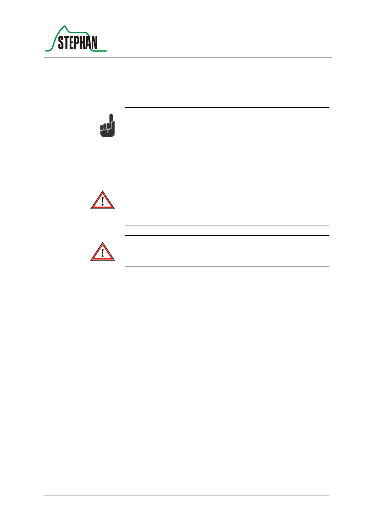
2 Mechanical structure
The ALIA ventilator consists of a basic housing and a front housing. The
front housing also acts as the device cover.
Fig. 1: Basic and front housing: general
Remove the front housing to open the ALIA ventilator.
Risk of an electric shock
Disconnect from the power source before opening the housing!
The front housing is screwed to the frame with 15 countersunk screws
M4x10. The 9 screws used on the side of the device are also fitted with
rosettes to prevent damage to the plastic front housing when tightening
the screws.
Fig. 1: Opening the housing
The front housing can now be hinged open to the front.
Front housing
Warning
2 Mechanical structure
10 SA-112-0106V1.0-WEM-GB ©F. Stephan GmbH
Fig. 2: Hinging open the housing
Before hinging open the front housing, ensure that the connectors for the
tube heating, the temperature sensors and the pneumotachograph have
been disconnected.
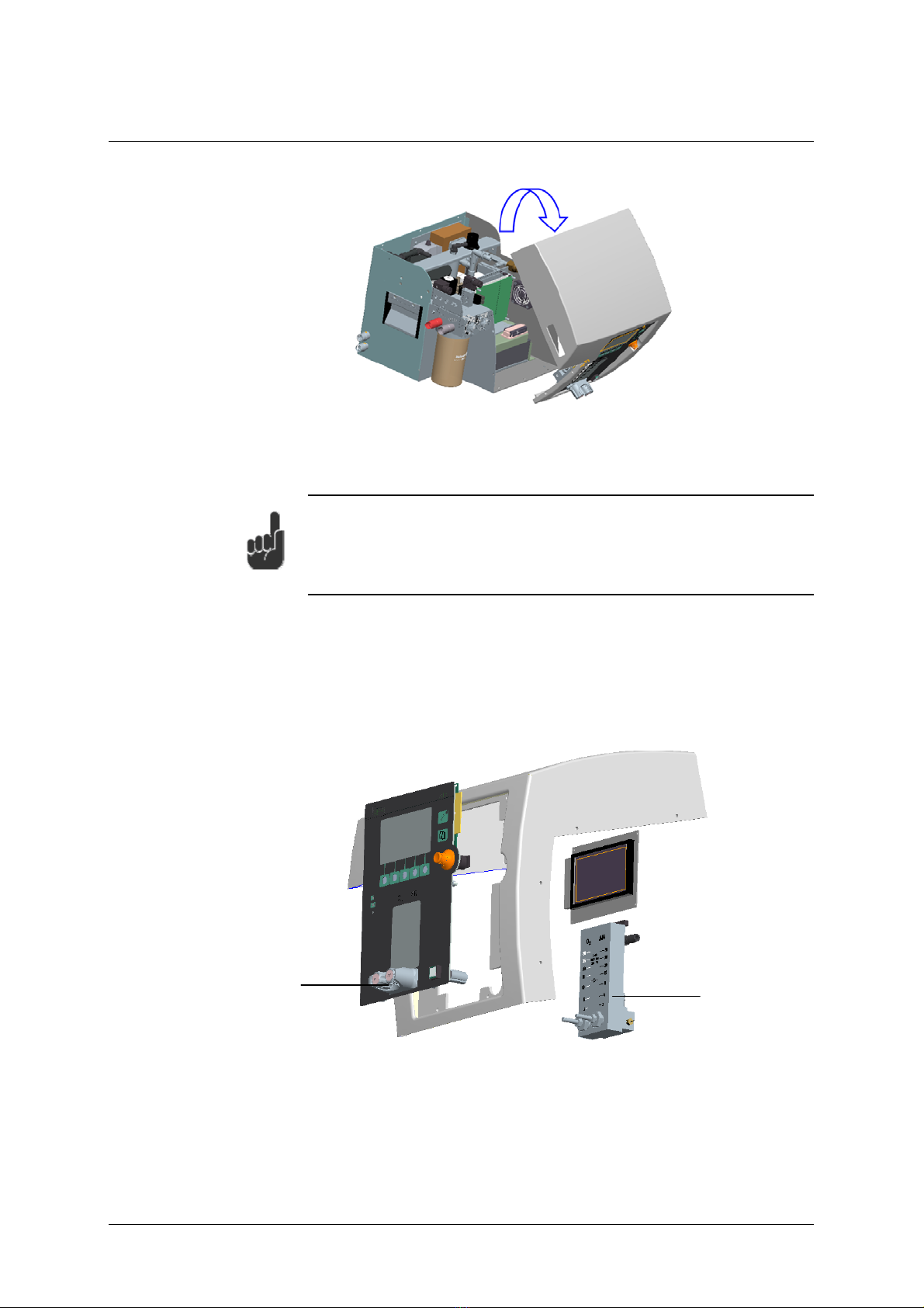
The plastic front housing is coated with an EMC varnish on the inside. It
contains the input periphery of the ALIA ventilator.
This input periphery consists of touch buttons, the IGR (push/turn knob),
the LCD display, the controller board, the double flowmeter ON/OFF
switch on the front pane.
Fig. 3: Front housing with input periphery
1 double flow meter
2 FiO2and flow adjustment
1
2
®
2 Mechanical structure
©F. Stephan GmbH SA-112-0106V1.0-WEM-GB 11
The frame of the ALIA ventilator and its reinforcement bar, fastening
bracket and panels consist of 2 mm thick powder-coated aluminium. The
bottom of the housing has a cut-out for the rechargeable battery.
Fig. 4: Basic housing
1 Reinforcement bar
2 Cut-out for rechargeable battery
3 Rechargeable battery
The intake filter and oxygen sensor are located behind a service flap on
the back of the ventilator.
To open the service flap, loosen the knurled screws by turning counter-
clockwise.
The oxygen sensor is located on the left next to the intake filter. It is
screwed into the connection block.
It can be removed by turning counter-clockwise.
The electrical connection between the oxygen sensor and device consists
of a 2-pin AMP connector.
Basic housing
Service flap
2
3
1

2 Mechanical structure
12 SA-112-0106V1.0-WEM-GB ©F. Stephan GmbH
Fig. 5: Service flap
1 Intake filter 3 Oxygen sensor
2 Service flap
On the left and right side wall there are recessed handles for carrying the
ALIA ventilator.
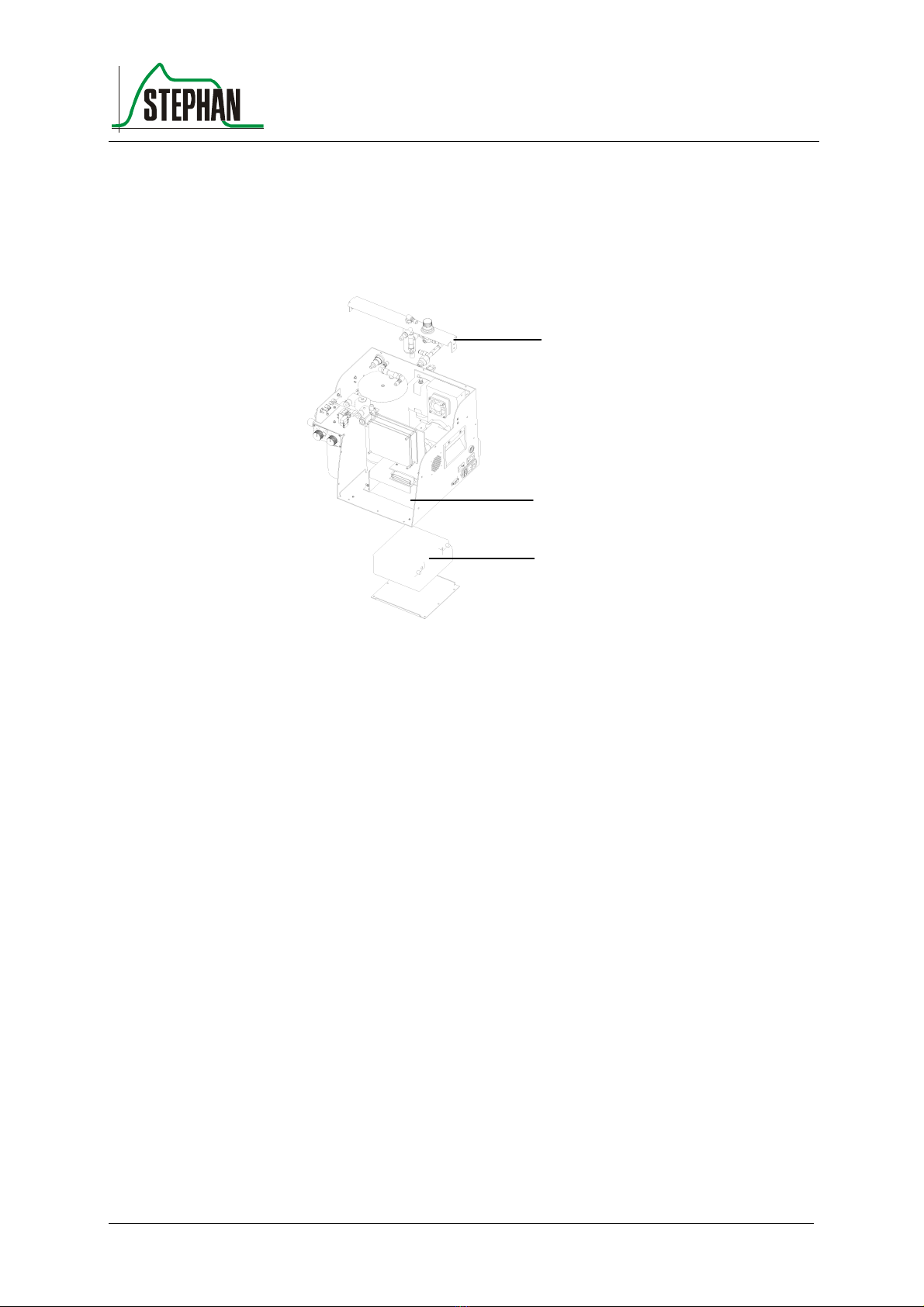
Some of the electronic controls and the power supply are accommodated
inside the ventilator.
Fig. 6: Electronic components
1 Power supply 3 Electronic controls
2 Cold device connector combination
2
1
3
1
2
3

®
2 Mechanical structure
©F. Stephan GmbH SA-112-0106V1.0-WEM-GB 13
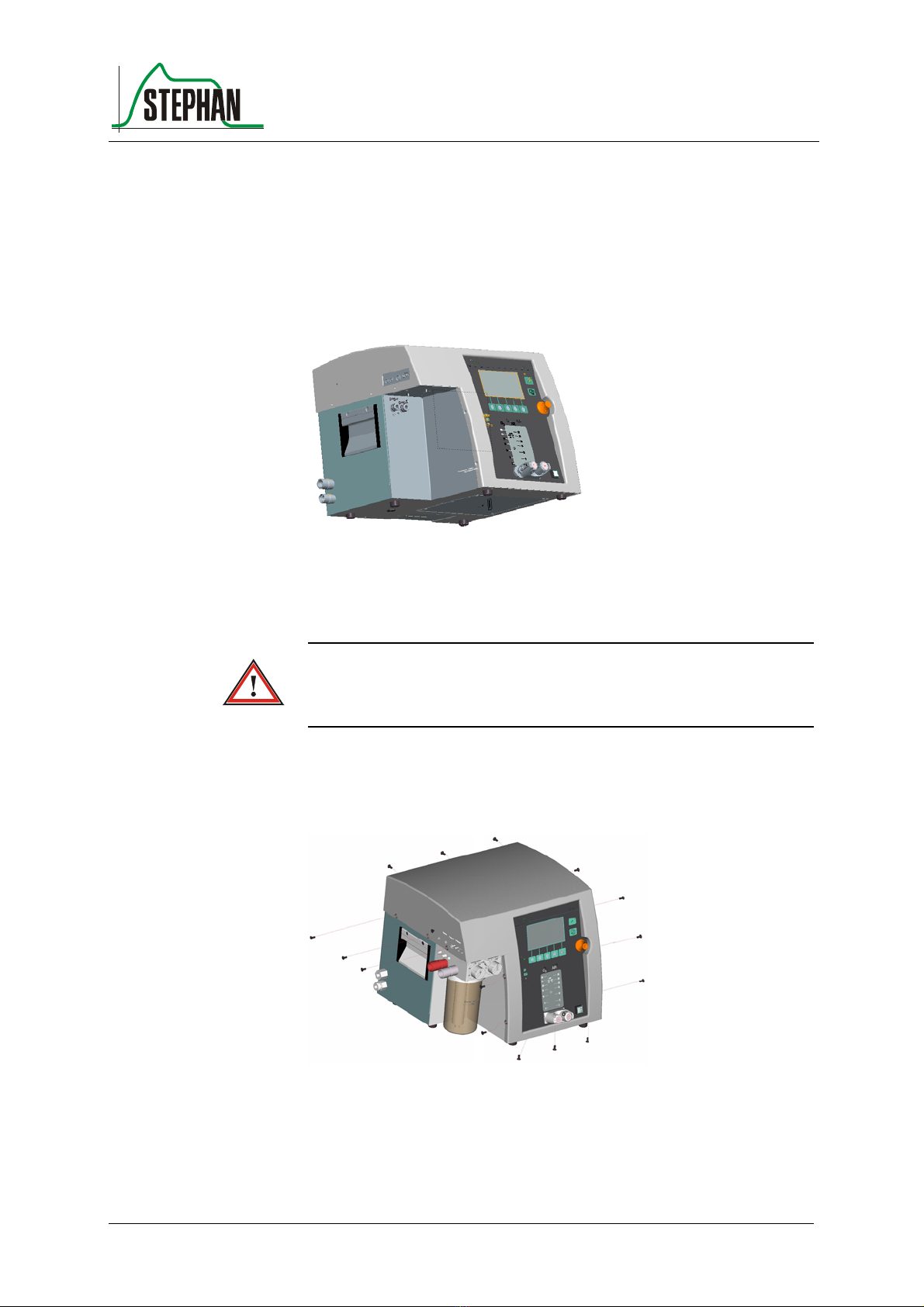
The entire pneumatic system is accommodated in the basic housing. Only
the double flowmeter is in the front housing.
The pneumatic system consists of the compressor, the fresh gas reservoir
and its control valves. The pressure switches for detecting the intake
pressure are firmly integrated in the pneumatic system
Fig. 7: pneumatic components
1 compressor 2 fresh gas reservoir
3 gas inlets 4 service flap
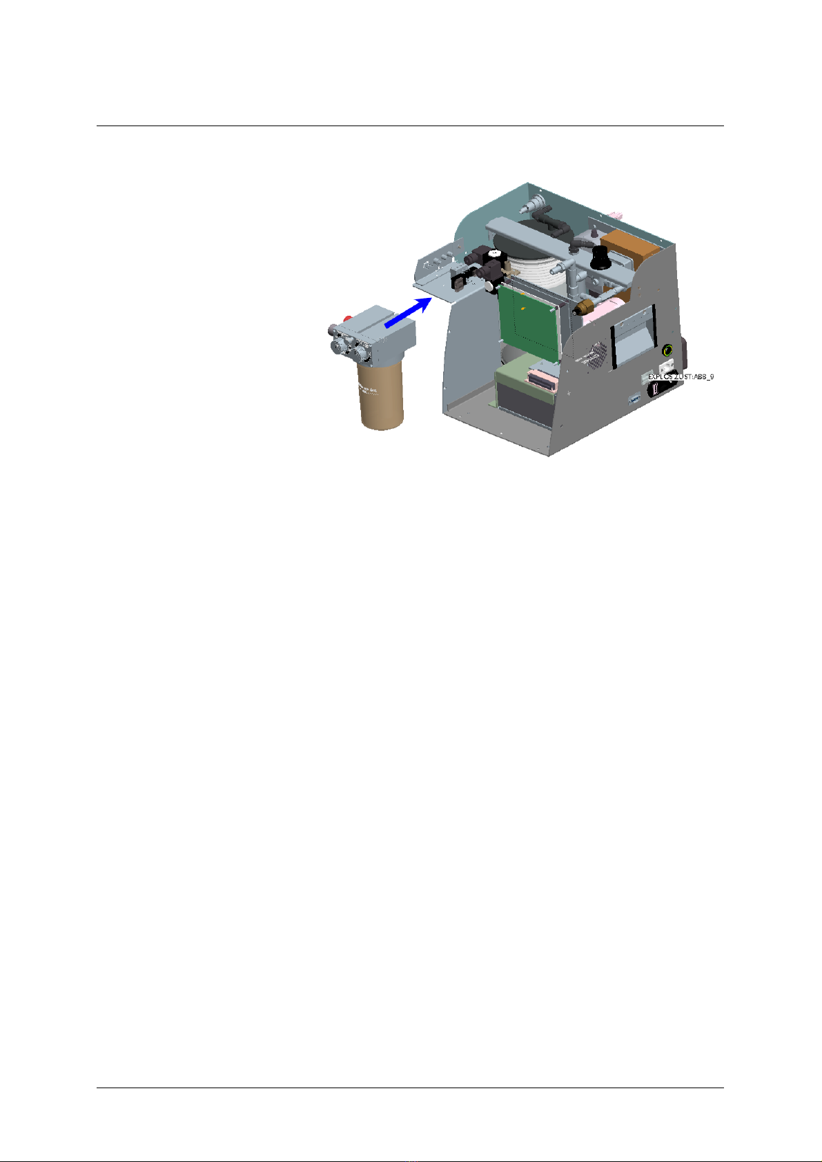
The patient part is connected to the basic device from the front.
The patient part is held in position by the guide rail.
2
3
4
1
2 Mechanical structure
14 SA-112-0106V1.0-WEM-GB ©F. Stephan GmbH
Fig. 8: Inserting the patient part


3 Components and functions
16 SA-112-0106V1.0-WEM-GB ©F. Stephan GmbH
3.1 Electronic controls
The ALIA ventilator uses an 8-bit micro controller. This controls the
sensors and actuators in the system.
In addition to these components, the unit also has electronic components
which provide the electrical power supply.
These consist of a power supply unit and a device for bridging any power
failure. In the event of a power failure, the device switches over to battery
operation and regulates the battery charging process.
The sensor board generates voltages of ±15V and -5V, and the controller
board generates + 5V.
3.1.1 Sensor board
The sensor board acts as interface for triggering the actuators (control of
the fresh gas reservoir and the expiration valve) and for registering the
measured data (pressure and differential pressure sensors, AD converter).
An SPI bus system provides the link to the micro controller. This
simplifies linking the various components in terms of both hardware and
software.
The following illustration shows the components on the sensor board.
Abb. 2: Sensor board

®
3 Components and functions
©F. Stephan GmbH SA-112-0106V1.0-WEM-GB 17
The main task of the sensor board is to convert the analog signals.
Rechargeable battery voltage
"DC_good"signal
On/off signal
Input voltage
12 V (for heating and valves)
Inspired pressure
Expired pressure
Flow sensor differential pressure
Oxygen sensor cell voltage
Heating
Valves
"Batt_enable"
The power supply for the electronic components is generated by a
DC/DC converter on the sensor board, generating +15V, -5V and -15V.
The input signals for On/Off, DC_good, input voltage and "Batt_enable"
are sent to the SPI bus by a slide register. The input signals for pressure,
flow, O2and battery voltage are sent to the SPI bus following
amplification and conversion via an 8-channel AD/12 bit converter.
The AD converter is equipped with protective diodes (max. 5V) on the
input side.
A serial chargeable slide register with power amplifier is used for
triggering the heating and the valves, via the SPI bus.
The respiratory pressure is measured at the inspiration fitting of the
patient part. The pressure present here is conveyed via a tube to the
pressure sensors (respiratory pressure).
For safety reasons, two pressure sensors are provided for measuring the
respiratory pressure.
The differential pressure developing over the resistance body of the PNT
head is used for measurement of the volume flow. This differential
pressure is conveyed via two tubes to the differential pressure sensor.
Main tas
k
Voltage signals (input):
Voltage signals
(output):
Pressure sensors

3 Components and functions
18 SA-112-0106V1.0-WEM-GB ©F. Stephan GmbH
Fig. 10: PNT and pressure fitting
1 hose heating socket
2 temperature sensor socket
4 electrical connection magnetic
coil
3 pneumotachograph connector 5 pressure fittings
6 water bath connectors
The calibration block allows for offset calibration of the differential
pressure sensor and the oxygen sensor.
The interposed solenoids V4 and V5 switch the measuring lines of the
differential pressure sensor against the atmosphere. The valves are
switched at exactly the same time. The value measured in this way
corresponds to a flow of 0 l/min.
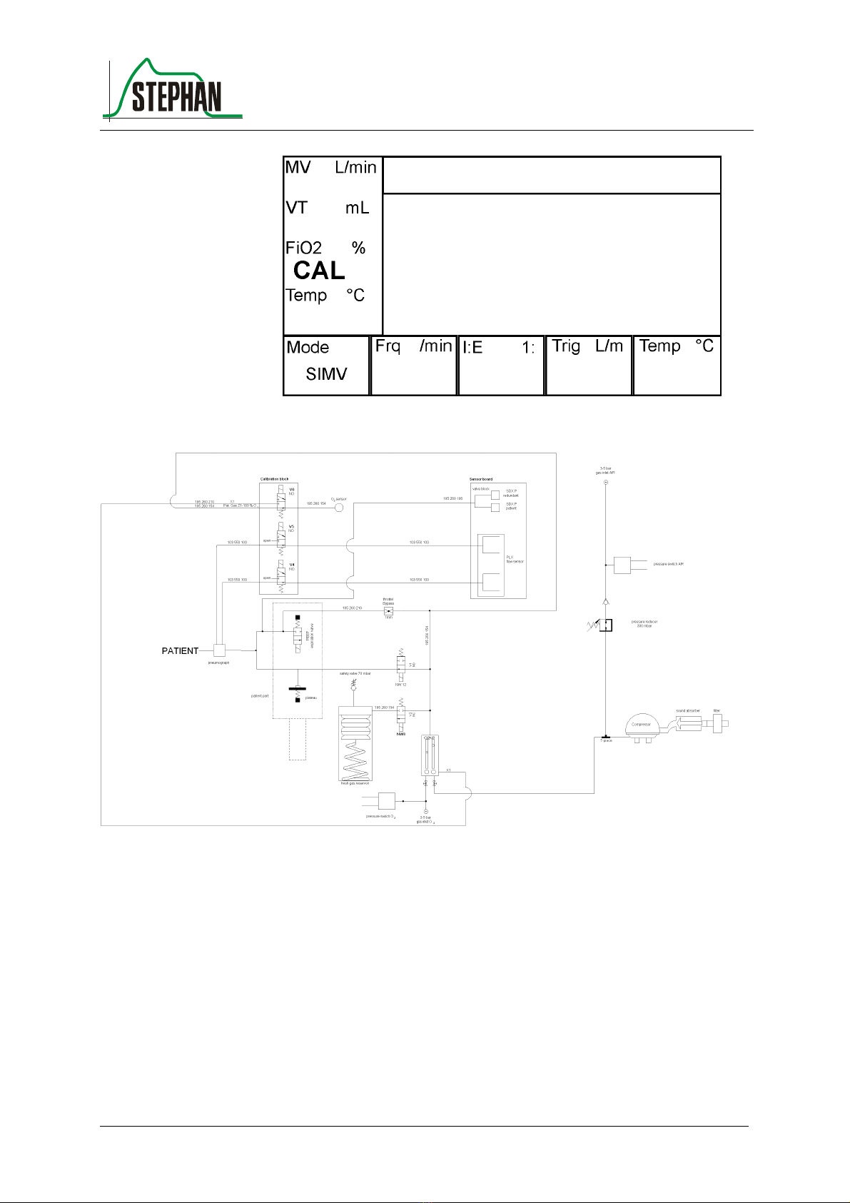
FiO2measurement is carried out using an electrochemical cell (fuel cell).
This oxygen sensor generates a voltage depending on the prevailing
oxygen concentration. The voltage is then converted electronically into a
corresponding signal.
To calibrate the oxygen sensor, compressed air ( 21% O2) is blown
against it via solenoid V6. During this procedure, the display shows
"CAL" in the window of the FiO2value. After completing calibration, the
valve switches the oxygen sensor back to the output of the double
flowmeter.
Calibration bloc
k
FiO2 measurement
3
6
2
4
5
1
®
3 Components and functions
©F. Stephan GmbH SA-112-0106V1.0-WEM-GB 19
Fig. 11: Display showing 'CAL'
Fig. 12: Pneumatic function diagram

3 Components and functions
20 SA-112-0106V1.0-WEM-GB ©F. Stephan GmbH
3.1.2 Controller board
Fig. 13: Controller board
1 PDU board 2 controller board
Various functional groups are accommodated on the controller board.
The figure shows the functional groups for the user interface, CPU and
interfaces.
The user interface consists of the keyboard, display (LCD) and LEDs as
input and output units for regular handling of the system. The controller
board also contains the alarm system for indicating alarm statuses.
The digital interfaces for triggering the actuators and reading the sensors
(via the sensor board) are integrated on the controller board.
1
2
Table of contents
Other Stephan Medical Equipment manuals


Popular Medical Equipment manuals by other brands


Getinge
Getinge Arjohuntleigh Nimbus 3 Professional Instructions for use

Mettler Electronics
Mettler Electronics Sonicator 730 Maintenance manual

Pressalit Care
Pressalit Care R1100 Mounting instruction

Denas MS
Denas MS DENAS-T operating manual

bort medical
bort medical ActiveColor quick guide

AccuVein
AccuVein AV400 user manual


